User Guide - Eurotherm Ltda
User Guide - Eurotherm Ltda
User Guide - Eurotherm Ltda

Create successful ePaper yourself
Turn your PDF publications into a flip-book with our unique Google optimized e-Paper software.
nanodac<strong>User</strong> <strong>Guide</strong>nanodac recorder/controllerVersions 5.00 and laterHA030554/7November 2012
© 2012 <strong>Eurotherm</strong> LimitedAll rights are strictly reserved. No part of this document may be reproduced, modified, or transmittedin any form by any means, nor may it be stored in a retrieval system other than for the purposeto act as an aid in operating the equipment to which the document relates, without the prior, writtenpermission of <strong>Eurotherm</strong> Limited.<strong>Eurotherm</strong> Limited pursues a policy of continuous development and product improvement. Thespecification in this document may therefore be changed without notice. The information in thisdocument is given in good faith, but is intended for guidance only. <strong>Eurotherm</strong> Limited will acceptno responsibility for any losses arising from errors in this document.
Declaration of ConformityManufacturer's name:Manufacturer's address:Product type:Models:<strong>Eurotherm</strong> LimitedFaraday Close, Worthing, West Sussex,BN13 3PL, United KingdomRecorder / controllernanodac Status level A1 and aboveSafety specification: EN61010-1: 2001EMC emissions specification: EN61326-1: 2006 Class B (100 to 230V ac supply)EN61326-1: 2006 Class A (24V ac/dc supply)EMC immunity specification:EN61326-1: 2006 Industrial locations<strong>Eurotherm</strong> Limited hereby declares that the above products conform to the safety andEMC specifications listed. <strong>Eurotherm</strong> Limited further declares that the above productscomply with the EMC Directive 2004/108/EC, and also with the Low Voltage Directive2006/95/EC.Signed:Dated:Signed for and on behalf of <strong>Eurotherm</strong> Limited.Kevin Shaw(R&D Director)IA249986U790 Issue 2 Oct 10 (CN26774)
nanodac RECORDER/CONTROLLER: USER GUIDEnanodac Recorder/Controller<strong>User</strong> <strong>Guide</strong>List of sectionsSectionPage1 Introduction . . . . . . . . . . . . . . . . . . . . . . . . . . . . . . . . . . . . . . . . . . . . . . . . . . . . . 32 Installation. . . . . . . . . . . . . . . . . . . . . . . . . . . . . . . . . . . . . . . . . . . . . . . . . . . . . . . 33 Operation . . . . . . . . . . . . . . . . . . . . . . . . . . . . . . . . . . . . . . . . . . . . . . . . . . . . . . . 84 Configuration . . . . . . . . . . . . . . . . . . . . . . . . . . . . . . . . . . . . . . . . . . . . . . . . . . . . 565 Modbus TCP slave comms . . . . . . . . . . . . . . . . . . . . . . . . . . . . . . . . . . . . . . . . . 1706 iTools . . . . . . . . . . . . . . . . . . . . . . . . . . . . . . . . . . . . . . . . . . . . . . . . . . . . . . . . . . . 2577 <strong>User</strong> Wiring . . . . . . . . . . . . . . . . . . . . . . . . . . . . . . . . . . . . . . . . . . . . . . . . . . . . . . 2878 USB Devices . . . . . . . . . . . . . . . . . . . . . . . . . . . . . . . . . . . . . . . . . . . . . . . . . . . . . 292A Technical specification . . . . . . . . . . . . . . . . . . . . . . . . . . . . . . . . . . . . . . . . . . . . 293B Control Loops . . . . . . . . . . . . . . . . . . . . . . . . . . . . . . . . . . . . . . . . . . . . . . . . . . . 299C Reference . . . . . . . . . . . . . . . . . . . . . . . . . . . . . . . . . . . . . . . . . . . . . . . . . . . . . . . 327D Configuration menu overview . . . . . . . . . . . . . . . . . . . . . . . . . . . . . . . . . . . . . 335E Web Server. . . . . . . . . . . . . . . . . . . . . . . . . . . . . . . . . . . . . . . . . . . . . . . . . . . . . . 351F Labview Driver. . . . . . . . . . . . . . . . . . . . . . . . . . . . . . . . . . . . . . . . . . . . . . . . . . . 361Index . . . . . . . . . . . . . . . . . . . . . . . . . . . . . . . . . . . . . . . . . . . . . . . . . . . . . . . . . . . . . 367Associated documentsHA028838 Printable version of iTools HelpHA025464 EMC installation guidelinesHA027962 Printable version of ‘Review’ HelpApplication notesHA030817U001 Archiving data from the nanodac recorder/controllerHA030817U002 Heat/Cool with carbon potential or oxygen level monitoringHA030817U003 Heat only temperature control and carbon potential controlHA030817U004 Virtual channels using the nanodac recorder/controller.Software effectivityThis manual refers to instruments fitted with software version 5.0.Software versions 2.20 onwards are ‘backwards compatible’ so that it can be used onall hardware versions of the unit.Previous software versions are not compatible with instruments with hardware statusgreater than 2.The status level may be found on the instrument label and consists of a letter indicatingsoftware status followed by a numeral indicating the hardware status (e.g. ‘B2’)HA030554Issue 7 Nov 12Page i
nanodac RECORDER/CONTROLLER: USER GUIDEnanodac Recorder/Controller<strong>User</strong> <strong>Guide</strong>Contents ListSection1 INTRODUCTION . . . . . . . . . . . . . . . . . . . . . . . . . . . . . . . . . . . . . . . . . . 31.1 UNPACKING THE INSTRUMENT . . . . . . . . . . . . . . . . . . . . . . . . . . . . . . . . . . . . . 32 INSTALLATION . . . . . . . . . . . . . . . . . . . . . . . . . . . . . . . . . . . . . . . . . . . . 32.1 MECHANICAL INSTALLATION . . . . . . . . . . . . . . . . . . . . . . . . . . . . . . . . . . . . . . . 32.1.1 Installation Procedure . . . . . . . . . . . . . . . . . . . . . . . . . . . . . . . . . . . . . . . . . . 32.1.2 Demounting . . . . . . . . . . . . . . . . . . . . . . . . . . . . . . . . . . . . . . . . . . . . . . . . . . 32.2 ELECTRICAL INSTALLATION . . . . . . . . . . . . . . . . . . . . . . . . . . . . . . . . . . . . . . . . 52.2.1 Termination details . . . . . . . . . . . . . . . . . . . . . . . . . . . . . . . . . . . . . . . . . . . . 52.2.2 Low Voltage Option . . . . . . . . . . . . . . . . . . . . . . . . . . . . . . . . . . . . . . . . . . . 72.2.3 Dual Input Option . . . . . . . . . . . . . . . . . . . . . . . . . . . . . . . . . . . . . . . . . . . . 72.2.4 Modbus Master communications . . . . . . . . . . . . . . . . . . . . . . . . . . . . . . . . 72.2.5 EtherNet/IP . . . . . . . . . . . . . . . . . . . . . . . . . . . . . . . . . . . . . . . . . . . . . . . . . . . 73 OPERATION . . . . . . . . . . . . . . . . . . . . . . . . . . . . . . . . . . . . . . . . . . . . . 83.1 INTRODUCTION . . . . . . . . . . . . . . . . . . . . . . . . . . . . . . . . . . . . . . . . . . . . . . . . . . . 83.1.1 Display Screen . . . . . . . . . . . . . . . . . . . . . . . . . . . . . . . . . . . . . . . . . . . . . . . . 83.1.2 Navigation Pushbuttons . . . . . . . . . . . . . . . . . . . . . . . . . . . . . . . . . . . . . . . . 83.1.3 On Screen Help . . . . . . . . . . . . . . . . . . . . . . . . . . . . . . . . . . . . . . . . . . . . . . . 93.2 PROCESS VARIABLE DISPLAY . . . . . . . . . . . . . . . . . . . . . . . . . . . . . . . . . . . . . . . 103.2.1 Alarm Icons . . . . . . . . . . . . . . . . . . . . . . . . . . . . . . . . . . . . . . . . . . . . . . . . . . 103.2.2 Status Bar Icons . . . . . . . . . . . . . . . . . . . . . . . . . . . . . . . . . . . . . . . . . . . . . . . 113.2.3 Breaks in recording . . . . . . . . . . . . . . . . . . . . . . . . . . . . . . . . . . . . . . . . . . . . 133.3 TOP LEVEL MENU . . . . . . . . . . . . . . . . . . . . . . . . . . . . . . . . . . . . . . . . . . . . . . . . . . 143.3.1 Home . . . . . . . . . . . . . . . . . . . . . . . . . . . . . . . . . . . . . . . . . . . . . . . . . . . . . . . . 143.3.2 Configuration . . . . . . . . . . . . . . . . . . . . . . . . . . . . . . . . . . . . . . . . . . . . . . . . . 143.3.3 Go to View . . . . . . . . . . . . . . . . . . . . . . . . . . . . . . . . . . . . . . . . . . . . . . . . . . . . 153.3.4 History . . . . . . . . . . . . . . . . . . . . . . . . . . . . . . . . . . . . . . . . . . . . . . . . . . . . . . . 183.3.5 Faceplate Cycling on/off . . . . . . . . . . . . . . . . . . . . . . . . . . . . . . . . . . . . . . . . 183.3.6 Operator Notes . . . . . . . . . . . . . . . . . . . . . . . . . . . . . . . . . . . . . . . . . . . . . . . 183.3.7 Demand Archiving . . . . . . . . . . . . . . . . . . . . . . . . . . . . . . . . . . . . . . . . . . . . . 183.3.8 Login . . . . . . . . . . . . . . . . . . . . . . . . . . . . . . . . . . . . . . . . . . . . . . . . . . . . . . . . 203.4 DISPLAY MODES . . . . . . . . . . . . . . . . . . . . . . . . . . . . . . . . . . . . . . . . . . . . . . . . . . 223.4.1 Vertical Trend . . . . . . . . . . . . . . . . . . . . . . . . . . . . . . . . . . . . . . . . . . . . . . . . . 223.4.2 Horizontal Trend mode . . . . . . . . . . . . . . . . . . . . . . . . . . . . . . . . . . . . . . . . . 233.4.3 Vertical Bargraph mode . . . . . . . . . . . . . . . . . . . . . . . . . . . . . . . . . . . . . . . . 233.4.4 Horizontal Bargraph mode . . . . . . . . . . . . . . . . . . . . . . . . . . . . . . . . . . . . . . 243.4.5 Numeric mode . . . . . . . . . . . . . . . . . . . . . . . . . . . . . . . . . . . . . . . . . . . . . . . . 243.4.6 Alarm panel . . . . . . . . . . . . . . . . . . . . . . . . . . . . . . . . . . . . . . . . . . . . . . . . . . . 253.4.7 Control Loop1/Loop2 . . . . . . . . . . . . . . . . . . . . . . . . . . . . . . . . . . . . . . . . . . 263.4.8 Cascade Display Mode . . . . . . . . . . . . . . . . . . . . . . . . . . . . . . . . . . . . . . . . . 273.4.9 Programmer Display Mode . . . . . . . . . . . . . . . . . . . . . . . . . . . . . . . . . . . . . 283.4.10 Steriliser display mode . . . . . . . . . . . . . . . . . . . . . . . . . . . . . . . . . . . . . . . . 403.4.11 Promote list . . . . . . . . . . . . . . . . . . . . . . . . . . . . . . . . . . . . . . . . . . . . . . . . . . 443.4.12 Modbus Master display mode . . . . . . . . . . . . . . . . . . . . . . . . . . . . . . . . . . 453.4.13 EtherNet/IP display mode . . . . . . . . . . . . . . . . . . . . . . . . . . . . . . . . . . . . . 473.5 TREND HISTORY . . . . . . . . . . . . . . . . . . . . . . . . . . . . . . . . . . . . . . . . . . . . . . . . . . . 533.5.1 Navigation . . . . . . . . . . . . . . . . . . . . . . . . . . . . . . . . . . . . . . . . . . . . . . . . . . . . 533.5.2 History Options Menu . . . . . . . . . . . . . . . . . . . . . . . . . . . . . . . . . . . . . . . . . . 543.6 TEXT ENTRY . . . . . . . . . . . . . . . . . . . . . . . . . . . . . . . . . . . . . . . . . . . . . . . . . . . . . . . 553.6.1 Numeric keyboard . . . . . . . . . . . . . . . . . . . . . . . . . . . . . . . . . . . . . . . . . . . . . 553.6.2 USB keyboard . . . . . . . . . . . . . . . . . . . . . . . . . . . . . . . . . . . . . . . . . . . . . . . . . 554 CONFIGURATION . . . . . . . . . . . . . . . . . . . . . . . . . . . . . . . . . . . . . . . . .564.1 INSTRUMENT MENU . . . . . . . . . . . . . . . . . . . . . . . . . . . . . . . . . . . . . . . . . . . . . . . 574.1.1 Clock . . . . . . . . . . . . . . . . . . . . . . . . . . . . . . . . . . . . . . . . . . . . . . . . . . . . . . . . 58Page iiHA030554Issue 7 Nov 12
nanodac RECORDER/CONTROLLER: USER GUIDEList of Contents (Cont.)SectionPage4.1.2 Locale . . . . . . . . . . . . . . . . . . . . . . . . . . . . . . . . . . . . . . . . . . . . . . . . . . . . . . . . 594.1.3 Display configuration . . . . . . . . . . . . . . . . . . . . . . . . . . . . . . . . . . . . . . . . . . 604.1.4 Info menu . . . . . . . . . . . . . . . . . . . . . . . . . . . . . . . . . . . . . . . . . . . . . . . . . . . . 624.1.5 Upgrade . . . . . . . . . . . . . . . . . . . . . . . . . . . . . . . . . . . . . . . . . . . . . . . . . . . . . 634.1.6 Security menu . . . . . . . . . . . . . . . . . . . . . . . . . . . . . . . . . . . . . . . . . . . . . . . . . 644.1.7 I/O fitted . . . . . . . . . . . . . . . . . . . . . . . . . . . . . . . . . . . . . . . . . . . . . . . . . . . . . 664.1.8 Save/Restore . . . . . . . . . . . . . . . . . . . . . . . . . . . . . . . . . . . . . . . . . . . . . . . . . . 674.1.9 Input adjust . . . . . . . . . . . . . . . . . . . . . . . . . . . . . . . . . . . . . . . . . . . . . . . . . . . 684.1.10 Output adjust . . . . . . . . . . . . . . . . . . . . . . . . . . . . . . . . . . . . . . . . . . . . . . . . 714.2 NETWORK MENU . . . . . . . . . . . . . . . . . . . . . . . . . . . . . . . . . . . . . . . . . . . . . . . . . . 724.2.1 Interface . . . . . . . . . . . . . . . . . . . . . . . . . . . . . . . . . . . . . . . . . . . . . . . . . . . . . . 724.2.2 Archiving . . . . . . . . . . . . . . . . . . . . . . . . . . . . . . . . . . . . . . . . . . . . . . . . . . . . . 734.2.3 FTP Server . . . . . . . . . . . . . . . . . . . . . . . . . . . . . . . . . . . . . . . . . . . . . . . . . . . . 754.2.4 Modbus TCP . . . . . . . . . . . . . . . . . . . . . . . . . . . . . . . . . . . . . . . . . . . . . . . . . . 764.3 GROUP CONFIGURATION . . . . . . . . . . . . . . . . . . . . . . . . . . . . . . . . . . . . . . . . . . 774.3.1 Group Trend configuration . . . . . . . . . . . . . . . . . . . . . . . . . . . . . . . . . . . . . 774.3.2 Group Recording configuration . . . . . . . . . . . . . . . . . . . . . . . . . . . . . . . . . 784.4 INPUT CHANNEL CONFIGURATION . . . . . . . . . . . . . . . . . . . . . . . . . . . . . . . . . 794.4.1 Channel Main . . . . . . . . . . . . . . . . . . . . . . . . . . . . . . . . . . . . . . . . . . . . . . . . . 804.4.2 Channel Trend configuration . . . . . . . . . . . . . . . . . . . . . . . . . . . . . . . . . . . . 844.4.3 Alarm 1 menu . . . . . . . . . . . . . . . . . . . . . . . . . . . . . . . . . . . . . . . . . . . . . . . . . 854.4.4 Alarm 2 menu . . . . . . . . . . . . . . . . . . . . . . . . . . . . . . . . . . . . . . . . . . . . . . . . . 864.4.5 Alarm types . . . . . . . . . . . . . . . . . . . . . . . . . . . . . . . . . . . . . . . . . . . . . . . . . . . 874.5 VIRTUAL CHANNEL CONFIGURATION . . . . . . . . . . . . . . . . . . . . . . . . . . . . . . . 894.5.1 Maths channel configuration . . . . . . . . . . . . . . . . . . . . . . . . . . . . . . . . . . . . 894.5.2 Totaliser configuration . . . . . . . . . . . . . . . . . . . . . . . . . . . . . . . . . . . . . . . . . 914.5.3 Wiring Example using a counter in combination with a totaliser . . . . . 954.5.4 Counter configuration . . . . . . . . . . . . . . . . . . . . . . . . . . . . . . . . . . . . . . . . . . 964.6 LOOP OPTION CONFIGURATION . . . . . . . . . . . . . . . . . . . . . . . . . . . . . . . . . . . 984.6.1 Main menu parameters . . . . . . . . . . . . . . . . . . . . . . . . . . . . . . . . . . . . . . . . . 994.6.2 Setup menu parameters . . . . . . . . . . . . . . . . . . . . . . . . . . . . . . . . . . . . . . . . 994.6.3 Tune menu parameters . . . . . . . . . . . . . . . . . . . . . . . . . . . . . . . . . . . . . . . . . 1004.6.4 PID menu parameters . . . . . . . . . . . . . . . . . . . . . . . . . . . . . . . . . . . . . . . . . . 1014.6.5 Setpoint menu parameters . . . . . . . . . . . . . . . . . . . . . . . . . . . . . . . . . . . . . . 1024.6.6 Output menu items . . . . . . . . . . . . . . . . . . . . . . . . . . . . . . . . . . . . . . . . . . . . 1034.6.7 Loop diagnostics . . . . . . . . . . . . . . . . . . . . . . . . . . . . . . . . . . . . . . . . . . . . . . 1054.7 ADVANCED LOOP CONFIGURATION . . . . . . . . . . . . . . . . . . . . . . . . . . . . . . . . 1064.7.1 Advanced Loop Main menu . . . . . . . . . . . . . . . . . . . . . . . . . . . . . . . . . . . . . 1074.7.2 Advanced Loop Setup menu . . . . . . . . . . . . . . . . . . . . . . . . . . . . . . . . . . . . 1084.7.3 Advanced Loop Tune menu . . . . . . . . . . . . . . . . . . . . . . . . . . . . . . . . . . . . . 1094.7.4 Advanced Loop Master PID menu . . . . . . . . . . . . . . . . . . . . . . . . . . . . . . . 1134.7.5 Advanced Loop Slave PID menu . . . . . . . . . . . . . . . . . . . . . . . . . . . . . . . . . 1144.7.6 Advanced Loop Master SP menu . . . . . . . . . . . . . . . . . . . . . . . . . . . . . . . . 1164.7.7 Advanced Loop Slave SP menu . . . . . . . . . . . . . . . . . . . . . . . . . . . . . . . . . . 1184.7.8 Advanced Loop Output menu . . . . . . . . . . . . . . . . . . . . . . . . . . . . . . . . . . . 1204.7.9 Advanced Loop Diagnostics menu . . . . . . . . . . . . . . . . . . . . . . . . . . . . . . . 1234.8 PROGRAMMER CONFIGURATION . . . . . . . . . . . . . . . . . . . . . . . . . . . . . . . . . . . 1244.8.1 Programmer Features menu . . . . . . . . . . . . . . . . . . . . . . . . . . . . . . . . . . . . 1254.8.2 Programmer FTP menu . . . . . . . . . . . . . . . . . . . . . . . . . . . . . . . . . . . . . . . . . 1274.8.3 Programmer Setup menu . . . . . . . . . . . . . . . . . . . . . . . . . . . . . . . . . . . . . . . 1284.8.4 Programmer Run menu . . . . . . . . . . . . . . . . . . . . . . . . . . . . . . . . . . . . . . . . . 1314.8.5 Connecting the programmer to a loop . . . . . . . . . . . . . . . . . . . . . . . . . . 1334.8.6 Configuration by Modbus Comms . . . . . . . . . . . . . . . . . . . . . . . . . . . . . . . 1354.9 MODBUS MASTER CONFIGURATION . . . . . . . . . . . . . . . . . . . . . . . . . . . . . . . . 1364.9.1 Slave Main menu . . . . . . . . . . . . . . . . . . . . . . . . . . . . . . . . . . . . . . . . . . . . . . 1374.9.2 Slave Diagnostics menu . . . . . . . . . . . . . . . . . . . . . . . . . . . . . . . . . . . . . . . . 1384.9.3 Modbus master data configuration . . . . . . . . . . . . . . . . . . . . . . . . . . . . . . . 1394.10 ETHERNET/IP CONFIGURATION . . . . . . . . . . . . . . . . . . . . . . . . . . . . . . . . . . . 1424.10.1 Ethernet/IP Configuration Main menu . . . . . . . . . . . . . . . . . . . . . . . . . . . 1424.10.2 Implicit inputs/outputs . . . . . . . . . . . . . . . . . . . . . . . . . . . . . . . . . . . . . . . . 1434.10.3 Explicit inputs/outputs . . . . . . . . . . . . . . . . . . . . . . . . . . . . . . . . . . . . . . . . 1434.11 WEB SERVER . . . . . . . . . . . . . . . . . . . . . . . . . . . . . . . . . . . . . . . . . . . . . . . . . . . . . 1454.11.1 Configuration Display . . . . . . . . . . . . . . . . . . . . . . . . . . . . . . . . . . . . . . . . . 145HA030554Issue 7 Nov 12Page iii
nanodac RECORDER/CONTROLLER: USER GUIDEList of Contents (Cont.)SectionPage4.12 DIGITAL I/O . . . . . . . . . . . . . . . . . . . . . . . . . . . . . . . . . . . . . . . . . . . . . . . . . . . . . . 1464.12.1 Digital input/output . . . . . . . . . . . . . . . . . . . . . . . . . . . . . . . . . . . . . . . . . . . 1464.12.2 Relay outputs . . . . . . . . . . . . . . . . . . . . . . . . . . . . . . . . . . . . . . . . . . . . . . . . 1464.12.3 Digital inputs . . . . . . . . . . . . . . . . . . . . . . . . . . . . . . . . . . . . . . . . . . . . . . . . 1474.12.4 Digital outputs . . . . . . . . . . . . . . . . . . . . . . . . . . . . . . . . . . . . . . . . . . . . . . . 1474.13 DC OUTPUT . . . . . . . . . . . . . . . . . . . . . . . . . . . . . . . . . . . . . . . . . . . . . . . . . . . . . . 1484.13.1 Configuration display . . . . . . . . . . . . . . . . . . . . . . . . . . . . . . . . . . . . . . . . . 1484.14 USER LIN . . . . . . . . . . . . . . . . . . . . . . . . . . . . . . . . . . . . . . . . . . . . . . . . . . . . . . . . 1494.14.1 <strong>User</strong> linearisation table rules . . . . . . . . . . . . . . . . . . . . . . . . . . . . . . . . . . . 1494.15 CUSTOM MESSAGES . . . . . . . . . . . . . . . . . . . . . . . . . . . . . . . . . . . . . . . . . . . . . 1494.16 ZIRCONIA BLOCK OPTION . . . . . . . . . . . . . . . . . . . . . . . . . . . . . . . . . . . . . . . . 1504.16.1 Definitions . . . . . . . . . . . . . . . . . . . . . . . . . . . . . . . . . . . . . . . . . . . . . . . . . . . 1504.16.2 Configuration . . . . . . . . . . . . . . . . . . . . . . . . . . . . . . . . . . . . . . . . . . . . . . . . 1514.16.3 Wiring . . . . . . . . . . . . . . . . . . . . . . . . . . . . . . . . . . . . . . . . . . . . . . . . . . . . . . 1544.17 STERILISER OPTION . . . . . . . . . . . . . . . . . . . . . . . . . . . . . . . . . . . . . . . . . . . . . . 1554.17.1 Configuration parameters . . . . . . . . . . . . . . . . . . . . . . . . . . . . . . . . . . . . . 1554.18 HUMIDITY BLOCK OPTION . . . . . . . . . . . . . . . . . . . . . . . . . . . . . . . . . . . . . . . . 1574.18.1 Configuration parameters . . . . . . . . . . . . . . . . . . . . . . . . . . . . . . . . . . . . . 1574.19 BCD INPUT . . . . . . . . . . . . . . . . . . . . . . . . . . . . . . . . . . . . . . . . . . . . . . . . . . . . . . 1584.19.1 Input rules . . . . . . . . . . . . . . . . . . . . . . . . . . . . . . . . . . . . . . . . . . . . . . . . . . . 1584.19.2 Configuration . . . . . . . . . . . . . . . . . . . . . . . . . . . . . . . . . . . . . . . . . . . . . . . . 1584.20 LOGIC (2 INPUT) BLOCK . . . . . . . . . . . . . . . . . . . . . . . . . . . . . . . . . . . . . . . . . . 1594.20.1 Parameters . . . . . . . . . . . . . . . . . . . . . . . . . . . . . . . . . . . . . . . . . . . . . . . . . . 1594.21 LOGIC (8 INPUT) BLOCK . . . . . . . . . . . . . . . . . . . . . . . . . . . . . . . . . . . . . . . . . . 1604.21.1 Parameters . . . . . . . . . . . . . . . . . . . . . . . . . . . . . . . . . . . . . . . . . . . . . . . . . . 1604.21.2 Schematic . . . . . . . . . . . . . . . . . . . . . . . . . . . . . . . . . . . . . . . . . . . . . . . . . . . 1604.21.3 Invert input decoding table . . . . . . . . . . . . . . . . . . . . . . . . . . . . . . . . . . . 1614.22 Multiplexer block . . . . . . . . . . . . . . . . . . . . . . . . . . . . . . . . . . . . . . . . . . . . . . . . . 1624.22.1 Configuration parameters . . . . . . . . . . . . . . . . . . . . . . . . . . . . . . . . . . . . . 1624.23 MATH (2 INPUT) . . . . . . . . . . . . . . . . . . . . . . . . . . . . . . . . . . . . . . . . . . . . . . . . . 1634.23.1 Parameters . . . . . . . . . . . . . . . . . . . . . . . . . . . . . . . . . . . . . . . . . . . . . . . . . . 1634.23.2 Sample and Hold details . . . . . . . . . . . . . . . . . . . . . . . . . . . . . . . . . . . . . . 1644.24 TIMER . . . . . . . . . . . . . . . . . . . . . . . . . . . . . . . . . . . . . . . . . . . . . . . . . . . . . . . . . . . 1654.24.1 Parameters . . . . . . . . . . . . . . . . . . . . . . . . . . . . . . . . . . . . . . . . . . . . . . . . . . 1654.24.2 Timer modes . . . . . . . . . . . . . . . . . . . . . . . . . . . . . . . . . . . . . . . . . . . . . . . . 1654.25 USER VALUES . . . . . . . . . . . . . . . . . . . . . . . . . . . . . . . . . . . . . . . . . . . . . . . . . . . . 1674.25.1 Parameters . . . . . . . . . . . . . . . . . . . . . . . . . . . . . . . . . . . . . . . . . . . . . . . . . . 1674.26 ALARM SUMMARY . . . . . . . . . . . . . . . . . . . . . . . . . . . . . . . . . . . . . . . . . . . . . . . . 1684.27 REAL TIME EVENT CONFIGURATION . . . . . . . . . . . . . . . . . . . . . . . . . . . . . . . 1695 MODBUS TCP SLAVE COMMS . . . . . . . . . . . . . . . . . . . . . . . . . . . . . .1705.1 INSTALLATION . . . . . . . . . . . . . . . . . . . . . . . . . . . . . . . . . . . . . . . . . . . . . . . . . . . . 1705.2 INTRODUCTION . . . . . . . . . . . . . . . . . . . . . . . . . . . . . . . . . . . . . . . . . . . . . . . . . . . 1705.2.1 Function Codes . . . . . . . . . . . . . . . . . . . . . . . . . . . . . . . . . . . . . . . . . . . . . . . 1705.2.2 Data types . . . . . . . . . . . . . . . . . . . . . . . . . . . . . . . . . . . . . . . . . . . . . . . . . . . . 1715.2.3 Invalid multiple register writes . . . . . . . . . . . . . . . . . . . . . . . . . . . . . . . . . . . 1715.2.4 Master communications timeout . . . . . . . . . . . . . . . . . . . . . . . . . . . . . . . . . 1715.2.5 Non-volatile parameters in EEPROM . . . . . . . . . . . . . . . . . . . . . . . . . . . . . 1725.3 PARAMETER LIST . . . . . . . . . . . . . . . . . . . . . . . . . . . . . . . . . . . . . . . . . . . . . . . . . . 1756 iTOOLS . . . . . . . . . . . . . . . . . . . . . . . . . . . . . . . . . . . . . . . . . . . . . . . . . . .2576.1 iTools CONNECTION . . . . . . . . . . . . . . . . . . . . . . . . . . . . . . . . . . . . . . . . . . . . . . 2586.1.1 Ethernet (Modbus TCP) communications . . . . . . . . . . . . . . . . . . . . . . . . . 2586.1.2 Direct Connection . . . . . . . . . . . . . . . . . . . . . . . . . . . . . . . . . . . . . . . . . . . . . 2606.2 SCANNING FOR INSTRUMENTS . . . . . . . . . . . . . . . . . . . . . . . . . . . . . . . . . . . . . 2616.3 GRAPHICAL WIRING EDITOR . . . . . . . . . . . . . . . . . . . . . . . . . . . . . . . . . . . . . . . 2626.3.1 Tool bar . . . . . . . . . . . . . . . . . . . . . . . . . . . . . . . . . . . . . . . . . . . . . . . . . . . . . 2636.3.2 Wiring editor operating details . . . . . . . . . . . . . . . . . . . . . . . . . . . . . . . . . . 2636.4 PARAMETER EXPLORER . . . . . . . . . . . . . . . . . . . . . . . . . . . . . . . . . . . . . . . . . . . 2716.4.1 Parameter explorer detail . . . . . . . . . . . . . . . . . . . . . . . . . . . . . . . . . . . . . . 2726.4.2 Explorer tools . . . . . . . . . . . . . . . . . . . . . . . . . . . . . . . . . . . . . . . . . . . . . . . . . 273Page ivHA030554Issue 7 Nov 12
nanodac RECORDER/CONTROLLER: USER GUIDEList of Contents (Cont.)SectionPage6.4.3 Context Menu . . . . . . . . . . . . . . . . . . . . . . . . . . . . . . . . . . . . . . . . . . . . . . . . 2736.5 WATCH/RECIPE EDITOR . . . . . . . . . . . . . . . . . . . . . . . . . . . . . . . . . . . . . . . . . . . 2746.5.1 Creating a Watch List . . . . . . . . . . . . . . . . . . . . . . . . . . . . . . . . . . . . . . . . . . 2746.5.2 Watch Recipe toolbar icons . . . . . . . . . . . . . . . . . . . . . . . . . . . . . . . . . . . . 2756.5.3 Watch/Recipe Context Menu . . . . . . . . . . . . . . . . . . . . . . . . . . . . . . . . . . . . 2756.6 PROGRAMMER OPTION . . . . . . . . . . . . . . . . . . . . . . . . . . . . . . . . . . . . . . . . . . . . 2766.6.1 Segment parameter editing . . . . . . . . . . . . . . . . . . . . . . . . . . . . . . . . . . . . . 2766.6.2 Digital Event display . . . . . . . . . . . . . . . . . . . . . . . . . . . . . . . . . . . . . . . . . . . 2786.6.3 Program parameters . . . . . . . . . . . . . . . . . . . . . . . . . . . . . . . . . . . . . . . . . . . 2786.6.4 Adding and deleting segments. . . . . . . . . . . . . . . . . . . . . . . . . . . . . . . . . . 2796.6.5 Loading and Saving programs . . . . . . . . . . . . . . . . . . . . . . . . . . . . . . . . . . 2806.6.6 Toolbar icons . . . . . . . . . . . . . . . . . . . . . . . . . . . . . . . . . . . . . . . . . . . . . . . . . 2806.6.7 Context menus . . . . . . . . . . . . . . . . . . . . . . . . . . . . . . . . . . . . . . . . . . . . . . . . 2816.6.8 Programmer menu . . . . . . . . . . . . . . . . . . . . . . . . . . . . . . . . . . . . . . . . . . . . . 2826.6.9 Two channel programs . . . . . . . . . . . . . . . . . . . . . . . . . . . . . . . . . . . . . . . . . 2836.6.10 To Set Up OEM Security . . . . . . . . . . . . . . . . . . . . . . . . . . . . . . . . . . . . . . . 2847 USER WIRING . . . . . . . . . . . . . . . . . . . . . . . . . . . . . . . . . . . . . . . . . . . . .2877.1 DRIVE RELAY EXAMPLE . . . . . . . . . . . . . . . . . . . . . . . . . . . . . . . . . . . . . . . . . . . . 2877.1.1 Wire removal . . . . . . . . . . . . . . . . . . . . . . . . . . . . . . . . . . . . . . . . . . . . . . . . . 2887.2 COUNTER EXAMPLE . . . . . . . . . . . . . . . . . . . . . . . . . . . . . . . . . . . . . . . . . . . . . . . 2898 USB DEVICES . . . . . . . . . . . . . . . . . . . . . . . . . . . . . . . . . . . . . . . . . . . . .2928.1 MEMORY STICK . . . . . . . . . . . . . . . . . . . . . . . . . . . . . . . . . . . . . . . . . . . . . . . . . . . 2928.2 BAR CODE READER . . . . . . . . . . . . . . . . . . . . . . . . . . . . . . . . . . . . . . . . . . . . . . . . 2928.3 USB KEYBOARD . . . . . . . . . . . . . . . . . . . . . . . . . . . . . . . . . . . . . . . . . . . . . . . . . . . 292Appendix A: TECHNICAL SPECIFICATION . . . . . . . . . . . . . . . . . . . . . . . . . . . . . . 293A1 INSTALLATION CATEGORY AND POLLUTION DEGREE . . . . . . . . . . . . . . . . . . . . 293Installation category II . . . . . . . . . . . . . . . . . . . . . . . . . . . . . . . . . . . . . . . . . . . . . . 293Pollution degree 2 . . . . . . . . . . . . . . . . . . . . . . . . . . . . . . . . . . . . . . . . . . . . . . . . . 293A2 RECORDER SPECIFICATION . . . . . . . . . . . . . . . . . . . . . . . . . . . . . . . . . . . . . . . . . . . . 294A3 ANALOGUE INPUT SPECIFICATION . . . . . . . . . . . . . . . . . . . . . . . . . . . . . . . . . . . . . 295A4 RELAY AND LOGIC I/O SPECIFICATION . . . . . . . . . . . . . . . . . . . . . . . . . . . . . . . . . . 297A5 DIGITAL INPUTS . . . . . . . . . . . . . . . . . . . . . . . . . . . . . . . . . . . . . . . . . . . . . . . . . . . . . . . 297A6 DC OUTPUTS . . . . . . . . . . . . . . . . . . . . . . . . . . . . . . . . . . . . . . . . . . . . . . . . . . . . . . . . . 297A7 BLOCKS SUPPORTED . . . . . . . . . . . . . . . . . . . . . . . . . . . . . . . . . . . . . . . . . . . . . . . . . . 297A7.1 ‘TOOLKIT’ BLOCKS . . . . . . . . . . . . . . . . . . . . . . . . . . . . . . . . . . . . . . . . . . . . . . . . . . 297A7.2 APPLICATION BLOCKS . . . . . . . . . . . . . . . . . . . . . . . . . . . . . . . . . . . . . . . . . . . . . . . 298Appendix B CONTROL LOOPS . . . . . . . . . . . . . . . . . . . . . . . . . . . . . . . . . . . . . . . . 299B.1 INTRODUCTION . . . . . . . . . . . . . . . . . . . . . . . . . . . . . . . . . . . . . . . . . . . . . . . . . . . . . . 299B1.1 EXAMPLE (HEAT ONLY) . . . . . . . . . . . . . . . . . . . . . . . . . . . . . . . . . . . . . . . . . . . . . . . 299B2 CONTROL LOOP DEFINITIONS . . . . . . . . . . . . . . . . . . . . . . . . . . . . . . . . . . . . . . . . . . 299B2.1 AUTO/MANUAL . . . . . . . . . . . . . . . . . . . . . . . . . . . . . . . . . . . . . . . . . . . . . . . . . . . . . 299B2.2 TYPES OF CONTROL LOOP . . . . . . . . . . . . . . . . . . . . . . . . . . . . . . . . . . . . . . . . . . . 300B2.2.1 On/Off control . . . . . . . . . . . . . . . . . . . . . . . . . . . . . . . . . . . . . . . . . . . . . . 300B2.2.2 PID Control . . . . . . . . . . . . . . . . . . . . . . . . . . . . . . . . . . . . . . . . . . . . . . . . . 300PROPORTIONAL BAND . . . . . . . . . . . . . . . . . . . . . . . . . . . . . . . . . . . . . . . . . . . 300INTEGRAL TERM . . . . . . . . . . . . . . . . . . . . . . . . . . . . . . . . . . . . . . . . . . . . . . . . . 301DERIVATIVE TERM . . . . . . . . . . . . . . . . . . . . . . . . . . . . . . . . . . . . . . . . . . . . . . . 301B2.2.3 Motorised valve control . . . . . . . . . . . . . . . . . . . . . . . . . . . . . . . . . . . . . . 302MANUAL MODE . . . . . . . . . . . . . . . . . . . . . . . . . . . . . . . . . . . . . . . . . . . . . . . . . 302MOTORISED VALVE OUTPUT CONNECTIONS . . . . . . . . . . . . . . . . . . . . . . 302B2.3 LOOP PARAMETERS . . . . . . . . . . . . . . . . . . . . . . . . . . . . . . . . . . . . . . . . . . . . . . . . . . 303B2.3.1 Relative cool gain (R2G) . . . . . . . . . . . . . . . . . . . . . . . . . . . . . . . . . . . . . . 303B2.3.2 High and Low cutback . . . . . . . . . . . . . . . . . . . . . . . . . . . . . . . . . . . . . . . 303B2.3.3 Manual Reset . . . . . . . . . . . . . . . . . . . . . . . . . . . . . . . . . . . . . . . . . . . . . . . 303B2.3.4 Integral Hold . . . . . . . . . . . . . . . . . . . . . . . . . . . . . . . . . . . . . . . . . . . . . . . . 304B2.3.5 Integral De-bump . . . . . . . . . . . . . . . . . . . . . . . . . . . . . . . . . . . . . . . . . . . 304HA030554Issue 7 Nov 12Page v
nanodac RECORDER/CONTROLLER: USER GUIDEList of Contents (Cont.)SectionPageB2.3.6 Loop Break . . . . . . . . . . . . . . . . . . . . . . . . . . . . . . . . . . . . . . . . . . . . . . . . 304B2.3.7 Gain Scheduling . . . . . . . . . . . . . . . . . . . . . . . . . . . . . . . . . . . . . . . . . . . . 305B2.4 TUNING . . . . . . . . . . . . . . . . . . . . . . . . . . . . . . . . . . . . . . . . . . . . . . . . . . . . . . . . . . . . 305B2.4.1 Introduction . . . . . . . . . . . . . . . . . . . . . . . . . . . . . . . . . . . . . . . . . . . . . . . . 305B2.4.2 Loop Response . . . . . . . . . . . . . . . . . . . . . . . . . . . . . . . . . . . . . . . . . . . . . 306UNDER DAMPED . . . . . . . . . . . . . . . . . . . . . . . . . . . . . . . . . . . . . . . . . . . . . . . . 306CRITICALLY DAMPED . . . . . . . . . . . . . . . . . . . . . . . . . . . . . . . . . . . . . . . . . . . . 306OVER DAMPED . . . . . . . . . . . . . . . . . . . . . . . . . . . . . . . . . . . . . . . . . . . . . . . . . . 306B2.4.3 Initial Settings . . . . . . . . . . . . . . . . . . . . . . . . . . . . . . . . . . . . . . . . . . . . . . . 306SETPOINT . . . . . . . . . . . . . . . . . . . . . . . . . . . . . . . . . . . . . . . . . . . . . . . . . . . . . . 306OUTPUT HIGH, OUTPUT LOW . . . . . . . . . . . . . . . . . . . . . . . . . . . . . . . . . . . . . 306REM. OUTPUT LOW, REM. OUTPUT HIGH . . . . . . . . . . . . . . . . . . . . . . . . . . . 306Ch2 DeadBand . . . . . . . . . . . . . . . . . . . . . . . . . . . . . . . . . . . . . . . . . . . . . . . . . . 306MINIMUM ON TIME . . . . . . . . . . . . . . . . . . . . . . . . . . . . . . . . . . . . . . . . . . . . . . 306FILTER . . . . . . . . . . . . . . . . . . . . . . . . . . . . . . . . . . . . . . . . . . . . . . . . . . . . . . . . . . 306RATE . . . . . . . . . . . . . . . . . . . . . . . . . . . . . . . . . . . . . . . . . . . . . . . . . . . . . . . . . . . 307CH1 TRAVEL TIME, CH2 TRAVEL TIME . . . . . . . . . . . . . . . . . . . . . . . . . . . . . . 307B2.4.4 Other tuning considerations . . . . . . . . . . . . . . . . . . . . . . . . . . . . . . . . . . 307B2.4.5 Autotune . . . . . . . . . . . . . . . . . . . . . . . . . . . . . . . . . . . . . . . . . . . . . . . . . . . 307AUTOTUNE AND SENSOR BREAK . . . . . . . . . . . . . . . . . . . . . . . . . . . . . . . . . 308AUTOTUNE AND INHIBIT OR MANUAL . . . . . . . . . . . . . . . . . . . . . . . . . . . . . 308AUTOTUNE AND GAIN SCHEDULING . . . . . . . . . . . . . . . . . . . . . . . . . . . . . . 308INITIAL CONDITIONS . . . . . . . . . . . . . . . . . . . . . . . . . . . . . . . . . . . . . . . . . . . . 308INITIATING THE AUTOTUNE . . . . . . . . . . . . . . . . . . . . . . . . . . . . . . . . . . . . . . 308EXAMPLE 1: AUTOTUNE FROM BELOW SP (HEAT/COOL) . . . . . . . . . . . 309EXAMPLE 2: AUTOTUNE FROM BELOW SP (HEAT ONLY) . . . . . . . . . . . . 310EXAMPLE 3: AUTOTUNE AT SP (HEAT /COOL) . . . . . . . . . . . . . . . . . . . . . . 311AT.R2G . . . . . . . . . . . . . . . . . . . . . . . . . . . . . . . . . . . . . . . . . . . . . . . . . . . . . . . . . 312FAILURE MODES . . . . . . . . . . . . . . . . . . . . . . . . . . . . . . . . . . . . . . . . . . . . . . . . 313B2.4.6 Relative Cool Gain in Well Lagged Processes . . . . . . . . . . . . . . . . . . . . 313EXAMPLE 4: When Tune R2G = R2GPD, Autotune from below setpoint 314B2.4.7 Manual tuning . . . . . . . . . . . . . . . . . . . . . . . . . . . . . . . . . . . . . . . . . . . . . . 314CUTBACK VALUES . . . . . . . . . . . . . . . . . . . . . . . . . . . . . . . . . . . . . . . . . . . . . . . 315B2.5 SETPOINT . . . . . . . . . . . . . . . . . . . . . . . . . . . . . . . . . . . . . . . . . . . . . . . . . . . . . . . . . . . 316B2.5.1 Setpoint function block . . . . . . . . . . . . . . . . . . . . . . . . . . . . . . . . . . . . . . 316B2.5.2 Setpoint Limits . . . . . . . . . . . . . . . . . . . . . . . . . . . . . . . . . . . . . . . . . . . . . . 318B2.5.3 Setpoint Rate Limit . . . . . . . . . . . . . . . . . . . . . . . . . . . . . . . . . . . . . . . . . . 318B2.5.4 Setpoint Tracking . . . . . . . . . . . . . . . . . . . . . . . . . . . . . . . . . . . . . . . . . . . 319B2.5.5 Manual Tracking . . . . . . . . . . . . . . . . . . . . . . . . . . . . . . . . . . . . . . . . . . . . 319B2.6 OUTPUT . . . . . . . . . . . . . . . . . . . . . . . . . . . . . . . . . . . . . . . . . . . . . . . . . . . . . . . . . . . . 320B2.6.1 Introduction . . . . . . . . . . . . . . . . . . . . . . . . . . . . . . . . . . . . . . . . . . . . . . . . 320B2.6.2 Output Limits . . . . . . . . . . . . . . . . . . . . . . . . . . . . . . . . . . . . . . . . . . . . . . . 320B2.6.3 Output Rate Limit . . . . . . . . . . . . . . . . . . . . . . . . . . . . . . . . . . . . . . . . . . . . 321B2.6.4 Sensor Break Mode . . . . . . . . . . . . . . . . . . . . . . . . . . . . . . . . . . . . . . . . . 321SAFE . . . . . . . . . . . . . . . . . . . . . . . . . . . . . . . . . . . . . . . . . . . . . . . . . . . . . . . . . . . 321HOLD . . . . . . . . . . . . . . . . . . . . . . . . . . . . . . . . . . . . . . . . . . . . . . . . . . . . . . . . . . 321B2.6.5 Forced Output . . . . . . . . . . . . . . . . . . . . . . . . . . . . . . . . . . . . . . . . . . . . . . 321B2.6.6 Power Feed Forward . . . . . . . . . . . . . . . . . . . . . . . . . . . . . . . . . . . . . . . . 322B2.6.7 Cool Type . . . . . . . . . . . . . . . . . . . . . . . . . . . . . . . . . . . . . . . . . . . . . . . . . . 322LINEAR . . . . . . . . . . . . . . . . . . . . . . . . . . . . . . . . . . . . . . . . . . . . . . . . . . . . . . . . . 322OIL COOLING . . . . . . . . . . . . . . . . . . . . . . . . . . . . . . . . . . . . . . . . . . . . . . . . . . 322WATER COOLING . . . . . . . . . . . . . . . . . . . . . . . . . . . . . . . . . . . . . . . . . . . . . . . 322FAN COOLING . . . . . . . . . . . . . . . . . . . . . . . . . . . . . . . . . . . . . . . . . . . . . . . . . . 322B2.6.8 Feed forward . . . . . . . . . . . . . . . . . . . . . . . . . . . . . . . . . . . . . . . . . . . . . . . 323B2.6.9 Effect of Control Action, Hysteresis and Deadband . . . . . . . . . . . . . . 323CONTROL ACTION . . . . . . . . . . . . . . . . . . . . . . . . . . . . . . . . . . . . . . . . . . . . . . 323HYSTERESIS . . . . . . . . . . . . . . . . . . . . . . . . . . . . . . . . . . . . . . . . . . . . . . . . . . . . . 323DEADBAND . . . . . . . . . . . . . . . . . . . . . . . . . . . . . . . . . . . . . . . . . . . . . . . . . . . . . 323B2.6.10 Valve nudge . . . . . . . . . . . . . . . . . . . . . . . . . . . . . . . . . . . . . . . . . . . . . . . 325B2.6.11 Time Proportioning . . . . . . . . . . . . . . . . . . . . . . . . . . . . . . . . . . . . . . . . . 326B2.7 DIAGNOSTICS . . . . . . . . . . . . . . . . . . . . . . . . . . . . . . . . . . . . . . . . . . . . . . . . . . . . . . . 326Appendix C: REFERENCE . . . . . . . . . . . . . . . . . . . . . . . . . . . . . . . . . . . . . . . . . . . . . . 327C1 BATTERY REPLACEMENT . . . . . . . . . . . . . . . . . . . . . . . . . . . . . . . . . . . . . . . . . . . . . . . 327Page viHA030554Issue 7 Nov 12
nanodac RECORDER/CONTROLLER: USER GUIDEList of Contents (Cont.)SectionPageC2 SETTING UP AN FTP SERVER USING FILEZILLA . . . . . . . . . . . . . . . . . . . . . . . . . . . . 328C2.1 DOWNLOADING . . . . . . . . . . . . . . . . . . . . . . . . . . . . . . . . . . . . . . . . . . . . . . . . . . . . 328C2.2 SERVER SETUP . . . . . . . . . . . . . . . . . . . . . . . . . . . . . . . . . . . . . . . . . . . . . . . . . . . . . . 330C2.3 PC SETUP . . . . . . . . . . . . . . . . . . . . . . . . . . . . . . . . . . . . . . . . . . . . . . . . . . . . . . . . . . . 331C2.4 RECORDER/CONTROLLER SET UP . . . . . . . . . . . . . . . . . . . . . . . . . . . . . . . . . . . . . 331C2.5 ARCHIVE ACTIVITY . . . . . . . . . . . . . . . . . . . . . . . . . . . . . . . . . . . . . . . . . . . . . . . . . . . 332C3 FUNCTION BLOCK DETAILS . . . . . . . . . . . . . . . . . . . . . . . . . . . . . . . . . . . . . . . . . . . . 333C3.1 EIGHT INPUT OR BLOCK . . . . . . . . . . . . . . . . . . . . . . . . . . . . . . . . . . . . . . . . . . . . . . 333C4 TCP PORT NUMBERS . . . . . . . . . . . . . . . . . . . . . . . . . . . . . . . . . . . . . . . . . . . . . . . . . . 334C5 ISOLATION DIAGRAM . . . . . . . . . . . . . . . . . . . . . . . . . . . . . . . . . . . . . . . . . . . . . . . . . 334Appendix D: CONFIGURATION MENU OVERVIEW . . . . . . . . . . . . . . . . . . . . . . . 335D1 INSTRUMENT CONFIGURATION MENUS . . . . . . . . . . . . . . . . . . . . . . . . . . . . . . . . . 336D2 NETWORK CONFIGURATION MENUS . . . . . . . . . . . . . . . . . . . . . . . . . . . . . . . . . . . 337D3 GROUP CONFIGURATION MENU . . . . . . . . . . . . . . . . . . . . . . . . . . . . . . . . . . . . . . . 338D4 CHANNEL CONFIGURATION MENU . . . . . . . . . . . . . . . . . . . . . . . . . . . . . . . . . . . . . 338D5 VIRTUAL CHANNEL CONFIGURATION MENU . . . . . . . . . . . . . . . . . . . . . . . . . . . . . 339D6 LOOP CONFIGURATION MENUS . . . . . . . . . . . . . . . . . . . . . . . . . . . . . . . . . . . . . . . . 340D7 ADVANCED LOOP CONFIGURATION MENUS . . . . . . . . . . . . . . . . . . . . . . . . . . . . 341D8 PROGRAMMER CONFIGURATION . . . . . . . . . . . . . . . . . . . . . . . . . . . . . . . . . . . . . . . 343D9 MODBUS MASTER CONFIGURATION . . . . . . . . . . . . . . . . . . . . . . . . . . . . . . . . . . . . 344D10 ETHERNET/IP CONFIGURATION . . . . . . . . . . . . . . . . . . . . . . . . . . . . . . . . . . . . . . . 345D11 DIGITAL I/O CONFIGURATION MENUS . . . . . . . . . . . . . . . . . . . . . . . . . . . . . . . . . 346D12 DC OUTPUT CONFIGURATION MENUS . . . . . . . . . . . . . . . . . . . . . . . . . . . . . . . . . 346D13 USER LINEARISATION TABLE CONFIGURATION MENU . . . . . . . . . . . . . . . . . . 346D14 CUSTOM MESSAGES CONFIGURATION MENU . . . . . . . . . . . . . . . . . . . . . . . . . . 346D15 ZIRCONIA BLOCK CONFIGURATION . . . . . . . . . . . . . . . . . . . . . . . . . . . . . . . . . . . 347D16 STERILISER BLOCK CONFIGURATION MENU . . . . . . . . . . . . . . . . . . . . . . . . . . . . 348D17 HUMIDITY BLOCK CONFIGURATION MENU . . . . . . . . . . . . . . . . . . . . . . . . . . . . . 348D18 BCD INPUT BLOCK CONFIGURATION MENU . . . . . . . . . . . . . . . . . . . . . . . . . . . . 348D19 LOGIC (2 INPUT) CONFIGURATION MENU . . . . . . . . . . . . . . . . . . . . . . . . . . . . . . 349D20 LOGIC (8 INPUT) CONFIGURATION MENU . . . . . . . . . . . . . . . . . . . . . . . . . . . . . . 349D21 MULTIPLEXER BLOCK CONFIGURATION MENU . . . . . . . . . . . . . . . . . . . . . . . . . 349D22 MATH (2 INPUT) CONFIGURATION MENU . . . . . . . . . . . . . . . . . . . . . . . . . . . . . . . 349D23 TIMER CONFIGURATION MENU . . . . . . . . . . . . . . . . . . . . . . . . . . . . . . . . . . . . . . . 350D24 USER VALUES CONFIGURATION MENU . . . . . . . . . . . . . . . . . . . . . . . . . . . . . . . . . 350E Appendix E: WEB SERVER . . . . . . . . . . . . . . . . . . . . . . . . . . . . . . . . . .351E.1 Browsers . . . . . . . . . . . . . . . . . . . . . . . . . . . . . . . . . . . . . . . . . . . . . . . . . . . . . . . . . . 351E.1.1 Connecting to the Internet . . . . . . . . . . . . . . . . . . . . . . . . . . . . . . . . . . . . . . 351E.1.2 Denied Page . . . . . . . . . . . . . . . . . . . . . . . . . . . . . . . . . . . . . . . . . . . . . . . . . . 351E.2 Error Message . . . . . . . . . . . . . . . . . . . . . . . . . . . . . . . . . . . . . . . . . . . . . . . . . . . . . 351E.2.1 Home Page . . . . . . . . . . . . . . . . . . . . . . . . . . . . . . . . . . . . . . . . . . . . . . . . . . . 352E.2.2 About Page . . . . . . . . . . . . . . . . . . . . . . . . . . . . . . . . . . . . . . . . . . . . . . . . . . . 352E.2.3 Contact Page . . . . . . . . . . . . . . . . . . . . . . . . . . . . . . . . . . . . . . . . . . . . . . . . . 353E.2.4 Bar Graph Page . . . . . . . . . . . . . . . . . . . . . . . . . . . . . . . . . . . . . . . . . . . . . . . 354E.2.5 Line Graph Page . . . . . . . . . . . . . . . . . . . . . . . . . . . . . . . . . . . . . . . . . . . . . . 355E.2.6 Numeric Page . . . . . . . . . . . . . . . . . . . . . . . . . . . . . . . . . . . . . . . . . . . . . . . . . 356E.2.7 Alarm Summary Page . . . . . . . . . . . . . . . . . . . . . . . . . . . . . . . . . . . . . . . . . . 356E.2.8 Message Summary Page . . . . . . . . . . . . . . . . . . . . . . . . . . . . . . . . . . . . . . . 357E.2.9 Promote Page . . . . . . . . . . . . . . . . . . . . . . . . . . . . . . . . . . . . . . . . . . . . . . . . . 357E.2.10 Historical Line Page . . . . . . . . . . . . . . . . . . . . . . . . . . . . . . . . . . . . . . . . . . . 358E.2.11 Status Icons . . . . . . . . . . . . . . . . . . . . . . . . . . . . . . . . . . . . . . . . . . . . . . . . . . 359E.2.12 DHCP Support . . . . . . . . . . . . . . . . . . . . . . . . . . . . . . . . . . . . . . . . . . . . . . . 359HA030554Issue 7 Nov 12Page vii
nanodac RECORDER/CONTROLLER: USER GUIDEList of Contents (Cont.)SectionPageE.2.13 Network Protocols . . . . . . . . . . . . . . . . . . . . . . . . . . . . . . . . . . . . . . . . . . . . 359E.2.14 Languages . . . . . . . . . . . . . . . . . . . . . . . . . . . . . . . . . . . . . . . . . . . . . . . . . . 359F Appendix F: Labview Driver . . . . . . . . . . . . . . . . . . . . . . . . . . . . . . . . .361F.1 Application Example 1 - Heat/Cool Control . . . . . . . . . . . . . . . . . . . . . . . . . . . 361F.2 Application Example 2 - Program Load by Program Number . . . . . . . . . . . . 364F.3 Application Example 3 Steriliser . . . . . . . . . . . . . . . . . . . . . . . . . . . . . . . . . . . . 365F.4 Application Example 4 Configurable Steriliser . . . . . . . . . . . . . . . . . . . . . . . . 365F.5 Full driver capabilities list . . . . . . . . . . . . . . . . . . . . . . . . . . . . . . . . . . . . . . . . . . . 366Index . . . . . . . . . . . . . . . . . . . . . . . . . . . . . . . . . . . . . . . . . . . . . . . . . . . . . . . . . . . . . . . . 367Page viiiHA030554Issue 7 Nov 12
nanodac RECORDER/CONTROLLER: USER GUIDESAFETY NOTESWARNINGS1. Any interruption of the protective conductor inside or outside the apparatus, or disconnection ofthe protective earth terminal is likely to make the apparatus dangerous under some fault conditions.Intentional interruption is prohibited.2. Live sensors: The unit is designed to operate if the temperature sensor is connected directly toan electrical heating element. It must be ensured that service personnel do not touch connectionsto such inputs whilst the inputs are live. With live sensors, all cables, connections and switchesfor connecting the sensor must be mains rated for use in 240V Cat II.3. Grounding the temperature sensor shield: Where it is common practice to replace the temperaturesensor whilst the instrument is live, it is recommended that the shield of the temperature sensorbe grounded to safety earth, as an additional protection against electric shock.4. The instrument must not be wired to a three-phase supply with an unearthed star connection, because,under fault conditions, such a supply could rise above 240V RMS with respect to ground,thus rendering the instrument unsafe.Notes:1. Safety requirements for permanently connected equipment state:a. A switch or circuit breaker shall be included in the building installation.b. It shall be in close proximity to the equipment and within easy reach of the operator.c. It shall be marked as the disconnecting device for the equipment.2. Recommended external fuse ratings are: 2A Type T 250V.1. This instrument is intended for industrial temperature and process control applications within therequirements of the European directives on safety and EMC.2. Installation may be carried out only by qualified personnel.3. To prevent hands or metal tools coming into contact with parts that are electrically live the instrumentmust be installed in an enclosure.4. Where conductive pollution (e.g. condensation, carbon dust) is likely, adequate air conditioning/filtering/sealingetc. must be installed in the enclosure.5. The mains supply fuse within the power supply is not replaceable. If it is suspected that the fuse isfaulty, the manufacturer’s local service centre should be contacted for advice.6. Whenever it is likely that protection has been impaired, the unit shall be made inoperative, andsecured against accidental operation. The manufacturer’s nearest service centre should be contactedfor advice.7. If the equipment is used in a manner not specified by the manufacturer, the protection provided by theequipment might be impaired.8. The unit must be wired according to the instructions in this manual.9. Before any other connection is made, the protective earth terminal shall be connected to a protectiveconductor. The mains (supply voltage) wiring must be terminated in such a way that, should it slip, theEarth wire would be the last wire to become disconnected. The protective earth terminal must remainconnected (even if the equipment is isolated from the mains supply), if any of the I/O circuits are connectedto hazardous voltages*.The protective earth connection must always be the first to be connected and the last to be disconnected.Wiring must comply with all local wiring regulations, e.g. in the UK, the latest IEEE wiring regulations(BS7671) and in the USA, NEC class 1 wiring methods.10. Signal and supply voltage wiring should be kept separate from one another. Where this is impractical,shielded cables should be used for the signal wiring.* A full definition of ‘Hazardous’ voltages appears under ‘Hazardous live’ in BS EN61010. Briefly, under normaloperating conditions, hazardous voltages are defined as being > 30V RMS (42.2V peak) or > 60V dc.HA030554Issue 7 Nov 12Page 1
nanodac RECORDER/CONTROLLER: USER GUIDESAFETY NOTES (Cont.)11. The maximum continuous voltage applied between any of the following terminals must not exceed 240Vac.1. Relay output to logic, dc or sensor input connections2. Any connection to ground.The ac supply must not be connected to sensor input or low-level inputs or outputs.12. Over temperature protection: A separate over-temperature protection unit (with an independent temperaturesensor) should be fitted to isolate the process heating circuit should a fault condition arise.Alarm relays within the recorder/controller do not give protection under all fault conditions/13. In order to allow the power supply capacitors to discharge to a safe voltage, the supply must be disconnectedat least two minutes before the instrument is removed from its sleeve. The touching of theexposed electronics of an instrument which has been removed from its sleeve should be avoided.14. Instrument labels may be cleaned using iso-propyl alcohol, or water or water-based products. A mildsoap solution may be used to clean other exterior surfaces.USB DEVICE PRECAUTIONSNote: the use of U3 USB Flash drives is not recommended.1. Precautions against electrostatic discharge should be taken when the instrument terminals are beingaccessed. The USB and Ethernet connections are particularly vulnerable.2. Ideally, the USB device should be plugged directly into the instrument, as the use of extension leadsmay compromise the instrument’s ESD compliance. Where the instrument is being used in an electrically‘noisy’ environment however, it is recommended that the user brings the USB socket to the frontof the panel using a short extension lead. This is because the USB may ‘lock up’ or reset in noisy environmentsand the only means of recovery is to remove the device, then re-insert it. For memory sticks,EMC-related failure during a write operation might cause corruption of the data held on the stick. Forthis reason, the data on the memory stick should be backed up before insertion and checked afterremoval.3. When using a USB extension cable, a high quality screened cable must be used. The total length ofUSB cable between the device and the USB port must not exceed 3 metres (10 ft.)4. Most barcode readers and keyboards are not designed for use in industrial EMC environments, andtheir operation in such environments may result in impaired performance of the recorder/controller.32-BIT RESOLUTIONFloating point values are stored in IEEE 32-bit single precision format. Values which require greater resolutionthan is available in this format are rounded up or down.SYMBOLS USED ON THE RECORDER LABELLINGRefer to manual for instructionsThis unit is CE approvedC-Tick mark for Australia (ACA)and New Zealand (RSM)Risk of electric shockPrecautions against static electrical dischargemust be taken when handlingthis unitEthernet connectorUnderwriters laboratories listedmark for Canada and the U.S.A.USB connectorOne or more of the For symbols environmental below may reasons, appear this as unit a part of the recorderProtectivelabelling.conductive terminalmust be recycled before its age exceedsthe number of years shown in the circle. (Safety Earth)Page 2HA030554Issue 7 Nov 12
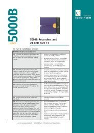
nanodac RECORDER/CONTROLLER: USER GUIDE1 INTRODUCTIONThis document describes the installation, operation and configuration of a paperless graphic recorder/controller.The instrument comes, as standard with four input channels and is equipped, for secure archivingvia FTP transfer and/or to USB memory stick.1.1 UNPACKING THE INSTRUMENTThe instrument is despatched in a special pack, designed to give adequate protection during transit.Should the outer box show signs of damage, it should be opened immediately, and the contents examined.If there is evidence of damage, the instrument should not be operated and the local representativecontacted for instructions. After the instrument has been removed from its packing, the packing should beexamined to ensure that all accessories and documentation have been removed. The packing should thenbe stored against future transport requirements.2 INSTALLATIONCAUTIONBefore installation, ensure that the specified instrument supply voltage matches the facility supply.2.1 MECHANICAL INSTALLATIONFigure 2.1.1 gives installation details.2.1.1 Installation Procedure1. If it is not already in place, fit the IP65 sealing gasket behind the front bezel of the instrument.2. Insert the instrument through the panel cutout, from the front of the panel.3. Spring the retaining clips into place, and secure the instrument by holding it firmly in place whilst pushingboth clips towards the rear face of the panel.4. The protective membrane can now be removed from the display.Retaining spring (two places)For the sake of clarity, the panelis shown as though transparentPush springs towards panel2.1.2 DemountingFigure 2.1.1 Securing the InstrumentWARNINGBefore removing the supply voltage wiring, isolate the supply voltage and secure it against unintendedoperation.1. Isolate the mains supply and secure it against accidental operation. Remove all wiring and the USBdevice and Ethernet cable (if any).2. Remove the retaining springs by unhooking them from the sides using a small flat-blade screwdriver.3. Pull the instrument forwards out of the panel.Note: See “C1 BATTERY REPLACEMENT” on page 327 for a more detailed descriptionHA030554Issue 7 Nov 12Page 3
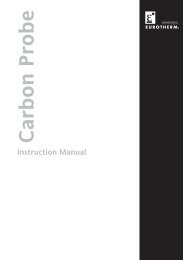
nanodac RECORDER/CONTROLLER: USER GUIDE2 Mechanical Installation (Cont.)Side ViewPanel cutout:92mm x 92mm (both -0 + 0.8mm)3.62in x 3.62in (both -0.00 + 0.03in)Minimum inter-unit spacing:Horizontal (‘x’) = 10mm (0.4in)Vertical (‘y’) = 38mm (1.5in)Top ViewFigure 2.1a Mechanical installation details (standard case)Page 4HA030554Issue 7 Nov 12
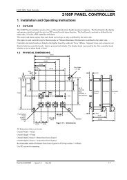
nanodac RECORDER/CONTROLLER: USER GUIDE2.1 Mechanical Installation (Cont.)Side ViewPanel cutout:92mm x 92mm (both -0 + 0.8mm)3.62in x 3.62in (both -0.00 + 0.03in)Minimum inter-unit spacing:Horizontal (‘x’) = 10mm (0.4in)Vertical (‘y’) = 38mm (1.5in)Top ViewFigure 2.1b Mechanical installation details (wash down case option)2.2 ELECTRICAL INSTALLATIONFigure 2.2 shows the locations of the various user terminations along with signal and supply wiring pinouts.2.2.1 Termination detailsThe screw terminals accept single wires in the range 0.21 to 2.08 mm 2 (24 to 14 AWG) inclusive, or two wireseach in the range 0.21 to 1.31 mm 2 (24 to 16 AWG) inclusive.Screw terminals should be tightened to a torque not exceeding 0.4Nm (3.54 lb in)HA030554Issue 7 Nov 12Page 5
nanodac RECORDER/CONTROLLER: USER GUIDE2.2 ELECTRICAL INSTALLATION (Cont.)81100 to 230Vac±15%;50/60 HzBrownBlueMains (Line) supply voltage wiringSupplyVoltageSafety EarthI/O120.4 to 28.8Vac;48 to 62 Hz or19.2 to 26.4V dc(polarity irrelevant)Low voltage option supply voltage wiringR>500R = inactiveR600R = inactiveR
nanodac RECORDER/CONTROLLER: USER GUIDE2.2.2 Low Voltage OptionThis option allows the use of a low voltage ac or dc 24 V supply. The specification in Appendix A gives fulldetails. The polarity of the dc supply connection is not important - it may be connected either way round.2.2.3 Dual Input OptionThis is a cost option, enabled on a channel-by-channel basis by means of entering the relevant password inthe ‘Feature3 Pass’ field in Instrument.Security menu described in Section 4.1.6.For each enabled channel, a pair of thermocouple, mV or mA inputs can be connected to the instrument.These inputs are called ‘primary’ and ‘secondary’, and are terminated at the analogue input terminals (AnIn1 to An In 4) as shown in ‘figure 2.2, above. The primary inputs 1 to 4 are assigned to channels 1 to 4, asnormal. Each secondary input must be soft wired to a maths channel configured as Operation = ‘Copy’ if itis to be recorded/displayed/alarmed etc.Note: Due to the nature of the input circuit, a large offset may appear for secondary thermocoupleinputs. This offset can be removed only by using the input adjust feature described in Section 4.1.9Because of this offset, the dual thermocouple input option is not suitable for AMS2750D applicationsSoft wiring is described in Section 7Maths channels are described in Section 4.5.1Channel configuration is described in Section 4.4.1Input adjust is carried out as described in Section 4.1.9SAMPLE RATEFor dual input channels, both primary and secondary sample rate is reduced to 4 Hz (250ms) from the normal8Hz (125ms).SENSOR BREAK DETECTIONInput sensor break detection is not supported for secondary inputs. The internal circuit acts as a ‘pull up’ onthe secondary input which therefore saturates high in the event of a sensor break.DUAL MILLIAMP OFFSET CORRECTIONIf ‘Dual mA’ is selected as input type, then an automatic offset correction will be made, according to the shuntvalue entered in channel configuration.INPUT RANGE LIMITATIONThere is no 10V range associated with the secondary input. Any input greater than +2V or less than -2V isdeemed to be ‘bad range’.2.2.4 Modbus Master communicationsThe master instrument can be connected directly to up to two slaves using standard ethernet network cableeither directly (single slave only) or via a hub or switch (one or two slaves). In either case, ‘straight through’or ‘crossover’ cable may be used. The cable is terminated at the RJ45 socket at the rear of the unit.2.2.5 EtherNet/IPThe Client and Server are connected in the same way as described above for Modbus Master communications,except that there can be only one client and one server.HA030554Issue 7 Nov 12Page 7
nanodac RECORDER/CONTROLLER: USER GUIDE3 OPERATIONOn power up a default or customsplash screen appears and remains visible whilst the unit is initialising.If during this process a network broadcast storm is detected, the unit stops, displaying anetwork failure icon until the broadcast storm has cleared, after which the initialisation processresumes.3.1 INTRODUCTIONThe operator interface consists of a display screen and four push buttons.3.1.1 Display ScreenThe display screen is used both to display channel information (in one of a number of display modes), andto display the various configuration screens which allow the user to setup the recorder to display the requiredchannels, to set up alarms and so on. Display modes are described in Section 3.4 below; configurationis described in Section 4.In display mode, the screen is split horizontally into three areas (figure 3.1.1)1. a faceplate giving channel details.2. the main display screen showing channel traces etc.3. the status area, displaying instrument name, the current time and date and any system icons.FaceplateChannel 1 6.23VMain display screenStatus areaInstrument name12:01:08Figure 3.1.1 Display mode screen (vertical trend)In configuration mode, the entire display screen is devoted to the selected configuration menu.3.1.2 Navigation PushbuttonsHomeConfigurationGo to ViewHistoryFaceplate cycling (On)Operator NotesDemand ArchivingLog outFigure 3.1.2 Top level menu (Engineer level access)There are four navigation buttons, called ‘Page’, ‘Scroll’, ‘Lower’ and ‘Raise’ located below the screen. Thegeneral properties of these buttons are described in the remainder of this section, but some have additional,context sensitive functions, which, for the sake of clarity are not described here but in the relevant sections(e.g. ‘Message summary’) of the manual.Page 8HA030554Issue 7 Nov 12
nanodac RECORDER/CONTROLLER: USER GUIDE3.1.2 Navigation Pushbuttons (Cont.)PAGE BUTTONFrom any non-configuration page, pressing this push button causes the top level menu (figure 3.1.2) to appear.The figure shows the menu for a user logged in with ‘Engineer’ level access. Other access levels mayhave fewer menu items.Within configuration pages, the Scroll button can be used as an enter key to select lower menu levels. In suchcases the page button is used to reverse this action, moving the user up one menu level per operation.SCROLL BUTTONFrom trending pages, operation of the scroll push-button scrolls through the channels enabled in the group.The Faceplate cycling ‘Off’ selection can be used to keep a particular channel permanently displayed, andthe scroll pushbuttons can then be used to select channels manually.In configuration pages, the scroll key operates as an ‘enter’ key to enter the next menu level associated withthe highlighted item. Once the lowest menu level is reached, operation of the scroll key allows the value ofthe selected item to be edited by the relevant means (for example, the raise/lower keys, or a keyboard entry).The ‘Page’ key is used to move the user back up the menu structure, until the top level menu is reached,when the scroll key can be used again to return to the Home page.The scroll button is also used to initiate user wiring as described in Section 7.RAISE/LOWER BUTTONSWithin trending displays, the Raise and Lower keys can be used to scroll through the enabled display modesin the sequence: vertical trend, horizontal trend, vertical bargraph, horizontal bargraph, numeric, verticaltrend... and so on.Within configuration pages, these pushbuttons act as cursor keys, allowing, for example, the user to highlightmenu items for selection using the scroll button, and in many cases allowing the user to select one froma number of alternative values within menu items. These keys are also used to navigate through the virtualkeyboards (Section 3.6) and number pads used to enter text or numeric strings.3.1.3 On Screen HelpThe top level configuration menu includes contextual help text on the right-hand half of the screen. Mostlythis text fits within on screen height. Where this is not the case, the text can be moved up or down the screenby holding the Page button operated whilst using the up and down arrows to move the text.The down arrow moves the text upwards on the screen; the up arrow moves it downwards.Select configuration menuLogic (2 Input)Logic (8 input)MultiplexerMath (2 input)Timer<strong>User</strong> valuesAlarm SummaryThe timer functionblock offers a universaltimer which may bere-configured betweensingle pulse outputsand re-triggeringoutputs. Timer typesare:On pulse on-timer.On-screen help.(Use the Page button with thedown arrow to access hiddentext at the bottom of the screen)+Figure 3.1.3 On-screen help (typical)HA030554Issue 7 Nov 12Page 9
nanodac RECORDER/CONTROLLER: USER GUIDE3.2 PROCESS VARIABLE DISPLAYAs discussed above, the operator interface consists of a display screen and associated push buttons. Thedisplay screen shows process variables in one of a number of formats, or operational details (notes or alarmhistory for example), or configuration details for use in setting up the recorder to produce the required displaysand history formats. The remainder of section three discusses the process variable displays, alarm displaysand so on; configuration details are to be found in Section 4.Note: Some of the items below can be selected for use only by users with a suitable permission levelas set up in the ‘Instrument’ ‘Security’ menu described in Section 4.1.6.Figure 3.2 below, depicts a typical trend display and gives details of the various areas of the display page.Current point nameCurrent point ‘pen’Channel 1 6.23VCurrent point value and unitsCurrent point scaleTime/date stampsInstrument nameRecording statusInst name12:01:08Figure 3.2 Typical display screen (Vertical trend)Current time/dateFigure 3.2 shows a vertical trend page. Operating the Raise/Lower push-buttons allows the user to scrollthrough the other display modes: Horizontal trend, Vertical bargraph, horizontal bargraph, numeric, verticaltrend... and so on. All these display modes are described in Section 3.4, below.A display mode can also be selected from the Top level menu ‘Go To View’ item which appears when the‘Page’ key is operated.The scroll button can be used to scroll through the points in the group, overriding the ‘Faceplate Cycling’on or off selection3.2.1 Alarm IconsNotes:1. A full discussion of alarms is given in the Channel Configuration section of this manual (Section4.4.3)2. Trigger alarms do not display threshold marks or bars, or faceplate symbolsThe alarm icons shown below appear in some display modes. The icons on a channel faceplate show thestatus of that channel’s alarm(s), as follows:Icon is flashingalarm is active but unacknowledged or it is an Auto alarm which is no longer activebut which has not been acknowledgedIcon steadily illuminated the alarm is active and has been acknowledged.Alarm thresholds and deviation alarm bars appear for horizontal and vertical trend modes. For deviationbars, the bar stretches from (Reference - Deviation) to (Reference + Deviation). Vertical and Horizontal bargraphmodes display only absolute alarm symbols.Page 10HA030554Issue 7 Nov 12
nanodac RECORDER/CONTROLLER: USER GUIDE3.2.1 Alarm Icons (Cont.)Absolute HighAbsolute LowDeviation HighDeviation LowDeviation BandRising Rate of changeFalling Rate of changeDigital HighDigital LowTable 3.2.1 Alarm icons3.2.2 Status Bar IconsThe following items can appear in a dedicated window immediately to the left of the time and date, at thebottom right-hand corner of the display. The width of this window expands as the number of icons increases,and the instrument name is truncated, as necessary, to make room.SYSTEM ALARMSThis indicator appears, flashing, if any one or more of the alarms listed below is active. The System Alarmssummary page (accessed from ‘Go to View in the top level menu) allows the user to view such system alarmsas are active. It is not possible to ‘acknowledge’ system alarmsArchive DisabledArchiving FailedArchiving TimeoutBattery failureBroadcast Storm detectedClock failureChannel errorDatabase failureDHCP Server failureFTP Archiving file lostFTP Archiving to slowAn unattended archiving strategy has temporarily been disabled.An unattended archiving strategy has failed to complete.A configured archiving strategy has timed out.Indicates that the battery is approaching the end of its useful life, orthat it is missing or is completely exhausted. Immediate battery replacementis recommended (Appendix C; section C1).Networking is limited until the storm has passed.The internal clock was found to be corrupt at power up, or that thetime has never been set. Time is forced to 00:00 1/1/1900. Can becaused by battery failure, in which case a battery failure message appears.The error is cleared by setting the time and date.Indicates a hardware failure in the channel circuit or in the internalcold junction temperature measurement.Corrupted EEPROM or flash memory.For units with ‘IP Type’ set to ‘DHCP’ (Network.Interface configuration)this alarm occurs if the instrument is unable to obtain an IP addressfrom the server.A file has been deleted that had not yet been archived. Possible causes:Communications with the server could not be established,; archiveis disabled; archive rate too slow.The archive rate is too slow to prevent the internal memory from overflowing.The recorder effectively switches to ‘Automatic’ (Section4.2.2) to ensure that data is not lost.(Continued)HA030554Issue 7 Nov 12Page 11
nanodac RECORDER/CONTROLLER: USER GUIDE3.2.2 Status Bar Icons (Cont.)FTP Primary Server FailureFTP Secondary Server FailureMaths channel failureMedia archiving file lostMedia archiving to slowMedia fullMedia missingNon-volatile memory failureNon-volatile Write Frequency warningRecording failure (message)USB overcurrentWiring failureThis error occurs if the recorder fails to establish connection with theprimary server, after two attempts. After the second attempt fails, therecorder attempts to establish connection with the secondary serverinstead. Primary and secondary server details are entered in the Network.Archiving area of configuration (Section 4.2.2).This error occurs if the recorder fails to establish connection with thesecondary server, after two attempts. Primary and secondary serverdetails are entered in the Network.Archiving area of configuration(Section 4.2.2).Appears if, for example, the divisor of a divide function is zero.A file has been deleted that had not yet been archived. Possible causes:Memory stick missing, full or write protected; archiving has beendisabled; archiving rate too slow.The archive rate is too slow to prevent the internal memory from overflowing.The recorder effectively switches to ‘Automatic’ (Section4.2.2) to ensure that data is not lost.Archive storage device is full. The alarm becomes active only whenan archive is in progress.No archive storage device present when archive attempted.RAM copy of non-volatile parameters is corrupted.One or more parameters are being written frequently to non-volatilememory. If this continues, it may lead to ‘memory depletion’ (i.e. thememory will no longer be able to store values correctly). A commoncause of this problem is frequent writes over Modbus comms.Message explains reason for failure.USB power fault - too much current (i.e. >100mA) is being drawn by aUSB device.The user wiring has failed to verify, i.e. one or more wires has beendetected that does not have both a source and a destination defined.This may be the result, for example, of power loss during a downloadfrom iTools.CHANNEL ALARMThis indicator appears if any channel (including channels not in the display group) is in an alarm state. Thesymbol is illuminated continuously if all alarms are acknowledged or flashes if any one or more alarms is unacknowledged.Alarms are acknowledged from the Root menu ‘Alarm summary’ item as described in Section3.3.3 or in the Channel configuration area (Section 4.4.3) if the user’s access permission is appropriate.USBThis icon appears whenever a memory stick (max. capacity 8GB) or other supported USB device (Section 8)is plugged into the USB port at the rear of the recorder.When data transfer is in progress between the instrument and the memory stick, the icon changes to a ‘busy’version.CAUTIONThe Memory stick must not be removed while archiving (demand or automatic) is inprogress, as to do so may irreparably damage the file system of the memory stick,rendering it unusable. It is recommended that all archiving be suspended before thememory stick is removed.Memorystick fittedTransfer inprogressFTP ICONThe FTP icon appears whenever transfer activity is taking place.Page 12HA030554Issue 7 Nov 12
nanodac RECORDER/CONTROLLER: USER GUIDE3.2.2 Status Bar Icons (Cont.)RECORD ICONOne of four icons appears at the bottom left corner of the display to indicate recording status.RecordThis indicates that the recorder is recording the items selected in the Group Recording area of configuration(Section 4.3).StoppedThis means that ‘Enable’ has been set to ‘no’ in the Group Recording area of configuration (Section 4.3).Trending is not affected.Paused (Suspended)This means that recording has been paused by a wire to the Suspend parameter (Group Recording area ofconfiguration (Section 4.3) going true (high). Trending is not affected.In ConfigurationThe recorder has been placed in configuration mode either at the user interface, or via iTools. Recording isstopped until the recorder is no longer in configuration mode. For each non-recording state (Stopped,Paused or In Configuration). A new history file is created when the unit comes out of configuration mode.Note: For recording to be enabled, configuration status must be ‘logged out’ both at the instrumentand at iTools.MESSAGE ICONThis ‘envelope’ icon appears when a message is generated and it remains on display until the Message Summaryis accessed, when it is removed from the display until the next new message is generated.AUTOTUNE ICONFor instruments fitted with the Loop option, this symbol appears during the Autotune process.3.2.3 Breaks in recordingBreaks in recording can be caused by the unit being powered down, by the user entering configurationmode or when the recorder time is changed manually. In vertical and horizontal trend modes, a line is drawnacross the width/height of the chart to indicate that recording has been interrupted.On power up, a red line is drawn across the chart. In ‘History’, if messages are enabled the message:Date Time System power upis printed on the chart, together with the configuration and security revisions.On exiting configuration mode, a blue line is drawn on the chart and in ‘History’, if messages are enabled,the messages:Date Time Logged out.Date Time Config Revision: N was N-1 (assuming a configuration change was made)Date Time Logged in as: Engineerappear on the chart.When the instrument time is changed (manually - not through daylight saving action) a green line is drawnon the chart and in ‘History’, if messages are enabled, the message:Date Time Time/Date changedappears on the chart.HA030554Issue 7 Nov 12Page 13
nanodac RECORDER/CONTROLLER: USER GUIDE3.3 TOP LEVEL MENUThis menu appears when the page key is operated from any non-configuration page. The menu items displayeddepend on the access permission of the user. One of the menu items is highlighted, and if the scrollkey is operated, then it is the highlighted item that is ‘entered’.Figure 3.3 shows the top level menu for Engineer level access.Section 3.3.1Section 3.3.2Section 3.3.3Section 3.3.4Section 3.3.5Section 3.3.6Section 3.3.7Section 3.3.8HomeConfigurationGo to ViewHistoryFaceplate cycling (On)Operator NotesDemand ArchivingLog outPage keyScroll keyFigure 3.3 Top level menu3.3.1 HomeOperating the scroll key whilst ‘Home’ is highlighted causes a return to the ‘Home’ page. By default, this isthe vertical trend mode, but the mode can be changed in ‘Instrument. Display’ configuration (Section 4.1.3)3.3.2 ConfigurationOperating the down arrow key highlights the ‘Configuration’ item. Operating the Scroll key enters the configurationsubmenu described in Section 4of this manual.Note: ‘Configuration’ appears only if the user has an appropriate access level.Page 14HA030554Issue 7 Nov 12
nanodac RECORDER/CONTROLLER: USER GUIDE3.3.3 Go to ViewOperating the scroll key whilst the ‘Go to view’ item is highlighted, calls the Go to view submenu (figure3.3.3a). This allows the user to view channel alarms, system alarms, messages or to select a different displaymode.Alarm SummarySystem AlarmsMessage SummaryVertical TrendHorizontal TrendVertical BargraphHorizontal BargraphNumericAlarm PanelControlDual LoopCascadeProgrammerSteriliserPromote ListModbus MasterEtherNet/IPAlarm SummarySystem AlarmsMessage SummaryVertical TrendHorizontal TrendVertical BargraphHorizontal BargraphNumericAlarm PanelControlControl (Dual Loop)CascdeProgrammerSteriliserPromote ListModbus MasterEtherNet/IPFigure 3.3.3a Go to view submenuNotes:1. If an option (e.g. ‘Steriliser’) is not fitted, its display mode does not appear in the list.2. Some display modes must be enabled in Instrument. View configuration (Section 4.1.3) beforethey become available.HA030554Issue 7 Nov 12Page 15
nanodac RECORDER/CONTROLLER: USER GUIDE3.3.3 Go To View (Cont.)ALARM SUMMARYFor each active alarm, this page displays the channel identifier with alarm number (e.g. C1(2) = channel 1;alarm 2), the channel descriptor, the alarm threshold the current process value and an alarm type symbol.To return to the top level menu, operate the Page key.Notes:1. The background colour to the channel ID is the same as that chosen for the channel.2. A prefix ‘C’ in the channel ID means that this is a measuring channel; A prefix ‘V’ means that thisis a virtual channel (i.e. a totaliser, counter or maths channel)Channel ID(Alarm number)Channel descriptorAlarm SummaryC1(2) Furnace 1 temp 1 750.00 798.39C2(1) Furnace 1 temp 3 750.00 763.89C3(1) Furnace 1 temp 2 590.00 603.39C4(1) Furnace 2 temp 1 645.00 630.71Alarm ThresholdChannel current process valueAlarm Type indicatorPage keyScroll keyFigure 3.3.3b Alarm summary page with acknowledge confirmation displayALARM ACKNOWLEDGEMENTTo acknowledge an alarm from this view:1. Use the up and down arrows to highlight the requiredalarmC1(2)C2(1)C3(1)C4(1)Alarm SummaryFurnace 1 temp 1 750.00 763.26Furnace 1 temp 3 750.00 770.01Furnace 1 temp 2 590.00 595.83Furnace 2 temp 1 645.00 644.332. Operate the scroll button. The ‘Acknowledge alarm’window appears.Acknowledge alarm?No C2(1) All3. Use the up arrow to highlight the relevant field (C2(1) in thisexample), or ‘All’ if all alarms are to be acknowledged.Acknowledge alarm?No C2(1) All4. Operate the scroll key to confirm. If the alarm fails to respond,this may be due to the fact that it has been configured as a ‘Manual’ alarm, and the trigger has not yetreturned to a ‘safe’ (non-alarm) state, or it could be that the instrument is in a logged out state.SYSTEM ALARMSOperating the scroll button whilst the ‘System Alarms’ field is highlighted displays a list of all currently activesystem alarms. Section 3.2.2 contains a list of system alarms and their interpretations. To return to the toplevel menu, operate the Page key.A further operation of the scroll button displays a ‘Help Information’ page, giving the reason for the highlightedalarm.Operate the scroll button again to return to the system alarm display.Page 16HA030554Issue 7 Nov 12
nanodac RECORDER/CONTROLLER: USER GUIDE3.3.3 Go To View (Cont.)MESSAGE SUMMARYOperating the scroll key whilst the ‘Message summary’ field is highlighted displays the10 most recent messages.Operating the scroll key whilst a message is highlighted shows the selected message in more detail (andusing the up/down keys allows the other messages to be scrolled through). Whilst in this mode, operatingthe scroll key again, allows the user to choose to jump to the message’s location in trend history mode (Section3.5) or to return to the summary page.By default, the interface is set up such that:1. all message types are included2. the up and down arrow keys cause the highlighted selection to move up or down by one message at atime.Message Summary (All Messages) 9/4720/11/09 08:05:2220/11/09 08:06:37 Inactive: Ch1(Al1)20/11/09 08:06:29 Active: Ch2(Al1)20/11/09 08:06:22 Active: Ch1(Al1)20/11/09 08:06:19 Inactive: Ch2(Al2)20/11/09 08:06:18 Inactive: Ch1(Al2)20/11/09 08:06:09 Inactive: Ch2(Al1)20/11/09 08:06:01 Active: Ch1(Al2)20/11/09 08:05:59 Active: Ch2(Al1)20/11/09 08:05:22 Battery flat less than 5% re20/11/09 08:05:22 Power upBattery flat less than 5% remainingSummaryGo to?HistoryTo Trend Historydisplay (Section 3.5)All MessagesRefreshExit MessagesUse scroll button to scroll through ‘All Messages’,‘System’, ‘Alarm’ and ‘Power Up’. Use page buttonto confirm selection.Use scroll button to return to refreshed MessageSummary page.Use the scroll or page button to return to the toplevel menu.MESSAGE FILTERSAll MessagesSystemAlarmPower upLogin/outFigure 3.3.3c Message summary featuresCauses all messages to be displayed on the screen.Shows only system alarmsShows only channel alarmsShows only power up messagesLimits the display to Log in and Log out events.HA030554Issue 7 Nov 12Page 17
nanodac RECORDER/CONTROLLER: USER GUIDE3.3.3 Go To View (Cont.)DISPLAY MODE SELECTIONUse the up/down arrow buttons to highlight the required display mode.Once the required display mode is highlighted, operation of the scrollbutton causes the recorder to leave the ‘Go to View’ menu and to displaychannel values in the selected mode. See Section 3.4 for a description ofthe various display modes.Alternatively the up and down arrow buttons can be used from any of thedisplay modes to cycle through the available modes in the order listed inthe figure.3.3.4 HistoryNotes:1. If an option (e.g. ‘Steriliser’) is not fitted, its display mode is notavailable for selection.2. Some display modes must be enabled in Instrument. Displayconfiguration (Section 4.1.3) before they become available.This top level menu item allows the user to switch from real-time trendingto review mode, where channel values, messages, alarm triggers etc. canbe viewed back as far as the last significant con.figuration change. Historymode is fully discussed in Section 3.5.3.3.5 Faceplate Cycling on/offAlarm SummarySystem AlarmsMessage SummaryVertical TrendHorizontal TrendVertical BargraphHorizontal BargraphNumericAlarm PanelControlControl (Dual Loop)CascdeProgrammerSteriliserPromote ListModbus MasterEtherNet/IPFor the purposes of this document the channel whose faceplate is currently displayed and whose ‘pen’ symbolis visible is called the ‘Active’ channel.By default, the recorder scrolls through all the channels in the display group, with each channel becomingthe active channel in turn. This top level menu ‘Faceplate Cycling’ item allows the user to inhibit this scrollingaction such that the currently active channel remains active permanently, or until a manual scroll is performedusing the scroll button (or until Faceplate Cycling is re-enabled).‘Faceplate Cycling’ is highlighted by using the up/down arrow buttons. Once highlighted, the status can bechanged from ‘On’ to ‘Off’ or vice-versa using the scroll button. Operation of the ‘Page’ button returns theuser to the trend display.3.3.6 Operator NotesThis area allows up to 10 notes to be created when logged in as Engineer, using either the text entry techniquesdescribed in Section 3.6, or ‘iTools’ described in Section 6. Once logged out, operating the scrollbutton whilst a note is highlighted calls a selection box allowing the user either to send that note to the chart,or to write a Custom Note.CUSTOM NOTEThe Custom Note is written using the text entry techniques described in Section 3.6. Once the note is complete,operation of the page button calls a confirmation display. The down arrow is used to highlight ‘Yes’,and when the scroll key is then operated, the message is sent to the chart. This custom message is not retainedfor further use, so if it is required on a regular basis, it is suggested that one of the Operator Notes 1to 10 be configured (Engineer access level required) so that it may be used instead.Note: Each note can contain up to 100 characters.3.3.7 Demand ArchivingThis allows a user, with a high enough access level, to archive a selected portion of the recorder history, eitherto a ‘memory stick’ plugged into the USB port at the rear of the recorder (Local Archiving), or to a pc, bymeans of the FTP protocol (Remote Archiving). The archived data remains in the flash memory of the instrument.When the flash memory is full, new data causes the oldest file(s) to be discarded.The up and down arrow keys are used to navigate to the required field.Page 18HA030554Issue 7 Nov 12
nanodac RECORDER/CONTROLLER: USER GUIDE3.3.7 Demand Archiving (Cont.)ARCHIVE MENUDemand ArchivingDemand ArchivingArchive ToArchiveSuspend ScheduleCancel AllStatusLast ArchiveUSBNoneNoNoComplete02/11/2011 11:37:09Archive To FTP ServerArchive NoneCancel All NoPri Status CompleteSec Status ConnectingLast Archive 02/11/2011 11:37:09Figure 3.3.7 Demand Archiving menu (Local Archiving on left; Remote Archiving on right)Archive ToArchiveSuspend ScheduleCancel AllLast ArchiveStatusPriStatusSecStatusWith this item highlighted, the scroll button and the up/down arrows can be used to select‘USB’ or ‘FTP Server’.For ‘USB’, the archive will be made to the rear USB memory stick. For ‘FTP Server’ thearchive will be made to the Primary or Secondary server (configured in the Network.Archivearea of configuration described in Section 4.2.2. For more details about remotearchiving, see ‘Remote archiving’, below.In a similar way, select the archive period:None: No archiving to take place. (Not editable when logged out)Last Hour: Archives all files created within the last 60 minutes.Last Day: Archive all files created in the last 24 hours.Last Week: Archives all files created in the past seven days.Last Month: Archives all files created in the past 31 days.Archive All: Archives all the files in the recorder’s history.Bring To Date: Archives all files created or updated since the ‘Last Archive’ date andtime.When set to ‘Yes’, automatic (scheduled) archiving is stopped, once the transfer of thecurrent file is complete. Suspend Schedule must be set to ‘No’ again, to restart the suspendedarchive. Suspend can be used to allow the memory stick to be removed andre-fitted safely.When set to ‘Yes’, this cancels USB archiving activity immediately, or cancels FTP archivingonce transfer of the current file (if any) is complete.Shows the date and time at which the last archive (demand or automatic) was attempted.If a demand archive is requested, or is in operation when an automatic archive istriggered, the automatic archive takes precedence.For Archive to USB only‘Complete’ means that no archiving is currently taking place.‘Transferring’ indicates that an archiving is in progress. Accompanied by an animatedcircular display.‘Suspended’ means that archiving has been suspended as requested.For Archive to FTP Server only, this shows the transfer status between the instrumentand the primary host computer.For Archive to FTP Server only, this shows the transfer status between the instrumentand the secondary host computer.HA030554Issue 7 Nov 12Page 19
nanodac RECORDER/CONTROLLER: USER GUIDE3.3.7 Demand Archiving (Cont.)FTP SERVER ARCHIVINGThis allows the archiving of recorder files to a remote computer via the RJ45 type connector at the rear ofthe recorder, either directly or via a network.In order to carry out a successful transfer:1. Details of the remote host must be entered in the Network.Archive area of configuration (Section4.2.2).2. The remote computer must be set up as an FTP server. Help from the user’s IT department may benecessary in order to achieve this. Appendix C, Section C2 to this manual suggests one way, usingFilezilla.3. The remote computer must also be set up to respond to ‘pings’. This is because the instrument pingsthe host whilst establishing connection, and if it does not receive a response the archive attempt fails.When accessing files using Microsoft® Internet Explorer, the address (URL) field can be in one of two formats:1. ftp://. This allows a user to log in as the anonymous user (if the recorder hasany account with the user name set to ‘anonymous’ with a blank password.2. ftp://:@ to log in as a specific user.For IE5 users, Microsoft® Internet Explorer displays, by default, history files only. To quit the history folder,either uncheck the Tools/Internet Options/Advanced/Browsing/’Enable folder view for FTP sites’ option, orcheck the Tools/Internet Options/Advanced/Browsing/’Use Web based FTP’ option.REVIEW SOFTWARE‘Review’ is a proprietary software package which allows the user to extract ‘archive’ data from one or moresuitable instruments* and to present this data on a host computer, as if on a chart, or as a spreadsheet. Thehost computer must be set up as an ftp server (see Appendix C section C2 for a description of one way ofdoing this).As described in the Review help system, ‘Review’ allows the user to set up a regular transfer of data (usingftp) from connected instruments into a database on the pc, and then from this database to the chart orspreadsheet. The chart/spreadsheet can be configured to include one or more ‘points’ from one or all connectedinstruments (where a ‘point’ is an umbrella term for channel, totaliser, counter etc.).It is also possible to archive instrument history files to a memory stick, Compact Flash card etc. (dependingon instrument type) and to use this to transfer the data to the pc.Each type of instrument has its own remote user name and password configuration - for this instrument, theuser name and password are both ‘history and they are not editable.*Suitable instruments are connected instruments, the archive files of which have the suffix ‘.uhh’.3.3.8 LoginLogin allows the user to enter a password in order to gain access to areas of the unit’s configuration whichare not available when the user is logged out.LOGGED OUT ACCESS LEVELLogged out mode allows the user to select viewing mode, to view history, to view alarms, to toggle faceplatecycling on and off, to send notes, to suspend/resume USB archiving and to access the login process.OPERATOR ACCESS LEVELIn addition to the logged out features, Operator access level allows the user to acknowledge alarms, to editnotes and to perform demand archive operations.By default, no password is required in order to enter Operator level, but a password can be set either at Supervisorlevel or at Engineer level.Page 20HA030554Issue 7 Nov 12
nanodac RECORDER/CONTROLLER: USER GUIDE3.3.8 Login (Cont.)SUPERVISOR ACCESS LEVELIn addition to the logged out level function, this access level allows the user to view the recorder’s configuration,and to edit some values (such as alarm thresholds). By default, there is no password required to enterSupervisor level, but a password can be set in the Instrument area of configuration, either at Supervisor levelor at Engineer level.ENGINEER ACCESS LEVELThis allows full access to all areas of the recorder configuration. The default password is 100, but this can beedited in the Instrument area of configuration (Section 4.1.5).Note: recording is stopped for as long as the user is logged in at Engineer level,even if the recorder is not being configured. This is indicated by the Record icon atthe bottom left corner of the process value display screen being replaced by theConfiguration (wrench) icon.LOGIN PROCEDUREFrom the top level menu, use the up or down arrow keys as often as necessary in order to highlight ‘Login’,and then operate the Scroll key to produce the ‘Access Logged out’ display.Note: this procedure describes how to login to an access level with a password associated with it.For non-password protected logins, the user needs only to select the required access level, andpress the scroll key.To log in as Engineer(password = 100):Record iconConfigurationicon1. Operate the uparrow key threetimes, to display‘Engineer’.AccessAccessLogged outOperatorPassword2. Press the scrollkey to call the‘alpha’ keyboard,with the letter ‘q’highlighted.3. Use the downarrow key threetimes to highlight‘Numeric’.Access SupervisorAccess EngineerAccess EngineerPasswordPassword4. Operate the scroll key to display the numeric keyboard(numeral ‘1’ highlighted.)5. Operate the scroll key to enter ‘1’, then use the up arrowkey nine times to highlight numeral ‘0’ and use the scrollkey twice to enter ‘0’ 0’, completing the password of 100.Accept changesCancel No Yes6. Use the Page key to call the confirmation display.7. If the password entry is as required, use the up arrow twice (or the down arrow once) to highlight theword ‘Yes’ and operate the scroll key to confirm. The top level configuration menu appears. Otherwise,‘Cancel’ can be used to clear the entry in order to start again, or ‘No’ can be used to quit login.HA030554Issue 7 Nov 12Page 21
nanodac RECORDER/CONTROLLER: USER GUIDE3.4 DISPLAY MODESThe following subsections describe the various display modes available to the user. By default, the ‘Home’display mode is ‘Vertical Trend’, but this can be edited as a part of ‘Instrument.Display’ configuration. Thisconfiguration area also allows the user to disable one or more display modes should they not be required.The current display mode can be chosen either by using the top level menu ‘Go to View’ item or, from anydisplay mode, by scrolling through the enabled modes using the up or down arrow button.Details of the various display modes are to be found in the following subsections:Vertical trend ................. Section 3.4.1Horizontal trend ............ Section 3.4.2Vertical bargraph .......... Section 3.4.3Horizontal bargraph ..... Section 3.4.4Numeric.......................... Section 3.4.5Alarm panel ................... Section 3.4.6Control loop 1/2............ Section 3.4.7Cascade..............................................Section 3.4.8Programmer (inc. future trend)........Section 3.4.9Steriliser..............................................Section 3.4.10Promote list ........................................Section 3.4.11Modbus Master .................................Section 3.4.12EtherNet/IP.........................................Section 3.4.133.4.1 Vertical TrendIn this mode, channel values are traced as though on a chart rolling downwards (i.e with the latest data at thetop). The chart speed, and the number of major divisions are configured in the ‘Group.Trend’ area of configuration(Section 4.3.1). By default, the chart background is black, but this can be changed to white or greyin the ‘Instrument’ ‘Display’ area of configuration (Section 4.1.3).FaceplateCurrent point nameCurrent point scaleCurrent trace ‘pen’Channel 1 6.23VCurrent point valueTime/date stampRecording symbolInst name12:01:08Current time/dateInstrument nameStatus iconsFigure 3.4 Vertical trend mode display elementsOne of the channels is said to be the ‘current’ or ‘scale’ channel. This channel is identified by its pen iconbeing displayed, and by the channel descriptor, dynamic value and its scale being displayed on a ‘faceplate’across the width of the display, above the chart.Each channel in the Group becomes the ‘current’ channel in turn, for approximately five seconds -i.e. thechannels are cycled through, starting with the lowest numbered channel. Once the final channel in theGroup has ben displayed for five seconds, the first channel is returned-to and the process repeats. Thisscrolling behaviour can be enabled/disabled from the top level menu ‘Faceplate Cycling (Off)’ item describedin Section 3.3.5.The scroll button can be used to cycle through the channels manually in both Faceplate cycle on and offmodes.Use of the up arrow button causes the next enabled display mode to be entered (default = horizontal trend).The page key calls the top level menu.Page 22HA030554Issue 7 Nov 12
nanodac RECORDER/CONTROLLER: USER GUIDE3.4.2 Horizontal Trend modeThis view is similar to the vertical trend mode described in section 3.4.1 above, except that the traces areproduced horizontally rather than vertically. Initially, as each channel appears, its scale appears at the leftedge of the display (as shown below), but in order to show the maximum amount of trend data, the scale isoverwritten after a few seconds.By default, after a few seconds, the‘chart’ expands leftwards to hidethe scale. This feature can be disabledin the Instrument.Display areaof configuration (Section 4.1.3,H.Trend scaling) so that the scale ispermanently on display.Channel 1 6.23VInst nameFigure 3.4.2 Horizontal trend display modeNote: Timestamps appear to the right of the gridline to which they relateUse of the up arrow button causes the next enabled display mode to be entered (default = vertical bargraph).Use of the page key calls the top level menu.3.4.3 Vertical Bargraph modeThis display mode shows the channel values as a histogram. Absolute alarm threshold values appear as linesacross the bars, grey if the alarm is not triggered; red if the alarm is triggered. Alarm symbols appear foractive alarms.Bargraph widths for four to six channels divide the width of the display screen equally between them. Forone and two channels, the width is fixed, and the bars are centred on the screen. Figure 3.4.3 shows someexamples (not to the same scale).Full scale valueActive alarm symbolAlarm threshold (active)Channel 1 35.40V2 channelsAlarm threshold (non-active)‘Zero’ valueInst nameFigure 3.4.3 Vertical bargraph display mode1 channelUse of the up arrow button causes the next enabled display mode to be entered (default = horizontal bargraph).Use of the page key calls the top level menu.HA030554Issue 7 Nov 12Page 23
nanodac RECORDER/CONTROLLER: USER GUIDE3.4.4 Horizontal Bargraph modeSimilar to the Vertical bargraph mode described in Section 3.4.3, above, but includes channel descriptors.The scroll button togglesthe text between pointdescriptor (as shown) andpoint value.Furnace 1 temp 12Channel 2Channel 3Channel 4Furnace 1 temp 122 channelsChannel 2Inst nameVirtualChan 1VirtualChan 21 channelFurnace 1 temp 12Figure 3.4.4 Horizontal bargraph modeUse of the up arrow button causes the next enabled display mode to be entered (default = numeric).Use of the page key calls the top level menu.3.4.5 Numeric modeShows the enabled channels’ values along with their descriptors and with indications of the type(s) of alarmconfigured for each channel.Furnace 1 temp 12Channel 4Alarm type indication(table 3.2.1)Channel 2VirtualChan 1Channel 3VirtualChan 2Figure 3.4.5a Numeric display mode (six enabled channels)The figure above shows an example where the Trend group contains six channels. Figure 3.4.5b shows howthe display appears for trend groups with fewer than six channels configured.6 channels 5 channels 4 channels3 channels 2 channels 1 channelFigure 3.4.5b Display layout for different numbers of channelsThe up arrow button returns to the vertical trend display mode; the page key calls the top level menu.Page 24HA030554Issue 7 Nov 12
nanodac RECORDER/CONTROLLER: USER GUIDE3.4.6 Alarm panelThis display appears only if enabled in the Instrument Display configuration (Section 4.1.3) Alarm panelmode shows current value and alarm status for each channel enabled in the Trend Group. The status isshown in two ways, by the colour of the relevant bar, and by the alarm status indicators.Red barAlarm 2 is active, or alarm 1and alarm 2 are both active.Amber barAlarm 1 is active for thischannel, but not alarm 2.Green barNeither alarm 1 nor alarm twoactive for this channel.Inst nameFigure 3.4.6a Alarm panel display (six channels)Alarm type indication (table 3.2.1)The figure above shows an example where the Trend group contains six channels. Figure 3.4.6b shows howthe display appears for trend groups with fewer than six channels configured.6 channels 5 channels 4 channels3 channels 2 channels 1 channelFigure 3.4.6b Alarm panel display layouts for trend groups with fewer than six channelsHA030554Issue 7 Nov 12Page 25
nanodac RECORDER/CONTROLLER: USER GUIDE3.4.7 Control Loop1/Loop2These displays appear only if the controller option is enabled (Section 4.1.6).The loop display modes are interactive, in that the setpoint, the Auto/Manual mode and the Manual Outputvalue can be edited from the user interface. Full configuration is carried out in the Loop setup menus (Section4.6) and a fuller description of control loops is to be found as Appendix B to this manual.Figure 3.4.7 depicts a single loop display and the dual loop display. The up and down arrow keys are usedas normal to scroll through Loop1, Loop2 and Dual loop pages.Loop 1°CPVLoop 1SP1Mode ManualMan OpPVWSPPVSPWSPWSPWorking OutputSP1ModeMan OpManualLoop 2SP1ModeMan OpManualPVWSPInst nameInst nameFigure 3.4.7 Loop displaysEDITING TECHNIQUESNote: The colours associated with the loops are those of the channels to which they are wired.1. With the loop page on display, operate the Scroll key. This highlights the firsteditable item (SP1). The scroll order includes both loop1 and loop 2 parametersin the dual loop display.SP1Mode ManualMan Op2. Use the up and down arrow keys to select the required field for editing. Whenthe required field is highlighted, operate the scroll key again, to enter edit mode.SP1Mode ManualMan OpSP1Mode ManualMan Op3. Use the up/down arrows to edit the current setting.SP1Mode AutoMan Op4. Operate the scroll key to confirm the edit.5. Select a further parameter for editing, or operate the page key to return to normaloperation.SP1Mode AutoMan OpNote: Edit permissions for Setpoint, Auto/Manual and Manual Output Access are set in the LoopSetup configuration menu (Section 4.6.2).Page 26HA030554Issue 7 Nov 12
nanodac RECORDER/CONTROLLER: USER GUIDE3.4.8 Cascade Display ModeThis display mode appears only if ’Cascade’ has been enabled in the Instrument.Display area of configurationSection 4.1.3). See also Advanced Loop configuration (Section 4.7).MasterModeSp1CascadePVWSPSlaveSPMan.OPPVWSPInst nameFigure 3.4.8a Cascade display modeOperating the scroll button highlights the Master ‘Mode’ field. Operating the scroll button again, enters editmode allowing the user to use the up/down arrow buttons to scroll through the available modes. Once therequired mode appears, a further operation of the scroll button confirms the entry and quits edit mode.Once out of edit mode, the down arrow key can be used to select Master ‘SP1’, Slave ‘SP’ and Slave ‘ManOP’. The Mode selected determines how many of these items are editable by the operator.ModeCascade: The master loop is in auto mode and provides the slave setpoint. Changingmodes causes the slave to switch to the local slave setpoint.Slave: A simple single loop controlling with a local setpoint.Manual: Provides a single manual % power output.SP1Setpoint 1 is the primary setpoint of the controller. If the controller is in automatic controlmode, then the difference between the setpoint and the process variable (PV) iscontinuously monitored by the control algorithm. The difference between the two isused to produce an output calculated to bring the PV to the setpoint as quickly as possiblewithout causing overshoot.SPThe slave setpoint, either local (Manual or Slave mode) in which case it can be edited,or supplied by the master loop (Cascade mode), in which case it is not editable.Man.OP The percentage output power to be applied when in Manual mode (100% = full on; 0%= off).Note: The default loop names (‘Master’ and ‘Slave’) can be replaced by user-entered strings of upto 10 characters in Advanced Loop Setup configuration (Section 4.7.2).HA030554Issue 7 Nov 12Page 27
nanodac RECORDER/CONTROLLER: USER GUIDE3.4.9 Programmer Display ModeProgram status Program editProgram Name (Segment name)Program Name (Segment name)PVPVPVRampPSPEvents:PSPStatus: RunningPSPEvents:Mode RunCh1 PSP 123.2Ch1 TSP 140.0Status:Seg Time LeftCh1 RateRunning00:00:441Mode RunCh1 PSP 123.2Ch1 TSP 140.0Seg Time LeftCh2 PSPCH2 TSP00:01:0512.713.000:00:30 00:02:1200:01:30 00:03:12ProgramprogressSegmentprogressProgram timeremainingDouble channelSingle channelFigure 3.4.9a Programmer displays (typical)This display mode (if enabled - see Section 4.1.3 allows the user to monitor the progress of a single or dualchannelsetpoint program, and if logged-in as ‘Operator*’, to reset or run the program. The program itselfis created in the Program edit page (described below) and in Programmer configuration (Section 4.8 or‘iTools’).*Note: Operator is the default access level - to edit, see ‘ Prog Mode Access’ in Section 4.8.3)The displays contain the following features:Program name This is the name of the loaded program. If the program has been modified since beingsaved, an asterisk (*) appears after the name. Default background colour shown. Thiscolour changes to that assigned to the input channel when this is configured.Segment name This is the name of the current segment. If not named in Segment configuration, thenthe segment number appears instead.Program status At the top right hand corner of the display, this can be any one of the following:The program is running (or ran last time) without any PV ‘Alarm’ events or user intervention.The user has intervened in the running of the program, by placing it in ‘hold’ or ‘reset’,or by advancing a segment, or by adjusting a duration, target setpoint, ramp rateor time-to-target value.A PV ‘Alarm’ Event has activated. A PV ‘Alarm’ Event is an absolute high/low or adeviation alarm on the PV input.There is no program loaded, or if a program is loaded, it has not yet run.Program edit This icon appears for users with appropriate access permissions, to indicate that setpointprograms can be configured (as described in Program edit, below).Segment type For single channel displays, this indicates the type of segment currently being run:Dwell. The segment value remains constant for the duration of the dwell period.End (dwell). Displayed on completion of the program. The segment value remainsat the final value until resetEnd (reset). Displayed on completion of the program. The program resets.Ramp. The segment value ramps at a fixed rate or over a fixed period to the Targetsetpoint. Ramp up icon shown; ramp down is similar but inverted.Step. The segment value switches immediately to the new Target setpoint. Stepdown shown; step up similar but inverted.Wait. The segment value remains constant until the wait criteria are satisfied.Page 28HA030554Issue 7 Nov 12
nanodac RECORDER/CONTROLLER: USER GUIDE3.4.9 Programmer Display Mode (cont.)PVCh1(2)PSPCh1(2)TSPEventsModeStatusCh1 RateCh1 TimeSeg Time LeftProgram progressSegment progressThe current process value of the signal wired to Ch1(2) PV Input.This is the output setpoint from the programmer for the channel. In reset this valuetracks the configured servo parameter.The channel target setpoint. The target set-point may be edited while the program isin hold (in such cases, for ramp rate segments the time remaining is recalculated.Up to eight events can be configured in the Program Edit page. Any one or more ofthese events may be deemed to be active for the duration of each individual segment.Shows the current run mode of the program. If the user has the correct access level, themode can be set to ‘hold’, reset’ etc. by using the scroll key twice (first to highlight therun mode, then again to enter edit mode) and then using the up/down arrow keys toselect the required mode. Run, reset, hold etc. can also be selected by inputs from otherparameters, switch inputs etc.Shows the status of the current segment.The channel 1 rate-of-change of segment value for ‘Rate’ ramp segments.Shows the channel 1 duration configured for the segment to ramp, dwell etc. for ‘Time’ramp segments. For two-channel programs, see the note below.Shows the time that the segment has to run before completion.The numerals show program elapsed time, and the bar gives an indication of progressso far. For two-channel programs, see the note below.For each segment as it runs, this gives a visual indication of the proportion of total segmenttime which has elapsed so far. For two-channel programs, see the note below.Program time remainingShows the time remaining until the program completes. For two-channel programs, seethe note below.Note: For two-channel programs, in ‘Hold’ mode, the ‘program progress’, ‘segment progress’ and‘program time remaining’ areas of the display are replaced by ‘Ch1 Time’ and ‘Ch2 Time’, as shownbelow.Program Name (Segment name)PVPSPPVPSPStatus: HoldingModeCh1 PSPCh1 TSPCh1 TimeHold123.2140.000:00:34Events:Seg Time LeftCh2 PSPCH2 TSPCh2 Time00:01:0512.713.000:00:49Figure 3.4.9b two channel program in Hold modeHA030554Issue 7 Nov 12Page 29
nanodac RECORDER/CONTROLLER: USER GUIDE3.4.9 Programmer Display Mode (cont.)PROGRAM RUN/RESET/HOLDPrograms can be controlled by users with the correct access level (defined in Programmer configuration -Section 4.25). The display page is placed in edit mode by operation of the scroll key (‘Mode’ highlights). Asecond operation of the scroll key followed by operation of the up/down arrows allows the user to select‘Run’, ‘Hold’ or ‘Reset’. A further operation of the scroll key initiates the selected action.ProgramNamePVReset14.3Reset15.7RampPSPMode ResetCh1 PSP 14.3EventsStatus: Reset‘Hold’ appears onlyif the program statusis ‘Running’.Hold18.9Run17.3Figure 3.4.9c Setting the ModeNotes:1. These functions can also be carried out by wiring relevant inputs to the ‘Run’, ‘Hold’ or ‘Reset’ parametersin Programmer configuration (Section 4.8).2. The user must have either ‘Logged off’, ‘Operator’ or ‘Supervisor’ level access as defined in ‘ProgMode Access’ in the Programmer. Setup menu described in Section 4.8.3 . The program cannotrun if the unit is logged into at ‘Engineer’ level.Page 30HA030554Issue 7 Nov 12
nanodac RECORDER/CONTROLLER: USER GUIDE3.4.9 Programmer Display Mode (cont.)PROGRAM EDITINGThe program edit page is accessed by operating the scroll button once to highlight the Mode, then usingthe up arrow key to highlight the page symbol at the top right hand corner of the display and then the scrollbutton again to enter the program editor.Program Name (Segment name)RampMode ResetCh1 PSP 14.3Events:Status: ResetBy default, Program Edit is available only to userswith Supervisor or Engineer level access. The requiredaccess level can be edited in Programmer.Set Up configuration as described in Section4.8.3.Program EditProgram Name (Segment name)RampMode ResetCh1 PSP 14.3Events:Status: ResetOperationStatusProgramHoldback StyleCh1 HoldbackCh1 Holdback ValCh2 HoldbackRamp StyleCh1 Ramp UnitsCh2 Ramp UnitsSelect ...SuccessProgram NameProgramHigh0.0 VOffTimePer SecondPer MinuteSegment NumberSegment Name1Heat InitFigure 3.4.9d Access to the program editorAs can be seen from the figure above, the initial Program Edit page is divided into two areas - the top partcontains program details; the lower part (figure 3.4.9f) contains individual segment details. The editableitems that appear in the program details area depend on the features enabled in the Programmer Featuresconfiguration menu (Section 4.8.1).Note: Access to some program operations is restricted to users with the correct access level, asdefined in the ‘Prog Mode Access’, the ‘Prog Edit Access’ and the ‘Prog Store Access’ parameters inthe Programmer. Set Up area of configuration described in Section 4.8.3. Access to some itemsalso depends on whether or not the program is running.HA030554Issue 7 Nov 12Page 31
nanodac RECORDER/CONTROLLER: USER GUIDE3.4.9 Programmer Display Mode (cont.)PROGRAM DETAILSOperationThis allows the user to select one of the following (see also ‘Program Store):Load. Opens the program store and allows the user to select a program to be loaded.The program must have the same number of channels as defined in Programmer.SetUp (Section 4.8.3).Store. Allows the current program to be saved to the internal program drive. This isuseful if you wish to snapshot the current program and store this under a different programname.Delete. Allows the selected program to be deleted.Delete All. Deletes all programs.Copy. Copies the selected program for ‘pasting’ either from the internal drive to theUSB device, or vice-versa. This is useful if you wish to transfer a program to other nanodacinstruments.Copy All. As above, for ‘Copy’, but copies all the programs in the selected directory.Note: If a ‘Store’, ‘Copy’ or ‘Copy All’ operation would result in there being a total of more than 100program files in the internal drive, the operation fails and an error message is displayed.StatusProgramHoldback StyleCh1 HoldbackCh1 Holdback valueCh2 HoldbackCh2 Holdback valueRamp StyleCh1 Ramp UnitsCh2 Ramp UnitsSuccess. Previous operation was successful.Failed. Previous operation failed.Loading. The program is loading.Copying. The program copy process is underway.Deleting. The relevant program is being deleted.The name of the program currently loaded.Appears only if ‘Holdback’ is enabled in the Programmer Features configuration (Section4.8.1). See also ‘Holdback’, below.Program: Holdback applies to all appropriate segments.Per Segment: Holdback enabled on a segment by segment basis as described in ‘Segmentconfiguration below.Appears only if ‘Holdback Style’ (above) is set to ‘Program’.Off: Holdback is disabledLow: Holdback is entered when PV < (PSP - Holdback Value)High: Holdback is entered when PV > (PSP + Holdback Value)Band: Holdback is entered when PV < (PSP - Holdback Value) or PV > (PSP + HoldbackValue)The value to be used in triggering holdback.As for Ch1 Holdback, above but for channel 2. Appears only if ‘Channels’ is set to ‘2’ inProgrammer Set Up configuration (Section 4.8.3).As for ‘Ch1 Holdback value’, above, but for channel 2. Appears only if ‘Channels’ is set to‘2’ in Programmer Set Up configuration (Section 4.8.3).Ramp style applies to all ramp segments in the program. Ramp Style can be edited onlywhen the program is in Reset mode. Setpoints, rates, times etc. are set in the individualsegment configurationsRate. A Ramp Rate segment is specified by a target set-point and the rate at which toascend/descend to that set-point.Time. A Ramp Time segment is specified by a target set-point and a time in which toachieve that set-point.Select ‘Per Second’, ‘Per Minute’ or ‘Per Hour’ for ramp timing units. Ramp Units can beedited only when the program is in Reset mode.As for ‘Ch1 Ramp Units’ above. Appears only for two channel programs and allows differentramp units to be selected for the two channels, if required. Ramp Units can beedited only when the program is in Reset mode.Page 32HA030554Issue 7 Nov 12
nanodac RECORDER/CONTROLLER: USER GUIDE3.4.9 Programmer Display Mode (cont.)PROGRAM DETAILS (Cont.)HOLDBACKHoldback pauses the program (freezes the Programmer setpoint (PSP) and the time remaining parameters)if the difference between the Process value (PV) and the PSP exceeds a user-specified amount (Holdback value).The program remains paused until the PV returns to within the specified deviation.In ramp or step segments, holdback indicates that the PV is lagging the SP by more than the specifiedamount and that the program is waiting for the process to catch up. In a dwell segment, holdback is usedto guarantee that a work piece stays at set-point within a specified tolerance for the specified dwell duration.PVPSPPSP-Holdback valueHoldback appliedHoldback releasedHoldbackappliedHoldbackreleasedFigure 3.4.9e HoldbackSEGMENT CONFIGURATIONProgram EditSegment NumberSegment NameTypeCh1TSPCh1 TimeCh1 Holdback1Heat initRamp43.358 °C00:10:30HighCh1 Holdback Val 5.0 °CCh1 PVEvent Abs HighCh1 PVEvent Val 58 °CCh1 <strong>User</strong> Val 40.0Ch2TSP 19.5 °CCh2 Time 00:01:00Ch2 <strong>User</strong> val 33.00Event 1Event 2Segment NumberSegment NameFigure 3.4.9f Segment configurationSelect the relevant segment for configuration.Enter a segment name of up to 20 characters. This name will be truncated on the displaypage if it, together with the program name, are too long to fit the width of the displayarea.HA030554Issue 7 Nov 12Page 33
nanodac RECORDER/CONTROLLER: USER GUIDE3.4.9 Programmer Display Mode (cont.)SEGMENT CONFIGURATION (Cont.)TypeSelect a segment type. Default is ‘End’.Ramp. For any program, Ramp segments can be either ‘Ramp Rate’ segments or ‘RampTime’ segments according to the ‘Ramp Style’ setting described above. See also‘Ch1(2) Time’ or ‘Ch1(2) Rate’, below.Dwell. The setpoint is maintained at its current value for the period defined in ‘Duration’(see below).Step. A step segment allows a step change to be entered for the target set-points Ch1TSP and Ch2 TSP.Wait. A wait segment causes the program to wait for a certain event to occur beforecontinuing. See ‘Wait For’, below.Go Back. A Go Back segment allows a specifiable number of iterations to be performedof a group of segments. This could be used, for example, to cycle an entire programby having a Go Back segment immediately before the end segment and specifying segment1 as the ‘Go Back To’ point. Setting ’Cycles’ to ‘Continuous’ causes the programto loop indefinitely, until interrupted by the user. ‘Nested’ loops are not permitted i.e.‘Go Back’ is not available as a segment type for segments inside an existing GoBackloop.End. The final segment of a program allows the user to select ‘Dwell’ or ‘Reset’ as theaction to be taken at the end of the program (see ‘End Type’, below)Ch1(2) TSP Target setpoint. The value that Ramp or Step segments seek to attain, for channel 1(2).Ch1(2) Rate For Ramp Rate segments, this specifies the speed at which the process value ramps towardsthe target, for Channel 1(2). The ramp units (per second, per minute, per hour)are set in Ch1(2) ramp units described above.Ch1(2) Time For Ramp Time segments, this allows the user to specify the time to be taken by the segmentfor the process value to reach the target.DurationFor Dwell segments, this allows the entry of the time for which the segment dwells.Go Back To For ‘Go Back’ segments, this defines the number of the segment to which the programis to return.CyclesThe number of times the ‘Go Back’ instruction is to be carried out. If set to ‘Continuous’,the program continues until the user intervenes to stop it.End TypeAllows the user to select the action to be taken at the end of the program:Dwell: the set-point is maintained indefinitely and event outputs remain at their configuredstate.Reset: the set-point reverts to the value used by the control loop before the programwas started and the event outputs return to their default states.Wait ForDigital High: Wait segments can be configured to wait for ‘Wait Digital’ to go ‘high’ beforeallowing the program to continue.Analog 1(2): The segment waits for ‘Wait Analog1(2) to meet an Absolute High or Low,or Deviation High or Low condition before allowing the program to continue.Analog Both: As Analog 1(2) above, but waits for both Channels’ conditions to be truebefore continuing.Note: ‘Wait Digital’, Wait Analog 1’ and ‘Wait Analog 2’ parameters are configured in the Programmer.SetUp menu described in Section 4.8.3.Ch1 Wait Select ‘Abs High’, ‘Abs Low’, ‘Dev High’ or ‘Dev Low’ as the wait criterion for channel 1.Appears only if ‘Wait For’ (above) is set to ‘Analog 1’ or ‘Analog Both’.Ch2 Wait Select ‘Abs High’, ‘Abs Low’, ‘Dev High’ or ‘Dev Low’ as the wait criterion for channel 2.Appears only if ‘Wait For’ (above) is set to ‘Analog 2’ or ‘Analog Both’.Ch1(2) Wait Val Enter the trigger value for ‘Ch1(2) Wait’Ch1(2) Holdback Select ‘Off’, ‘Low’, High’, or ‘Band’ (see description in Program details above).Ch1(2) Holdback Val The value to be used in triggering holdback.Page 34HA030554Issue 7 Nov 12
nanodac RECORDER/CONTROLLER: USER GUIDE3.4.9 Programmer Display Mode (cont.)SEGMENT CONFIGURATION (Cont.)Ch1(2) PV EventAppear only if ‘PV Events’ have been enabled in the Programmer Features menu (Section4.8.1). A PV Event (an analogue alarm on the channel PV) is available for eachchannel in every segment (excluding Wait and Go Back segment types). The followingPV Events are supported:Off: The PV Event is disabledAbs High: The event is triggered when the channel PV exceeds PVEvent Val for the relevantchannel.Abs Low: Triggered when the channel PV becomes less than PVEvent Val for the relevantchannel.Dev High: This event is triggered when the channel PV exceeds (PSP + PVEvent Val) forthe relevant channelDev Low: Triggered when the channel PV becomes less than (PSP - PVEvent Val) for therelevant channel.Dev Band - This event is triggered when the channel PV differs from the PSP by morethan the configured deviation value (either above or below)In the following example, in segment 1 Ch1 PV Event has been configured as Dev Bandand in segment 2 it has been configured as an Abs low:Segment 1 Segment 2PSPPVPVEven= PV Event Val Segment 1= PV Event Val Segment 2OnOffPV EveFigure 3.4.9g PV EventsCh1 PVEvent ValCh2 PVEvent ValCh1 (2) Event UseCh1 (2) <strong>User</strong> ValEvent 1 to 8Appears only if ‘Ch1 PVEvent’ is not ‘Off’. Sets the level at which Ch1 PV Event becomesactive.Appears only if ‘Ch2 PVEvent’ is not ‘Off’ and if ‘Channels’ is set to ‘2’ in Programmer SetUp configuration (Section 4.8.3). Sets the level at which Ch2 PV Event becomes active.When PV events become active, they can be used either to Trigger a secondary processor as a simple analogue alarm on the PV input. Appears only if the relevant PV Eventparameter is not set to ‘Off’.Specifies the <strong>User</strong> Value for this segment, for channel 1(2). Appears only if ‘<strong>User</strong> Value’has been enabled in the Programmer Features menu (Section 4.8.1).The example below (from iTools) shows this parameter wired to the trigger 1 input ofthe Custom Messages block, so that, if a <strong>User</strong> value >0 is entered, then every time thesegment runs, Custom message 1 is generated.The number of Events available (Max Events) is defined in Programmer Set Up configuration(Section 4.8.3). Enabling an event causes the relevant indicator on the displaypage to be illuminated for the duration of the segment. As with ‘<strong>User</strong> Val’, above,Events can be wired to the inputs of other parameters if required.HA030554Issue 7 Nov 12Page 35
nanodac RECORDER/CONTROLLER: USER GUIDE3.4.9 Programmer Display Mode (cont.)SEGMENT CONFIGURATION (Cont.)Figure 3.4.9h iTools example showing Ch1 <strong>User</strong>Val being used to trigger custom message 1.FUTURE TREND DISPLAY MODEIf enabled in Instrument.Display configuration (Section 4.1.3), this allows the user to view the actual value ofthe PSP alongside the expected value, so the two can be compared to see how the process is performing.Future trend is an enhancement of the horizontal trend mode, with the display being divided into two parts,with the instantaneous current value located at the divide, with past trends to the left and the next few programsegments to come, to the right.Notes:1. For the future trend mode to appear, the programmer must be wired to the loop or advancedloop feature.2. Both historic and future trends move from right to left with the present anchored at the screencentre.3. The amount of history and of future trending displayed on the screen depends on the trend intervalset in Group.Trend configuration (Section 4.3.1)Figure 3.4.9i shows a typical future trend displayPresentChannel 1 26.23VPastFutureInst nameFigure 3.4.9i Future trend displayPage 36HA030554Issue 7 Nov 12
nanodac RECORDER/CONTROLLER: USER GUIDE3.4.9 Programmer Display Mode (cont.)PROGRAM STORENote: The access levels required for the operations described below are configured in the ProgrammerSet Up menu ‘Prog Edit Access’ and ‘Prog Store Access’ parameters, described in Section4.8.3.The program store allows access to the instrument’s local program storage area and to programs stored ona USB memory stick (if any) and to those stored in a pc (if any), via FTP. Programs may be saved to (Stored)or retrieved from (Loaded) from the program store, or they can be copied or deleted.Selecting any of the program operations (except ‘Delete All’), from the Program Edit page (Engineer accesslevel required) opens the file explorer page. Figure 3.4.9j depicts this page, with just a couple of exampleentries after a ‘Load’ operation has been requested.On entry, use the up/down arrow button to select ‘<strong>User</strong>’, ‘USB’ or ‘FTP’ (selection highlights yellow), then usethe scroll button to confirm. Use the up/down arrow buttons to select the required file, and then use thescroll button again to confirm. Other operations are similar.The file explorer supports 100 entries, which may be directories or files.<strong>User</strong>Kiln1.UIPZKiln1 type 2.uipzkiln2.uipzfurnace1 purge.uipzSymbol appears onlyif a suitable USBdevice is insertedSelected filehighlightedFigure 3.4.9j Program store displayNote: A ‘busy’ icon (rotating green flash) appears whilst directory listings are being accessed.HA030554Issue 7 Nov 12Page 37
nanodac RECORDER/CONTROLLER: USER GUIDEPROGRAM LOAD - QUICK ACCESSFrom firmware version V5.00 and above a quick selection of an internally stored program may be made directlyfrom the Program Summary page. The programmer must be in Reset. Press and hold the scroll keyfor 2 seconds. The page will go immediately to the file explorer page with the ‘<strong>User</strong>’ drive selected and the‘Operation’ parameter set to ‘Load’. The first program file will be selected (assuming different programshave been configured). Use the Up/Down keys to select the required program followed by the scroll key toload it.If the selected file cannot be loaded (for example, the programmer file is for a different number of channels)then an error message is shown on the file explorer.The Quick Access to load mode adheres to the access security settings set in configuration mode - Programmerset up (Figure 4.8.3).Note: Quick load is disabled when in Edit mode. This is indicated by the highlighted parameter showingthe raise/lower symbol to the right of its value.PV<strong>User</strong>RampModeCh1 PSPCh1 TSPPSPReset14.3140.0Events:Status:Seg Time LeftCh1 RateReset00:00:4401Press and holdthe Scroll key for 2secondsKiln1.uipzKiln1 type 2.uipzkiln2.uipzfurnace1 purge.uipzFigure 3.4.9k Program load displayPage 38HA030554Issue 7 Nov 12
nanodac RECORDER/CONTROLLER: USER GUIDEPROGRAM LOAD VIA A PROGRAM NUMBERThis feature has been added to firmware versions V5.00 and above.To allow a program (stored as a file) to be loaded, either via a BCD switch, wired to a set of digital inputs, orvia a single comms transaction, it is necessary to prefix the progam name with a program number in therange 01 to 99. For example, 01kiln1.uipz, 01furnace.uipz, 02kiln2.uipz, 03kiln3.uipz etc. The programname can consist of up to 18 characters. Note that program numbers 1 to 9 must be entered as 01 to 09otherwise they will not be recognised by the switch or via comms.On value change of the program number, the first program file with the prefixed number in the instrument’sinternal <strong>User</strong> drive (listed lexographically) will be loaded. In the above example if program 01 is selected,01furnace.uipz will be loaded, 01kiln1.uipz will not be loaded using the BCD switch or through comms. Itcan, of course, be loaded manually.If no program number is prefixed it is not possible to load the program via the BCD switch or via comms. Itis, however, still possible to load the program by selecting the file as described in the previous section.Note: When a BCD switch is turned from its current value to another value, intermediate switch positionsmay be seen on the inputs of the BCD function block and could potentially be used by subsequent blockswired from the BCD input. A Settle Time parameter has been introduced which will in effect filter out theseintermediate values by applying a time in which the inputs can settle before their converted decimal valueis seen on the output parameters of the block. The Settle Time can be set from 0-10seconds with a defaultof 0s i.e. no filtering as in previous firmware versions. The BCD block is described in Section 4.19.EXAMPLE BCD SWITCH WIRINGFigure 3.4.9l below shows an example of using digital input channels soft wired to the BCD function blockusing iTools.Figure 3.4.9l BCD Switch WiringFigure 3.4.9m below shows the corresponding hard wiring of a BCD switch.BCD Switch11A1B2AUSB1I1+1-2C2BLALC3ALB812I2+2-3I43BLC4A3+3-LC5A4I4+8NE4-Figure 3.4.9m BCD Switch Physical WiringHA030554Issue 7 Nov 12Page 39
nanodac RECORDER/CONTROLLER: USER GUIDE3.4.10 Steriliser display modeThis display mode appears only if the Steriliser option is fitted and if the display mode has been enabled inthe Instrument Display configuration (Section 4.1.3). Steriliser configuration parameters are to be found inSection 4.17.Cycle statusCycle number Cycle: 123 EquilibrationInput status beaconsBand HighBand Low (red)Target setpoint (orange)Current input valuesInput 1 Input 2 Input 3 Input 4120.8°C 121.6°C 122.4°C 2885mBRemainingSterilising00.05.0000.00.00Equilibration 00.03.00Total Cycle 00.03.00Note:If any input is configured ‘Off’(in Steriliser configuration), itdoes not appear in the display,and the other inputs occupythe screen width equally.Input status beacons are blackfor inputs configured ‘Off’Figure 3.4.10a Steriliser display mode (typical) (four inputs)OPERATIONA sterilising cycle cannot be initiated whilst the unit is in Configuration (Engineer) mode.A steriliser cycle is started by setting its relevant ‘Start’ input to ‘Yes’ for the duration of the cycle. The cyclewaits (status ‘Waiting’) until input 1 reaches its setpoint, at which point the cycle enters the equilibration period(status ‘Equilibration’), and remains there until all the configured inputs are valid. The cycle then entersthe sterilising period and stays in this mode until the sterilising period has expired (status ‘Passed’) or untilone of the inputs becomes invalid (status ’Failed’) for longer than its configured ‘Failure Dwell’ time.Note: The cycle stops (status ‘Failed’) if the trigger source is removed.TERMINOLOGYHolding timeEquilibration timeBandsMost operating cycles have a stage in which the load must be exposed to sterilisationconditions for a specified length of time, known as the ‘Holding time’.The holding time (above) is preceded by a period during which, although the sterilisingcondition is present in the chamber, the load has not yet attained that temperature dueto its thermal inertia. ‘Equilibration time’ is defined as the time between the attainmentof sterilisation temperature in the chamber, and the attainment of that temperature inall parts of the load.For steam and dry heat sterilisers, sterilisation conditions are specified by a sterilisationtemperature band, defined by a minimum acceptable temperature (known as the sterilisationtemperature) and a maximum allowable temperature. A sterilisation band isnormally quoted for each steriliser type.BEACONSThere are four input status beacons near the top right hand corner of the display, one for each input.During equilibration, the beacons are flashing red for inputs that have not attained the Target setpoint, andgo green when the target setpoint is reached, remaining green even if the input value rises above the BandHigh value The beacons revert to red if input falls below* the target setpoint.During sterilisation, the beacons go red for any input whose value rises above Band High or falls below* setpointfor a duration exceeding the configured ‘Failure Dwell’ period.Beacons are black for inputs that are configured as ‘Off’.* ‘rises above’ for input types ‘Falling Pressure’ or ‘Fall Air Detect’Page 40HA030554Issue 7 Nov 12
nanodac RECORDER/CONTROLLER: USER GUIDE3.4.10 Steriliser Display Mode (Cont.)DISPLAYED INFORMATIONCycleA five-digit counter to indicate the total number of cycles started.StatusWait start: The initial state at power up. This status remains until the first cycle is initiatedWaiting: Waiting for input 1 to reach its target setpoint. The cycle then enters Equilibration.Equilibration: Currently in the equilibration period, during which the cycle waits untilall inputs have reached sterilisation conditions.Sterilising: Currently in the decontamination phasePassed: The cycle has completed successfullyFailed: The cycle has failed either through one or more inputs becoming invalid, or becausethe ‘Start’ signal was removed.Test cycle: A test cycle is in progressRemaining The sterilising time remaining for the current cycle. Display field is replaced by ‘TargetTime’ (below) when the cycle is not running.Target time The intended sterilisation time. This can be configured by operating the scroll buttontwice (once to highlight the field, and again to enter edit mode), and then using the upand/or down arrows to edit the time. Use the Scroll button again to quit edit mode, andthe page key to ‘unhighlight’ the field.Replaced by ‘Remaining’ (above) when the cycle is running.Equilibration The equilibration time period for the current cycleSterilising The time for which the load has currently been at sterilisation conditionsTotal Cycle The elapsed time since the initiation of the current cycle. This time increments from thetime the cycle is triggered until the time the trigger is removed.Input values Temperature are required in °C; pressure inputs in mBar. If necessary, maths channelsand user values can be used to convert from other units (see ‘Note’ overleaf).STERILISING CYCLE DIAGRAMFigure 3.4.10b, below, shows a steriliser cycle in diagrammatic form.Wait StartWaitingEquilibrationSterilisationOverheatBand High(Note 3)Target setpointCycle startEquilibration starts wheninput 1 reaches setpointSterilisation starts whenslowest input reaches setpointBand Low(Note 3)Figure 3.4.10b Steriliser cycleNotes:1. For temperature inputs in most applications, the Setpoint value is the same as the Band Low valueFor the sake of clarity, this is not as shown in the figure above.2. For the sake of clarity all four inputs in the figure above are shown with the same Band High, BandLow and Setpoint value. This would not be unusual for temperature units, but the pressure inputwould normally have a different set of values from temperature inputs.3. Band High and Band Low are effective only during Sterilisation phase.HA030554Issue 7 Nov 12Page 41
nanodac RECORDER/CONTROLLER: USER GUIDE3.4.10 Steriliser Display Mode (Cont.)APPLICATION DETAILSFigure 3.4.10c shows a typical steriliser application, with temperature and pressure signals from the sterilisationchamber being applied directly to the rear terminals of the controller/recorder, and control signalsconnected from the controller to both the chamber and the controller/recorder.Sterilisation chambernanodacTemperaturetransducersPressuretransducerPV1PV2PV3PV4Start 121°C/134°CRunning OutputPassed OutputData FlowSteriliser configurationparameters<strong>User</strong> wiringI/O terminals(figure 2.2)ControllerFigure 3.4.10c Typical steriliser applicationAnalogue inputs 1 to 3 receive signals from temperature transducers (typically thermocouples) within thechamber. These inputs are internally connected to channels 1 to 3 respectively, allowing transducer type,ranges, alarms etc. to be configured (Section 4.4). Inputs are assumed to be degrees Celsius*.The pressure transducer is connected to channel 4 and can be configured in the same way. The input is assumedto be in milliBar. Other pressure inputs should be converted using virtual channels*.PV1 to PV4 in the Steriliser configuration is software wired (Section 7) to Ch 1 to Ch4.Start cycle input and the ‘Running Output’ and ‘Passed Output’ signals are software wired to suitable DIOterminals, for connection to the Controller.*Note: For Fahrenheit inputs, use one virtual channel to subtract 32, and a second to divide theresult by 1.8 (where 32 and 1.8 can be configured as user values). Similar techniques should beused to convert pressure input units if necessary.TEST CYCLESA ‘Test’ cycle is initiated by initiating a 121°C cycle and a 134°C cycle simultaneously. A test cycle allows theuser to check actual performance against expected performance.Page 42HA030554Issue 7 Nov 12
nanodac RECORDER/CONTROLLER: USER GUIDE3.4.10 Steriliser Display Mode (Cont.)F 0F 0 is a means of calculating ‘equivalent time at sterilising temperature’ for temperatures below, at and abovesterilizing temperature, using the equation below.F0= Sterilisation time×10Temp−TsZWhere:Sterilisation time Depends on the application, typically 15 minutes at Ts = 121°CTempThe value of the temperature measuring input.TsDesired Sterilising temperatureZ Temperature interval representing a factor-of-10 reduction in killing efficiency. Z = 10for steam sterilising (F 0 ), or Z=20 for dry heat sterilising (FH). Z = 10 for thermal disinfection(A 0 ).To ensure that steriliser loads which contain materials with different thermal inertias are thoroughly sterilised,a number of sensors are located withing the load. The F value should be calculated using the sensorclosest to that part of the load which has the highest thermal inertia. For maximum accuracy, the temperaturesensor should be calibrated and the input adjust function used to compensate for any inaccuracy found.F0 calculation examplesFor all the examples following, the following are assumed: Sterilisation time = 15 minutes; Sterilisation targettemperature =121°C and Z = 10.1. For an actual sterilising temperature of 111°CFval = 15 × 10111 10 -121= 15×10-10 10= 1.5minutesWhich means that 15 minutes at 111°C is equivalent to 1.5 minutes at 121°C2. For a sterilising temperature of 121°CFval = 15 × 1010 -121= 15×1010 0=121 15minutesWhich means that the sterilising temperature is ideal (by definition)3. For a sterilising temperature of 124°CFval = 15 × 10124 10 -121= 15×1010 3= 15×1.995 = 29.925minutesWhich means that 15 minutes at 124°C is equivalent to nearly 30 minutes at 121°C.Normally sterilising temperatures would not remain constant at temperatures below or above the target value,so the above equations are illustrative only of the facts:1 Temperatures below the target have some killing efficacy2 Temperatures above the target value have a greater killing efficiency, so that the sterilising time can bereduced.In order to calculate the value dynamically, the instrument uses the equation:ma t -Target tempFvalt = Fvalt-1+ T × 10ZwhereFval t = F value this iterationFval t-1 = F value last timeT = Iteration period (minutes)ma t = input temperature value this iterationTarget Temp = 121°C for F 0 , 170°C for F H , 80°C for A 0Z = 10°C for F 0 , 20C for F H , 10°C for A 0HA030554Issue 7 Nov 12Page 43
nanodac RECORDER/CONTROLLER: USER GUIDE3.4.11 Promote listThis display page allows the user to display up to 10 of the parameters that appear anywhere in the operatorinterface. The parameters can be selected only by using iTools, as described below.Notes:1. ‘Promote List’ must be enabled (in ‘Instrument.Display’ configuration), before it appears in the ‘Goto View’ list.2. There are more parameters visible in iTools than appear at the operator interface. If non-operatorinterface parameters are selected for inclusion in the promote list, they do not appear.3. If parameters which appear only in certain circumstances are selected, then they appear in thepromote list only when they appear in the Operator interface. For example, a channel PV is notvisible unless that channel is enabled (i.e. it is not ‘Off’).PARAMETER SELECTION1. Open iTools and scan for the instrument, (see Section 6).2. Once the instrument has been found, stop the scan. When the instrument has synchronised, click onthe ‘Access’ button near the top of the display to set the unit into configuration mode (a password maybe required).3. Click on the ‘+’ sign to the left of the Instrument folder in the tree list (left-most pane) to expand thefolder. Double-click on ‘Promote List’, to display the Promote list in the main pane. The list contains 20entries, 1 to 10 being for parameters, 11 to 20 being available to the user to add descriptors for parameters1 to 10 respectively.4. Expand further folders, as necessary, to access the required parameters, and click-drag these parametersinto the promote list. Enter a descriptor for the parameter if the default is not as required. As eachparameter is dragged into the list, it appears in the Promote list.5. If the parameters are modified at the operator interface, the changes are reflected in iTools, and viceversa.6. Once all the parameters have been added, it is recommended that the Access button be used to quitconfiguration mode, as otherwise it will not subsequently be possible to quit from the operator interface.Figure 3.4.11 shows typical displays.Promote ListChan 1 TmpT/C 157AChannel.1.Main.UnitsGroup.Recording.EnableChannel.1.Alarm1.Active268.34°CH2O Tmp 12°CYesYesPromote list (iTools)Promote list(Operator interface)Figure 3.4.11 Promote list displays.Page 44HA030554Issue 7 Nov 12
nanodac RECORDER/CONTROLLER: USER GUIDE3.4.12 Modbus Master display modeThis display mode consists of two pages, as shown below.ConnectionstatusPage one opens by default and shows the first eight parameters being read from (left pointing arrow) or writtento (right pointing arrow) the relevant slave. These items are configured in the Modbus Master configurationdescribed in Section 4.9. Hidden parameters may be viewed by operating the scroll key, then usingthe arrow keys to scroll through the list. A green arrow means that the item may be edited by the user whenlogged in.A pair of animated indicators in the top left-hand corner of the screen show the connection status of thetwo possible slaves. A green moving ‘streak’ indicates that successful communications are being carriedout. A red flashing circle indicates that there is a break in the transmission line or that the slave isswitched off. A grey, non-animated display indicates that that slave has not yet been configured as apart of the communications link (i.e it is ‘off line’).A ‘traffic light’ indicator appears to the right of each parameter. Green indicates that the parameter is beingread from or written to successfully. Orange indicates that a write of the value is pending. Red indicates thatthere is an error and that no value is currently being read or written; the value displayed is the last good valueread or written depending on whether the data item is a read or write. If the indicator is black, the parameteris ‘off’.Operation of the scroll key highlights the page symbol in the top right-hand corner of the screen, and a furtheroperation of the scroll key calls page two to the screen.Page two contains the IP address of the Modbus master and of any slaves connected to it, together withsome diagnostic information, as described in ‘PING DETAILS’ below.Page symbolRead/WriteParameter statusModbus MasterParametersand valuesChan 1 TmpChan 2 TmpVChannel 1 PVVChanne 2 PVVChannel 3 InputAny Channel alarmDig In 1198.3200.32.0-20.0122ActiveOffModbus Masternanodac123.123.123.120Modbus MasterChan 1 TmpChan 2 TmpVChannel 1 PVVChanne 2 PVVChannel 3 InputAny Channel alarmDig In 1195.6199.74.1-23.913ActiveOffnanodac123.123.123.123266841Ping...3rd Party123.123.123.12400Ping...The list of parameters can be scrolled through usingthe up/down arrows. Values being read by the masterare read only, but the user may enter values forparameters being written by the master, by highlightingthe relevant item and using the scroll key toenter edit mode.The use of the Page key causes a return to be madeto the initial Modbus Master display.Figure 3.4.12a Modbus Master display pagesHA030554Issue 7 Nov 12Page 45
nanodac RECORDER/CONTROLLER: USER GUIDE3.4.12 Modbus Master Display Mode (Cont.)PING DETAILSSlave NameSlave addressTotal no of successful readand write transactionsTotal no of failed readand write transactionsPing initiation field.}}Slave 1 Slave 2nanodac123.123.123.123266841Ping...3rd Party123.123.123.12400Ping...Green: Ping successfulRed: Ping failed3rd Party123.123.123.12400Start3rd Party123.123.123.12420Ping...Figure 3.4.12b Slave 2 ping initiation (Slave 1 similar)The ‘Ping...’ field of the first slave is highlighted by default. As shown above, the down (or up) arrow can beused to highlight the ‘Ping...’ field of the other slave instead.Once the relevant ‘Ping...’ field is highlighted, the scroll key can be used to enter edit mode and the up/downarrow key used to select ‘Start’. A further operation of the scroll key initiates the ‘Ping’ and if this is successful,a green indicator appears alongside the field (and the text returns to ‘Ping...’). If the Ping is unsuccessful,then the indicator is coloured red.The up or down arrow can now be used to return to slave 1, or the page key can be used to return to theprevious parameter display page.As shown in the figure above, some diagnostic information is given. This includes the total number of successfulattempts that the master has made to communicate with the relevant slave, and the total number offailed attempts. Fuller diagnostic details are to be found in the Modbus Master Communications configurationdescription (Section 4.9)Page 46HA030554Issue 7 Nov 12
nanodac RECORDER/CONTROLLER: USER GUIDE3.4.13 Ethernet/IP Display Mode (Cont.)Adding parameters to the input and output tables can be achieved only through the proprietary softwarepackage ‘iTools’, running on a pc. It cannot be configured through the user interface. The following descriptionassumes that the user is familiar with ‘iTools’. Section 6 of this manual shows how to set up an iTools linkto the unit and the iTools on-line help system and its pdf version (HA028838) should be referred-to as necessary.Note: the client/server and the pc must all be on the same network.Once iTools has started up and the ‘Scan’ process has ‘found’ the relevant instrument,the scan process should be stopped and the instrument (s) allowed to synchronise.(The scan may be left to run its course, but the speed at which iToolsoperates is reduced for the duration of the scan process.)EXAMPLETo add Loop 2 Setpoint 2 to Output 4 of the Client Output table.In the example shown below, the instruments have both synchronised, and the‘Access’ tool button clicked-on for both instruments to set them into configurationmode.With the client selected, expand the EtherNet/IP folder in the Browse list, thendouble-click on the ‘ImplicitOutputs’ folder.Locate and expand the Loop 2 SP folder in the Browse window, and click-dragSP2 to ‘Output 4’ and release.SynchronisedNot synchronisedFigure 3.14.3c Dragging a parameter to the Output tableHA030554Issue 7 Nov 12Page 49
nanodac RECORDER/CONTROLLER: USER GUIDE3.4.13 Ethernet/IP Display Mode (Cont.)An alternative to the click-drag technique is to right click on the required output (five in the example below),and select ‘Edit Wire...’ from the context menu that appears. A browse window pops up, allowing the userto navigate to the required parameter. This technique can be used both on previously empty inputs or outputsand on those previously filled.Figure 3.4.13d Context menu detailsEXPLICIT DATAAs shown in table 3.4.13, when configured as a server, there is only one explicit application object, and thathas the class ID= A2 (162 decimal). The instance ID is the Modbus address of the parameter and the Attributeis always = 1. Explicit service codes hex10 (decimal 16) and 0E (14) are both supported, for writingand reading single attributes respectively.Service code Class ID Instance IDHex Dec Hex Dec Decimal Attribute0010 16 A2 162 1-65535 1000E 14 A2 162 1-65535 1Table 3.4.13 Explicit data specificationWhen configured as a client, two separate connections are available allowing the user to produce two independentexplicit read or write messages to different server devices.Figure 3.4.13e below, shows an example of how to configure an explicit message request. The instance IDand the data type are taken from the server manufacturer’s data. In this example a read request is configuredto determine the Group recording status of a nanodac server, and it can be seen from table 5.3 that the decimalmodbus address for this parameter is 4150 and the data type is int16. It is this address which is used asthe instance ID.Once all the information has been entered, the read is requested by setting ‘Send’ to ‘Yes’. The Data fieldchanges to ‘3’ for this example and from table 5.3 it can be seen that the recording status is ‘Recording enabled’.Note: The nanodac supports only 16 bit data types for reading and writing of explicit messages.Page 50HA030554Issue 7 Nov 12
nanodac RECORDER/CONTROLLER: USER GUIDE3.4.13 Ethernet/IP Display Mode (Cont.)EtherNet/IP ClientVirtual Channel.1.Main.Input1Virtual Channel.2.Main.Input111.1-19.1When wired to parameters which have descriptors,the descriptor names appear instead of the ‘opc’names (e.g. Loop.1.Setpoint.SP1) shown here.Loop.1.Setpoint.SP1Loop.1.Setpoint.SP2Loop.2.Setpoint.SP1Loop.1.Setpoint.SP2123.0132.0246.2111.11Tags page appears if ‘Mode’ is set to ‘Client (Tags)’in EtherNet/IP configuration (Section 4.10).Explicit messaging is not possible in tag IO modeas tag mode needs to consume both connectionsfor communications with the PLC.EtherNet/IP Client123.123.123.223 : Point2Point : 1000msImplicit I/OEtherNet/IP Client123.123.123.223 : 1000msTag I/O123.123.123.222Client (IO)123.123.123.222Client (Tags)Explicit 1No ConnectionExplicit 2No ConnectionInput TagsConnection FailedOutput TagsConnection FailedExplicit MessagingDestination AddressService CodeClass IdInstance IdAttribute IdData TypeDataSend123.123.123.223Get Attribute16241501INT3NoFigure 3.4.13e explicit messaging exampleHA030554Issue 7 Nov 12Page 51
nanodac RECORDER/CONTROLLER: USER GUIDE3.4.13 Ethernet/IP Display Mode (Cont.)USING TAGSWhen acting as servers, many PLCs present their data in a tag format instead of implicit data format. For thisreason, when the client is configured as ‘Client (Tags)’, (Section 4.10) 30 input and 30 output tags becomeavailable to the user via iTools (figure 3.4.13f).This allows tag names to be typed in, input tags 1 to 30 being associated with implicit inputs 1to 30 respectivelyand output tags 1 to 30 being associated with implicit outputs 1to 30 respectively.Figure 3.4.13f iTools display showing input tags.In the example above, the value of the parameter with the tag ‘Channel 1’ will be written to implicit input 1.Notes:1. Most PLCs have a data buffer limit of 500 Bytes. The total number of bytes being used is given bythe equation: Total number of data bytes = (tag length + 10) × the number of requested tags.2. Input data direction is always to the nanodac:in server mode input data is written to the nanodac from the clientin client mode, input data is read by the nanodac from the server device.3. Output data direction is always from the nanodac:in server mode output data is written to the client from the nanodacin client mode, output data is read by the server from the nanodac.Page 52HA030554Issue 7 Nov 12
nanodac RECORDER/CONTROLLER: USER GUIDE3.5 TREND HISTORYEntered from the top level menu (Section 3.1), this allows vertical and horizontal traces to be reviewed forTrend group channels. The amount of data displayed in one screen depends on the ‘Zoom In/Out’ settingin the History menu (Section 3.5.2) and on the recording interval selected in Group Recording configuration(Section 4.3.2). It is also possible to enter a time and date to which the history then jumps.The history display is identical in appearance with the trend display except:1. History displays can include messages if so configured in the History menu.2. For horizontal trends, the scale is displayed permanently at the left edge of the display.HomeConfigurationGo to viewHistoryFaceplate cycling (Off)Operator NotesDemand ArchivingEnter trend history modeLog out3.5.1 NavigationFigure 3.5a Top level menuThe down arrow button moves the display backwards in time by 1 / 3 screen-full per operation (assuming thatthe current display is not the earliest). See also ‘SEARCH FOR’, below.The up arrow button moves the display forwards in time by 1 / 3 screen-full per operation (assuming that thecurrent display is not the latest). See also ‘SEARCH FOR’, belowThe scroll key scrolls through the trend group channels, emphasizing each channel (and displaying its faceplate)as it is selected.The page key calls the History Menu, described in Section 3.5.2, below.SEARCH FORIn the history display, holding the up or down arrow key operated for approximatelytwo seconds produces a ‘Search for’ display which allows theuser to enter a time and date. Once a time and date have been entered,‘Yes’ then causes the history display to jump to that time and date (if suchhistory exists).Search for10:31:58 21/09/10Cancel YesTo enter a time and date:1. Use the up/down arrows to highlight the item to be edited.2. When highlighted (orange background), operate the scroll button. The highlighted text turns black.3. Use the up and down arrow keys to scroll to the required value for the field, then operate the scroll buttonagain. The text goes white.4. Repeat the above editing process for all the remaining items which are to be edited.5. Use the up/down keys to select ‘Yes’. The ‘Search for’ window closes, and the history display jumps tothe selected time and date.Notes:1. If no history exists for the selected time and/or date ‘No History Available’ is displayed.2. The time and date format and Daylight Savings Time (DST) effects are as set in the ‘Locale’ areaof Instrument configuration. See Section 4.1.2 for further details.HA030554Issue 7 Nov 12Page 53
nanodac RECORDER/CONTROLLER: USER GUIDE3.5.2 History Options MenuOperating the page key from within a history display, causes the History Options menu to appear.History MenuZoom In/OutTrendShow MessagesExit History0.125 secAll PointsOffNoFigure 3.5.2 History Options menuPARAMETERSZoom In/outTrendShow MessagesExit HistoryAllows the user to select the amount of history displayed on the screen.Select either ‘All Points’ or ‘Each Point’.‘All points’ displays all channels in the trend group, with the first channel emphasizedon the screen and its faceplate displayed. The Scroll button is used to select the nextchannel in the group.‘Each Point’ initially displays only the first point in the trace group. The scroll key is usedto cycle through individual group channels in turn.‘Off’ disable the inclusion of messages in history display. ‘On’ causes messages to appear,superimposed upon the point traces (vertical trend mode only).Selecting ‘Yes’ for this item causes a return to the top level menu or to the messagesummary page.Note: Operating the page key from the History menu causes a return to the history display.Page 54HA030554Issue 7 Nov 12
nanodac RECORDER/CONTROLLER: USER GUIDE3.6 TEXT ENTRYThe user is often required to enter text characters or numbers (when editing operator notes, for example).This is done using the pop-up keyboards which are displayed when required. When only numerals are requireda special keyboard is presented which contains only numerals.Figure 3.6 shows the three standard keyboards, along with a ‘scan’ direction for operations of both up arrowand down arrow keys. To change keyboards, use the arrow pushbuttons to highlight the keyboard name(‘Numeric’, ‘Symbols’ or ‘Alpha’), and then operate the scroll button.Generally, to enter text, the required character is highlighted using the up and down arrows and the scrollbutton is used as an ‘Enter’ key. Once text entry is complete, the Page button is used to confirm the edit (usethe down arrow to select ‘Yes’ then operate the scroll button).Pressing and holding the scroll button and then immediately operating the up or down arrow, causes thecharacter insertion point to move to the left (down arrow) or to the right (up arrow).The user can press and hold the scroll key to display variations on certain characters (the letter ‘e’ in the figure).Once displayed, the up and down arrows can again be used to scroll through auxiliary list, allowing capitalletters, and characters with diacriticals (e.g. accents, umlauts, tildes, cedillas) to be selected and enteredusing the scroll button.The backarrow key is used as a back space key - i.e. it deletes the character to the left of the cursor position.The ‘Del’ key deletes the character to the right of the cursor.Note: Leading and trailing space characters are automatically removed from text strings.Press and hold scrollbutton for alternativecharacter set.Ω Γ Ε Θ Π Σ ΤFigure 3.6 Standard Keyboards3.6.1 Numeric keyboardAs mentioned previously, for functions which can take only numerals, a special numeric keyboard appears,as depicted in figure 3.6.1.Figure 3.6.1 Numeric keyboard3.6.2 USB keyboardText and numeric entry can also be carried out using a USB keyboard as described in Section 8.3.HA030554Issue 7 Nov 12Page 55
nanodac RECORDER/CONTROLLER: USER GUIDE4 CONFIGURATIONEntered from the top level menu (Section 3.1) this allows the recorder configuration to be accessed and edited(‘Engineer’ access level required for full editing).CAUTIONRecording is stopped for as long as the recorder login is at Engineer level. This means that Input/output circuits are switched off during configuration.As shown in figure 4, below, the recorder configuration is arranged in a number of ‘areas’, each of which isallocated its own sub-section within section 4.HomeConfigurationGo to ViewHistoryFaceplate cycling (Off)Operator NotesDemand archivingLog outInstrumentNetworkGroupChannelVirtual ChannelLoopAdvanced LoopProgrammerModbus MasterEtherNet/IPWeb ServerDigital I/ODC Output<strong>User</strong> LinCustom MessageZirconiaSteriliserHumidityBCD InputLogic (2 input)Logic (8 input)MultiplexerMath (2 input)Timer<strong>User</strong> ValuesAlarm SummaryReal Time EventSection 4.1Section 4.2Section 4.3Section 4.4Section 4.5Section 4.6Section 4.7Section 4.8Section 4.9Section 4.10Section 4.11Section 4.12Section 4.13Section 4.14Section 4.15Section 4.16Section 4.17Section 4.18Section 4.19Section 4.20Section 4.21Section 4.22Section 4.23Section 4.24Section 4.25Section 4.26Section 4.27Figure 4 Top level configuration menuThe factory default configuration can be returned-to, if required, by entering a special Engineer password,as described in Section 4.1.6.Page 56HA030554Issue 7 Nov 12
nanodac RECORDER/CONTROLLER: USER GUIDE4.1 INSTRUMENT MENUInstrumentClock(section 4.1.1)DateTimeLocale(Section 4.1.2)LanguageDate formatTime zoneDST enableDisplay(Section 4.1.3)BrightnessSave afterSaver BrightnessHome pageHPage timeoutVertical trendHorizontal trendFuture trendVertical barHorizontal barNumericAlarm panelLoop controlDual loopCascadeProgrammerSteriliserPromote listModbus MasterEtherNet/IPTrend backgroundHistory backgroundH.Trend scalingFaceplate cyclingSetpoint colourNumber formatUSB auto scanInfo(Section 4.1.4)NameTypeVersionBootromCompany IDConfig RevSecurity RevNvol writesLine VoltageWires FreeUpgrade(Section 4.1.5)TypeIP Address<strong>User</strong>namePasswordSource PathInitiateSecurity(Section 4.1.6EngineerPasswordSupervisorPasswordOperatorPasswordFeature PasswordsComms PasswordOEM PassOEM EntryOEM StatusInput Adjust(Section 4.1.9)Select channsStart IP adjustAbortI/O Fitted(Section 4.1.7Output Adjust(Section 4.1.10)OutputMeasured o/pConfirmSave/Restore(Section 4.1.8)Select Save orRestoreHA030554Issue 7 Nov 12Page 57
nanodac RECORDER/CONTROLLER: USER GUIDE4.1.1 ClockThe up and down arrows are used to highlight ‘Date’ (default) or ‘Time’.To set the date, the scroll button is used to display the numeric keyboard described in Section 3.6.1. The upand down arrows are used to highlight the relevant numeral or separator (‘/’ or ‘:’) and the scroll key used toenter it into the display window.To set the time, the scroll button is operated to enter edit mode, then the up and down buttons are used toscroll to display a time, say 15 seconds later than the current time. Once the current time matches the display,the scroll button is pressed to confirm the time and to start the clock.Instrument.ClockDateTimeDSTFigure 4.1.1 Clock menuThe ‘DST’ field appears only If ‘DST Enable’ is selected ‘Yes’, in ‘Locale’ (Section 4.1.2). If the ‘box’ containsa cross (as shown) then Daylight Saving Time (DST) is not currently active. A ‘tick’ means that the time shownhas been advanced by an hour because DST is active.Page 58HA030554Issue 7 Nov 12
nanodac RECORDER/CONTROLLER: USER GUIDE4.1.2 LocaleInstrument.LocaleLanguageDate FormatTime ZoneDST EnableStart TimeStart OnStart DayStart MonthEnd TimeEnd OnEnd dayEnd MonthEnglishDD/MM/YYGMTYes01:00LastSundayMarch02:00LastSundayOctoberFigure 4.1.2 Typical Instrument configuration menu (expanded to show all fields)LanguageDate formatTime ZoneDST EnableStart TimeStart OnStart DayStart MonthSelect the language to be used for displays etc.Select MM/DD/YY, YY/MM/DD as the required format.Select the required offset from GMT (UTC). This setting affects only the displayed time.Archiving, recording etc. times remain in GMT.Daylight Saving Time enable. Once the selection is enabled, the following (previouslyhidden) fields appear, allowing the start and end dates for Daylight Saving Time (DST)to be configured. DST affects only the displayed time. Archiving, recording etc. timesremain in GMT.Appears only when ‘DST Enable’ (above) is set to ‘Yes’. Use the up/down keys to scrollto the required start time.Select ‘Last’, ‘First’, ‘Second’, ‘Third’ or ‘Fourth’ as the required week. Used in conjunctionwith the ‘Start Day’ and ‘Start Month’ entries following.Select the day of the week on which DST is to commence.Select the month in which DST is to commence.End Time, End On, End Day, End MonthAs for ‘Start Time’ etc. above, but specifies the end time and date for daylight savings.HA030554Issue 7 Nov 12Page 59
nanodac RECORDER/CONTROLLER: USER GUIDE4.1.3 Display configurationThis allows the user to set display brightnesses and screen saver details, to select a display mode as the‘Home’ page, and to enable/ disable the various display modes. The normal ‘Select, Scroll, Enter’ editingtechnique is used as has been previously described.Instrument.DisplayBrightnessSave AfterSaver BrightnessHome PageHPage TimeoutVertical TrendHorizontal TrendVertical BarHorizontal BarPromote ListTrend BackgrndHistory BackgrndH.Trend ScalingFaceplate CyclingSetpoint ColourNumber FormatUSB Auto Scan70%7 min50%V.TrendOffBlackDarkGreyHideOffRedRoundedNoHome page(always enabled)Mode disabledMode enabledFigure 4.1.3 Display menu (expanded to show all fields)BrightnessSave AfterSaver BrightnessHome pageHPage TimeoutVertical TrendAllows the user to select a normal operating brightness for the screen from 10% to100%, in 10% steps.The elapsed time (since last button press) before the screen switches from ‘Brightness’to ‘Saver Brightness’. (Off = saver function disabled)The screen saver brightness. Valid entries are 10% to 100% inclusive, in 10% steps. Usinga lower power when not ‘in use’ not only saves power, but also increases display life.Typical screen power consumption is 0.5W at 100%, falling in a linear fashion to 0.05Wat 10%.Allows any display mode to be chosen as the ‘Home’ page. This is the page that therecorder displays at power up, and also the page displayed when the ‘Home’ key is selectedfrom the top level menu (Section 3.3. The selected display mode (vertical trendin figure 4.1.3) is always enabled in the following display mode enable fields (its ‘tick’is greyed out and cannot be edited). See Section 3.4 for a description of the availablemodes.The elapsed time (since last button press) before the display returns to the homescreen. (Off = disabled)This is the default home page, and its tick is greyed. If this is not the home page, thetick can be changed to a cross, by highlighting it and operating the scroll button.* CNOMO = Comité de normalisation des moyens de production.Page 60HA030554Issue 7 Nov 12
nanodac RECORDER/CONTROLLER: USER GUIDE4.1.3 Display Configuration (Cont.)Horizontal Trend, Vertical Bar, Horizontal bar, Numeric, Alarm Panel, Loop control, Dual Loop, Cascade, Programmer,Steriliser, Promote List, Modbus Master, EtherNet/IP. As for Vertical Trend,above. By default some display modes are disabled (grey cross). In order to enablesuch display modes the relevant cross is highlighted using the up/down arrow buttons,and the scroll button then used to change the grey cross to a white tick.The tick associated with the selected home page is always grey.Note: Some display modes are available only if the relevant option is fitted.Future Trend This and the associated colour selections appear only if the Programmer option is fitted.See Section 3.4.9 for more details.Trend Background Allows the user to select black (default), white dark grey or light gray as the ‘chart’ colour.History Background As above for ‘Trend background’, but for history displays.H.Trend Scaling As described in Section 3.4.2, by default, the scale for horizontal trends appears at theleft edge of the chart for a few seconds before the chart expands leftwards to occupythe scale area. Setting ‘H.Trend Scaling’ to ‘Permanent’, ensures that the scale remainspermanently on display.Faceplate cycling Allows the default faceplate cycling state to be defined as ‘On’ or ‘Off’ (Section 3.3.5)Setpoint colour The colour for the setpoint in Control Loop display pages (Section 3.4.7).Number Format Rounded:Truncated:USB Auto Scan If set to ‘Yes’, bar code data messages are automatically generated and appear on thedisplay and in the Message list without operator intervention. If set to ‘No’, the Messageappears on the screen for editing and/or confirmation, before being displayed etc.Section 8.2 provides further details.There is a new paramter been added to the Instrument. Display list - Number format.The options are to "Round" or "Truncate" values. On the previous firmware releases of the nanodac, numberswere truncated (in the same way as the 6000).From firmware versions V3.01 and above there is an option to allow numbers to be rounded. The reason forthis is driven primarily from a control point-of-view. With truncation, it is quite likely that the PV will look asthough it never settles onto setpoint. The rounding/truncation affects the UI display and MODBUS scaledintegers, the underlying numbers are not affected, nor the values saved in the history files. Over MODBUScomms, all floating point parameters that are read via scaled integer comms will take note of the configuredsetting for rounding or truncating and reflect this. On the UI, ALL floating point values rendered will adhereto the configured setting of rounding or truncating.HA030554Issue 7 Nov 12Page 61
nanodac RECORDER/CONTROLLER: USER GUIDE4.1.4 Info menuGives information about the recorder hardware and software, and allows the user to enter a descriptor forthe instrument. The normal ‘Select, Scroll, Enter’ editing technique, previously described) is used to editthose fields that are not read only.Instrument.InfoNameTypeVersionBootromCompany IDConfig RevSecurity RevNvol writesLine VoltageWires Freenanodacnanodac2.01.81280102339239.2 v240Figure 4.1.4 Info menu (expanded to show all fields)NameTypeVersionBootromCompany IDConfig RevSecurity RevNvol writesLine voltageWires FreeAllows the user to enter a descriptor of up to 20 characters, using the text entry techniquesdescribed in Section 3.6. The number of characters visible in the display modepages varies according to the number of alarm symbols on display.Nano. Read only display of the instrument model (used by ‘iTools’).Read only. The software version of the instrument.Read only. Instrument software Boot ROM versionRead only. For CNOMO* purposes over Modbus (1280 decimal; 0500 hex).Read only. This value is updated, and a message including this value generated, everytime configuration is quit, if any one or more configuration parameter has beenchanged.Read only. This number is incremented every time configuration is quit, if any one ormore passwords has been changed, or if the FTP Server username has been changed,or if the Comms Enable field has been edited.Number of non volatile write operations for diagnostic purposes.The instantaneous value of the supply voltage applied to the instrument. Used in somecontrol loop operations.This shows the number of wires free to be used. The value takes into account all userwiring whether carried out at the instrument or downloaded from the iTools graphicalwiring editor.Page 62HA030554Issue 7 Nov 12
nanodac RECORDER/CONTROLLER: USER GUIDE4.1.5 UpgradeCAUTION1. Power must not be removed from the unit whilst upgrade is in progress, as to do so will cause permanentdamage to the unit.2. For USB upgrades, the memory stick must not be removed whilst upgrade is in progress or theinstrument will be permanently damaged.This item allows the user to update the instrument firmware, either from a memory stick in the USB socket atthe rear of the unit, or via FTP transfer from a host computer. Firmware upgrade files are downloaded fromthe recorder manufacturer and transferred to the instrument by memory stick or by FTP transfer. Splashscreens are prepared by the user and transferred using a memory stick. The unit restarts automatically afteran upgrade or splash screen replacement.Instrument.UpgradeUpgradeServer IP AddressAccount <strong>User</strong>nameAccount PasswordSource PathInitiateFirmware (FTP)123.123.123.123anonymous****releaseNoInstrument.UpgradeUpgrade Firmware (USB)Source Path releaseInitiate NoFigure 4.1.5 Typical Upgrade menusUpgradeSelect ‘Firmware (USB)’, ‘Firmware (FTP)’, ‘Bootrom (USB)’ or ‘Splash (USB)’ as thesource of the upgrade.Server IP Address For ‘Upgrade’ = ‘Firmware (FTP)’ only, this field must contain the IP address of the pcwhich is to supply the upgrade file.Account <strong>User</strong>name For ‘Type’ = ‘Firmware (FTP)’ only, the username set up in the host ftp serverAccount Password For ‘Type’ = ‘Firmware (FTP)’ only, the password set up in the host ftp serverSource Path The name of the directory from which the upgrade file is to be read. This is only thename of the directory without any path elements (e.g. ’/’) included unless the path is ‘release/upgrade/files’.InitiateSelect ‘Yes’ to initiate the upgrade.CUSTOMISING THE SPLASH SCREEN‘Splash (USB)’ allows the user to select a new image for the splash screen (i.e. the screen that appears at powerup or restart). When ‘Initiate’ is set to ‘Yes’, the instrument searches the USB device for a file called‘splash.bmp’ located in the ‘release’ folder. If such a file is found, it is loaded, and the instrument re-startswith the new image as the ‘splash’ screen. If no file is found, the request is ignored. If the image is not of thecorrect type or size, the instrument re-starts with the default splash screen.The original splash screen is included on the ‘tools’ DVD, so that it can be restored if required.Rules:1. This feature is available only with Bootrom versions 2.0 and above.2. The file must be located in a folder called ‘release’ and the file name must be ‘splash.bmp’.3. The image must be 320 x 240; 24-bit resolution.4. The image must be in bitmap (suffix.bmp) format.5. The image may not exceed 256kB.HA030554Issue 7 Nov 12Page 63
nanodac RECORDER/CONTROLLER: USER GUIDE4.1.6 Security menuThis allows the user to enter passwords for all security levels (except logged out), and to enable/disable serialcommunications security.Instrument.SecurityEngineer Pass**********Supervisor PassOperator PassFeature PassFeature2 PassFeature3 PassComms PassOEM PassOEM EntryOEM StatusDefault Config.12345123254321Enabled**********UnlockedNoAppears only if EngineerPassword = resetFigure 4.1.6 Security menuEngineer PassSupervisor PassOperator PassFeature PassFeature2/3 PassComms PassGives access to configuration menus. Set to 100 when despatched, but can be editedhere, if required, by entering an alternative of up to 20 characters (note 1).If ‘reset’ (case sensitive) is entered as the Engineer Password, the ‘Default Config.’ fieldappears allowing the instrument default configuration to be restored (note 2).A password (none by default) of up to 20 characters can be entered here to protect Supervisorlevel access.A password (none by default) of up to 20 characters can be entered here to protect Operatorlevel access.This is a password supplied by the manufacturer to enable the software options (e.g.Loop, Zirconia block, Toolkit blocks etc.). When applying for this code, the manufacturerwill require the instrument’s MAC address (Network.Interface menu Section 4.2.1)and the instrument’s firmware Version (Instrument.info menu - Section 4.1.4). The passwordis MAC address dependent so that it cannot be used on any other instrument.Similar to ‘Feature Pass’ above, but for additional features.Enables/disables password security for external communications (including via iTools).If set to ‘Enabled’, the Engineer level password will be required if an attempt is made toenter the configuration menus from a remote pc. If set to ‘Disabled’, then access to configurationcan be gained over a communications link, without a password.If enabled, then entry to configuration mode via the Instrument Mode (IM) parametermust be completed within 5 seconds of entering the password, or the attempt will fail.Notes:1. It is recommended that only such characters as appear on the user’s pc keyboard be used in theEngineer password. The use of other characters makes it necessary to use ‘Escape’ codes (e.g.Alt 0247 for the ‘÷’ sign) when trying to enter configuration mode from iTools, for example.2. Restoring factory default configuration can also be carried out in iTools, using the Engineer password‘reset’ and selecting Default Config to ‘Yes’.Page 64HA030554Issue 7 Nov 12
nanodac RECORDER/CONTROLLER: USER GUIDE4.1.6 Security Menu (Cont.)OEM PassOEM entryOEM StatusDefault ConfigThe configured pass phrase used to enable / disable the OEM security option. Thisfield is editable whilst the OEM Status is ‘Unlocked’ and the user has ‘Engineer’ access.To lock or unlock the OEM security feature, the user must enter the pass phrase enteredin ‘OEM Pass’ above. The default passcode is OEM (in capitals).Read only ‘Locked’ or ‘Unlocked’ status display.This field appears only if ‘reset’ has been entered as the Engineer Password. Selecting‘Yes’ Causes the instrument to restart with default configuration (i.e. the instrument‘cold starts’). See note 2 above.OEM SECURITYIn products that incorporate user wiring, the value of an application may lie more in the user wiring (connectingthe function blocks together) than in the configuration of the instrument's parameters.OEM Security allows the user to prevent the application from being copied either via comms (by iTools or athird party comms package) or via the instrument's user interface.When OEM security is enabled, users are prevented from accessing wiring (for reading or writing) from anysource (comms or user interface), and it is not possible to Load or Save the configuration of the instrumentvia iTools or by using the Save/Restore facility (Section 4.1.8).From firmware version V5.00 onwards OEM Security is enhanced by providing an option, enabled by a newparameter ‘Instrument.Security.OEMParamLists. This parameter is available only through iTools and allowsthe OEM to:-1. Make all parameters that are read/write in Engineer access level only, read only when the instrumentis OEM locked AND it is in Engineer access level. It is possible for the OEM to select up to 100 parameterswhich are to remain read/write in Engineer access level.2. Make up to 100 parameters that are read/write in Supervisor access level, read only when the instrumentis OEM locked.Examples of how to set up OEM security are given in the iTools Section 6.6.10.HA030554Issue 7 Nov 12Page 65
nanodac RECORDER/CONTROLLER: USER GUIDE4.1.7 I/O fittedThis provides a read only display showing what type of input or output circuit is associated with each set ofrear terminals.Instrument.I/O Fitted1A1B2A2BLALC3A3BLBLC4AC5AC(Dig.IO)(Relay)(Dig.In)(Relay)(Dig.In)(Relay)(Relay)I/O TYPESDig.IORelayDig.InDig.OutDC.OpFigure 4.1.7 I/O fitted displayDigital input/outputRelay outputDigital inputDigital outputDC outputNote: The I/O types fitted in locations LALC, LBLC, 4AC and 5AC are always as shown above. Thetypes of I/O fitted in locations 1A1B, 2A2B and 3A3B depends on the options specified at time oforder.Page 66HA030554Issue 7 Nov 12
nanodac RECORDER/CONTROLLER: USER GUIDE4.1.8 Save/RestoreThis allows the user to save and/or restore instrument clone configurations to a memory stick inserted intothe USB connector at the rear of the unit. The format of the saved/restored files is iTools clone files (*.uic)Selecting ‘Restore’ presents a list of clone files in the configured directory on the USB device. (In the examplebelow, the file is located in the basic usb0 directory - it has not been saved to a particular configuration directory.)When ‘Save’ is selected, the virtual keyboard must be used to enter the filename. If the file already exists onthe USB device, a warning appears offering ‘Cancel’ or ‘Overwrite’ alternatives.Notes:1. The ability to save and restore is disabled if OEM security is enabled.2. Configuration save/restore is available only when the unit is logged into at ‘Engineer’ access level.3. During USB cloning (USB save/restore), the priority of modbus slave comms is lowered. This allowsthe save/restore process to complete in a minimal time (around 60 seconds). During this period,modbus slave comms response times will be extended and may result in the master devicetiming-out.Instrument.Save/RestoreOperation RestoreStatus CompleteRELEASEhistoryFileName.UICFigure 4.1.8 Save/Restore displayOperationStatusSelect ‘Save’ or ‘Restore’. Use the up/down arrow keys to highlight the required .UICfile, then use the scroll key to initiate the operation.Shows the status of the operation, as follows:Inactive: Neither saving or restoring a clone file has occurred since the last time the instrumentwas power cycled.Complete: Indicates that the cloning process has completed.Restoring: Restore operation is currently in progress.Saving: A clone file is currently being saved.Cold started: A power-cycle of the product occurred whilst a Restore operationwas in progress. The product configuration is unreliable and has been reset to factorydefault.The ‘Restoring’ and ‘Saving’ status text is accompanied by an animated display (circling green ‘flash’) to indicatethat the operation is in progress.HA030554Issue 7 Nov 12Page 67
nanodac RECORDER/CONTROLLER: USER GUIDE4.1.9 Input adjustNotes1. Input adjust cannot be applied to input channels with input type of ‘Digital’, ‘Test’ or ‘Off’.2. Input adjustments can be carried out only by users logged in as ‘Engineer’ (see Section 3.3.8).3. The instrument must be powered for a sufficient time (e.g. 30 minutes) for it to reach thermal equilibriumbefore an input adjust is performed.This facility allows the user to compensate for tolerance errors etc. The technique used is to select thosechannels to which adjust is to be applied, then for each channel to:a apply a known low level signal (at or close to the low input range value) to the relevant input. When therecorder reading is steady, press ‘Apply’.b. apply a known high level signal (at, or close to, the high input range value) to the relevant input. Whenthe recorder reading is steady, press ‘Apply’.Figure 4.1.9a shows a typical display when ‘Input adjust’ is selected from the Instrument menu, and Applyadjust has been selected. As can be seen, channel 3 has previously been adjusted.Instrument.Input AdjustChannel 1Channel 2Channel 3Channel 4Apply AdjustRemove AdjustUnadjustedUnadjustedAdjustedUnadjustedNoNoFigure 4.1.9a Input adjust top level displayChannel 1 to 4Apply AdjustRemove AdjustAbortShows the adjust status of each channelSelecting ‘Yes’ initiates the adjustment procedure described below.Selecting ‘Yes’ initiates the adjustment removal procedure described below.Allows the user to abandon input adjustment at any point in the procedure.ADJUSTMENT PROCEDURE1. As shown in figure 4.1.9b, highlight the ‘Apply Adjust’ field, and operate the scroll key to enter editmode. Use the up or down arrow key to select ‘Yes’. Use the scroll button to change Channel 1 ‘cross’to a ‘tick’ (check mark). Similarly select any other channels which require adjustment.Instrument.Input AdjustInstrument.Input AdjustChannel 1UnadjustedChannel 1Channel 2UnadjustedChannel 2Channel 3AdjustedChannel 3Channel 4UnadjustedChannel 4Apply AdjustYesStart IP AdjustNoRemove AdjustNoAbortNoFigure 4.1.9b Channel adjustment procedure (1)Page 68HA030554Issue 7 Nov 12
nanodac RECORDER/CONTROLLER: USER GUIDE4.1.9 Input Adjust (Cont.)ADJUSTMENT PROCEDURE (Cont.)2. Highlight the ‘Start IP ‘Adjust’ field and use the scroll and up/down arrow to select ‘Yes’. Use the scrollkey again to enter the low value adjust page.3. Apply the known low value and wait for the value to stabilise. Enter the ‘Low Target Value’ (the valuethat the recorder is to read for the applied input). When all is steady, use the scroll and up/down arrowto set the ‘Confirm Low’ field to ‘Yes’, then operate the scroll button again.Instrument.Input AdjustInstrument.Input AdjustChannel 1Low Target Value0.00Channel 2Confirm LowYesChannel 3Channel 1 Value0.21Channel 4AbortNoStart IP AdjustYesAbortNoFigure 4.1.9c Channel adjustment procedure (2)4. The display changes to the high value adjust page.5. Apply the known high value and wait for the value to stabilise. Enter the High Target Value (the valuethat the recorder is to read for the applied input). When all is steady, set ‘Confirm High’ to ‘Yes’.Instrument.Input AdjustInstrument.Input AdjustHigh Target Value10.00Channel 1AdjustedConfirm HighYesChannel 2UnadjustedChannel 1 Value9.79Channel 3AdjustedAbortNoChannel 4UnadjustedApply AdjustYesRemove AdjustNoFigure 4.1.9d Channel adjustment procedure (3)REMOVAL PROCEDURE1. Set ‘Remove Adjust’ to ‘Yes’ and operate the scroll button.2. Use the scroll and up/down arrow buttons to change the required channel icons from crosses to ticks.3. Select Remove IP Adjust to ‘Yes’ and operate the scroll key. The adjustment is removed from allselected channels without further confirmation.Instrument.Input AdjustInstrument.Input AdjustChannel 1AdjustedChannel 1Channel 2UnadjustedChannel 2Channel 3UnadjustedChannel 3Channel 4UnadjustedChannel 4Apply AdjustYesRemove IP AdjustYesRemove AdjustNoAbortNoFigure 4.1.9e Channel adjustment removalHA030554Issue 7 Nov 12Page 69
nanodac RECORDER/CONTROLLER: USER GUIDE4.1.9 Input Adjust (Cont.)DUAL INPUT CHANNELSFor the dual input channel option, input adjust is carried out as described above, except that for any channelwhere dual inputs are configured, the user must initiate adjustment to primary and secondary inputs separately.As shown in figure 4.1.9f, a new field ‘Input on Channel’ is introduced for this purpose.Instrument.Input AdjustInstrument.Input AdjustInput on ChannelChannel 1Channel 2Channel 3Channel 4Apply AdjustRemove AdjustPrimaryUnadjustedUnadjustedUnadjustedUnadjustedNoNoInput on ChannelChannel 1Channel 3Apply AdjustRemove AdjustSecondaryUnadjustedUnadjustedNoNoOnly those channels with ‘Type’ set to ‘Dual mA’,‘Dual mV’ or ‘Dual T/C’ appear in the list of secondarychannels. In this example, only channels1 and 3 are configured as dual input. (See section4.4.1 for channel Type configuration.)Figure 4.1.9f Input adjust top level display (dual input channels)For primary inputs, all four channels are included in the list and can therefore be selected for adjustment.For secondary inputs, only those channels which have been configured as dual input are included.Page 70HA030554Issue 7 Nov 12
nanodac RECORDER/CONTROLLER: USER GUIDE4.1.10 Output adjustThis item appears only if one or more of I/O type DC Output is fitted and allows the user to compensate fortolerance errors etc. in connected equipment.Instrument.Output AdjustDC Output 3A3B UnadjustedDC Output 2A2B UnadjustedApply Adjust NoRemove Adjust No1A1B and 2A2B can be configuredonly as mA outputs.3A3B can be configured as mAor Volts.See Section 4.13 for configurationdetails.Figure 4.1.10a Output adjust initial displayADJUST PROCEDURE1. Highlight the ‘Apply Adjust’ field, and operate the scroll key to enter edit mode. Use the up or downarrow key to select the required output and confirm with the scroll key. The output adjust pageappears for the low point.2. Measure the output at the required point, and enter this value in the ‘Measured Output’ field using thetext entry techniques described in Section 3.6. To skip this stage go to step 3.3. Set ‘Confirm Low’ to ‘Yes’. The output adjust page appears for the high point.4. Measure the output at the required point, and enter this value in the ‘Measured Output’ field asdescribed for the low point. To skip this stage go to step 5.5. Set ‘Confirm High’ to ‘Yes’. The output adjust initial display reappears, with the word ‘Adjusted’ in therelevant DC Output field.Instrument.Output AdjustInstrument.Output AdjustOutput2VOutput10VMeasured Output2.000Measured Output10.000Confirm LowNoConfirm HighNoAbortNoAbortNoFigure 4.1.10b Low and High adjust point displaysNotes:1 The figures above show the displays when the DC output is set to ‘Volts’ (Section 4.13) (3A3B only).The mA displays are similar, but the fixed low and high values are 4mA and 20mA respectively.2. ‘Abort’ cancels operations so far and returns to the output adjust initial display (figure 4.1.10a).Instrument.Output AdjustDC Output 3A3BDC Output 2A2BApply AdjustRemove AdjustAdjustedUnadjustedNoNoFigure 4.1.10c Adjusted displayADJUST REMOVALIn the output adjust initial display (figure 4.1.10c) highlight the ‘Remove Adjust’ field, and operate the scrollkey to enter edit mode. Use the up or down arrow key to select the required output and confirm with thescroll key. The output adjustment is removed, without confirmation. The initial display returns to ‘Unadjusted’as in figure 4.1.10a.HA030554Issue 7 Nov 12Page 71
nanodac RECORDER/CONTROLLER: USER GUIDE4.2 NETWORK MENUNetworkInterface(Section 4.2.1)MAC addressClient IdentifierIP typeIP addressSubnet maskGatewayArchiving(Section 4.2.2)Media sizeMedia freeMedia durationRateDestinationFile formatOn media fullRemote pathPrimary serverPrimary userPrimary passwordSecondary serverSecondary userSecondary passwordTriggerPeriodFTP Server(Section 4.2.3)<strong>User</strong> namePasswordModbus(Section 4.2.4)Prefmaster IPAddressInput timeoutUnit ID EnableSerial ModeTime FormatPref Master ConnResponse timeMaster Conn 2Response timeMaster Conn 3Response timeMaster Conn 4Response time4.2.1 InterfaceThis area of configuration allows the user to set up an IP address for the instrument, either by typing one in(Fixed), or automatically (DHCP), assuming a DHCP server is running.Network.InterfaceMACClient identifierIP TypeIP AddressSubnet MaskGateway00:0A:8D:01:90:0001000A8D019000DHCP123.123.123.123255.255.248.0234.234.234.234Figure 4.2.1 Network Interface menuMACRead only. Media Access Control. A unique address for each instrument, entered atthe factory.Client Identifier The client identifier is a unique id used by DHCP servers that implement option 61.Each nano product will have a unique ID built up from its MAC address. If the DHCPserver is configured to use option 61, then it will use this id instead of the MAC addressto assign a dynamic IP address.IP TypeIf ‘Fixed’, the user needs to enter an IP address and Subnet Mask in the following fields,and a Gateway address if required.If ‘DHCP’ the subsequent fields become read only, with the entries automatically generatedby the DHCP server. When set to DHCP, it takes several seconds before the IPaddress is obtained from the DHCP server.IP Address Read only if ‘IP Type’ = ‘DHCP’.If ‘IP Type’ = ‘Fixed’, the user may enter an IP address (IPV4 dot notation). This wouldnormally be supplied by the user’s IT department, or from the Network supervisor.Subnet Mask Read only if ‘IP Type’ = ‘DHCP’.If ‘IP Type’ = ‘Fixed’, this sets a range of IP addresses that can be accessed. Normallysupplied by the user’s IT department, or from the Network supervisor.Page 72HA030554Issue 7 Nov 12
nanodac RECORDER/CONTROLLER: USER GUIDE4.2.1 Interface (Cont.)GatewayRead only if ‘IP Type’ = ‘DHCP’.If ‘IP Type’ = ‘Fixed’ this allows the user to enter a gateway address for use when the unitis to communicate outside the local network. Normally supplied by the user’s IT department,or from the Network supervisor.4.2.2 ArchivingThis area of configuration is used to set up the parameters for use during unattended archiving. Some ofthe fields appear only if other fields are set to a particular value. For example, the CSV fields appear only if‘File Format’ is set to ‘CSV’ or to ‘Both’.The archived data is not removed from the flash memory of the instrument. When the flash memory is full,new data causes the oldest file(s) to be discarded.Note: For remote archiving, the host computer must be set up to respond to ‘pings’. This isbecause the nano pings the host whilst establishing connection, and if it does not receive a responsethe archive attempt fails.Network.ArchivingNetwork.ArchivingMedia SizeMedia FreeMedia DurationRateDestinationFile FormatOn Media Full1907.46 MB1902.90 MB763.77 DaysAutomaticFTP serverBinary (UHH)OverwriteRateDestinationFile FormatCSV ValuesCSV MessagesCSV HeadersCSV HeadingsMonthlyUSBBothYesNoNoYesRemote Path /archivePrimary Server 123.123.123.123Primary <strong>User</strong> historyPrimary Password ******Sec. Server 234.234.234.234Sec. <strong>User</strong> anonymousSec. Password ****Trigger NoPeriod NoneRemote with Binary file formatCSV Date FormatCSV Tab DelOn Media FullRemote PathPrimary ServerPrimary <strong>User</strong>Primary PasswordSec. ServerSec. <strong>User</strong>Sec. PasswordTriggerPeriodTextNoOverwrite/archive123.123.123.123history******234.234.234.234anonymous****NoNoneLocal with CSV files includedFigure 4.2.2a Unattended Archive configuration (typical settings)Media SizeMedia FreeMedia DurationHA030554Issue 7 Nov 12Appears only for File Format = ‘Binary (UHH)’. A read only value showing the capacityof the memory stick inserted in the USB port at the rear of the unit. Shows zero if nomemory stick is present.Appears only for File Format = ‘Binary (UHH)’. A read only value showing the space remainingin the memory stick inserted in the USB port at the rear of the unit. Shows zeroif no memory stick is present.Appears only for File Format = ‘Binary (UHH)’. A read only value showing the time it willtake to fill the Memory stick if the recorder configuration remains unchanged.Page 73
nanodac RECORDER/CONTROLLER: USER GUIDE4.2.2 Archiving (Cont.)RateAllows the user to specify the frequency at which the contents of the Flash memory arearchived to the USB port or, via FTP, to a pc. Scrollable settings are:None Automatic archiving is disabled. Any archiving must be initiated by the userusing Demand Archiving, as described in Section 3.3.7.Hourly Archive occurs on the hour, every hour.Daily Archive initiated at 00:00* each dayWeekly Archive is initiated at midnight* every SundayMonthly Archive is initiated at 00:00* on the 1st of every month.Automatic The recorder selects the least frequent of the above archive periods whichis guaranteed not to lose data as a result of the internal flash memory’s runningout of space.*Note: Archive times are not adjusted for daylight saving time (DST). Thus, if the archive is set to‘Daily’, ‘Weekly’ or ‘Monthly’, then during summer time, the archive will be triggered an hour late (i.eat 01:00 hours instead of midnight).DestinationFile formatSelect ‘FTP Server’ for archive to a remote pc, or ‘USB’ to archive to the USB port device.Select ‘Binary (UHH)’ ‘CSV’ or ‘Both’.Binary (UHH)A proprietary format used by the instrument that needs other software (e.g.Review’, to interpret the data before it can be presented in spreadsheetsetc. Binary files have the extension ‘.uhh’.CSV This format is a standard open-file format for numeric data. A simple ASCIIbasedformat, it is readable by a wide range of pc applications as well as beingsuitable for direct import into many commercial databases. CSV fileshave the extension ‘.csv’.Both Archiving includes both .uhh and .csv files.Note: CSV is ASCII based and cannot interpret Unicode characters. For this reason, some charactersavailable to the user will not be displayed correctly in .csv files.CSV ValuesCSV MessagesCSV HeadersCSV HeadingsCSV Date FormatCSV Tab DelAppears only if ‘File Format’ is set to ‘CSV’ or ‘Both’. If ‘Yes’ is selected, then processvalues are included in the file (see figure 4.2.2b for details).Appears only if ‘File Format’ is set to ‘CSV’ or ‘Both’. If ‘Yes’ is selected, then messagesare included in the file (see figure 4.2.2b for details).Appears only if ‘File Format’ is set to ‘CSV’ or ‘Both’. If ‘Yes’ is selected, then Header detailsare included in the file (see figure 4.2.2b for details).Appears only if ‘File Format’ is set to ‘CSV’ or ‘Both’. If ‘Yes’ is selected, then columnheaders are included in the file (see figure 4.2.2b for details).Appears only if ‘File Format’ is set to ‘CSV’ or ‘Both’. Allows ‘Text’ or ‘Spreadsheet’ to beselected. Text causes a time/date to appear in the spreadsheet. ‘Spreadsheet Nu’ displaysthe number of days since December 30th 1899. The decimal part of the numberrepresents the latest six hours. For example: DDD--- --DD.25 represents 06:00 hoursand DDD--- --DD.5 represents 12:00 hours. Spreadsheet Numeric format is more easilyinterpreted than ‘Text’ by some spreadsheet applications.Appears only if ‘File Format’ is set to ‘CSV’ or ‘Both’.CSV (Comma Separated Variables) does not always use commas as separators. For example,in some countries the decimal point is represented by a full stop (period), whilstin others a comma is used. In order to avoid confusion between a comma as a decimalpoint and a comma as a separator, a different separator can be used. This field allowsthe ‘tab’ character (^t) to be used instead of a comma.Page 74HA030554Issue 7 Nov 12
nanodac RECORDER/CONTROLLER: USER GUIDE4.2.2 Archiving (Cont.)On Media Full For ‘Destination’ = ‘USB’ only, this allows the user to select ‘Overwrite’ or ‘Stop’ as theaction to be taken when the memory stick is full. ‘Overwrite’ causes the oldest data tobe discarded from the memory stick to make room for newer data. ‘Stop’ inhibits archivingactivity.Remote Path Left blank if the archive destination is the home folder. If the destination is to a subfolderwithin the home folder, then the name of the subfolder is entered here, preceded by a‘/’ character (e.g. ‘/history’).Primary Server Allows the user to enter the IP address for the pc to be used as the primary FTP server.Primary <strong>User</strong>/PasswordThese are the Login name and password of the remote host account, assigned eitherby the Network administrator, or set up in the ‘Guest’ account of the remote host’s ‘FTPserver’ or ‘<strong>User</strong> Manager’ configuration.Sec. Server/user/passwordAs Primary server details above, but for the secondary FTP server used when the primaryis not available for any reason.TriggerThis parameter can be ‘wired’ to, say, an alarm going active, or a digital input, to allowan archive to be triggered remotely. Can also be set to ‘yes’ manually.PeriodAppears only if ‘Trigger’ is wired (Section 7). Allows a period of history to be selectedfor archiving when ‘Trigger’ goes ‘true. Selections are: None, Last Hour, Last Day, LastWeek, Last Month, All, Bring to Date. (‘Last Month’ archives the last 31 days of history.)Click/drag separatorto edit field widthInclude headerdetailsInclude columnheadingsInclude valuesRight click, then:Format cells...select ‘time’ as number categorySelect time/date ‘type’ as required.Include messagesFigure 4.2.2b CSV data example4.2.3 FTP ServerThis area of configuration allows the user to enter the <strong>User</strong>name and Password used to access the instrumentfrom a remote FTP client.HA030554Issue 7 Nov 12Page 75
nanodac RECORDER/CONTROLLER: USER GUIDE4.2.4 Modbus TCPThis allows the user to configure the recorder so as to allow it to communicate using Modbus TransmissionControl Protocol.Network.ModbusPrefMaster IPAddressInput TimeoutUnit ID EnableSerial ModeTime FormatPrefMaster ConnResponse TimeMaster Conn 1Response TimeMaster Conn 2Response TimeMaster Conn 3Response TimeMaster Conn 4Response Time123.123.123.12310 secInstrumentModbus SlaveSeconds123.123.123.12300.0.0.000.0.0.000.0.0.000.0.0.00Figure 4.2.4 Modbus TCP configuration menuPrefMaster IP The IP address of the relevant Modbus master. The Preferred master is guaranteed tobe able to connect, even if all slave connections (max. = 4 for TCP) are in use.AddressThe Modbus address for this slave. This address must be unique for the network towhich it is attached. The recorder will respond to this address and to Address 255.Input Timeout Allows a value of between 0 and 3600 seconds to be entered to set the timeout periodfor modbus input channels. If a modbus input is not written to within this period the valueof the channel is set to -9999.0 with a 'No Data' status. A value of 0 disables the commsinactivity timeout feature.Unit ID Enable Enables/Disables the checking of the Modbus TCP unit identity field.Strict The Modbus TCP Unit Identity Field (UIF) does not have to match the instrumentaddress. The instrument responds only to Hex value FF in the UIF.iTools finds this instrument only at location 255, and then stops scanning.Loose The Modbus TCP Unit Identity Field (UIF) does not have to match the instrumentaddress. The instrument responds to any value in the UIFInstrument The Modbus TCP Unit Identity Field (UIF) must match the instrument addressor no response will be made to messages.Serial Mode Slave communications via the side mounted configuration port interface (CPI) clip (foriTools use.) Parameters: Baud rate 19,200; Parity = none; Number of data bits = 8;Number of stop bits = 1; no flow control. Can be set to ‘Modbus Slave’ or ‘Off’. The unitmust be restarted before any change takes effect.Time Format Allows the user to choose milliseconds, seconds, minutes or hours as the time format.Sets the resolution for the reading and writing of time format parameters.PrefMaster Conn Read only. Shows the IP address of the preferred master, when connected.Response Time Read only. Shows the response time for a single communications request to the relevantmaster.Master Conn 1 to 4 Read only. Shows the IP addresses of any other masters connected to this recorder.Page 76HA030554Issue 7 Nov 12
nanodac RECORDER/CONTROLLER: USER GUIDE4.3 GROUP CONFIGURATIONGroup configuration is separated into two areas, one which defines trending characteristics (for displaychannels) the other defining the recording characteristics for saving data to the Flash memory ready for archiving.4.3.1 Group Trend configurationThis allows the user to define which points are to be traced on the display and at what interval, and also allowsthe number of chart divisions to be set up. Figure 4.3.1 shows a typical configuration page.Note: The background chart colour is set up as a part of Instrument Display configuration (Section4.1.3)Group.TrendDescriptorIntervalMajor DivisionsPoint1Point2Point3Point4Point5Point6Group 10.25 sec10Channel1Channel2Channel3Channel4No TrendVirtualChan1Figure 4.3.1 Group Trend ConfigurationDescriptorIntervalMajor DivisionsPoint1 to Point6Allows the user to enter a descriptor (20 characters max.) for the group.The trending interval which defines how much data appears on one screen height orwidth. A number of discrete intervals can be chosen between 0.125 seconds to 1 hour.The selection should be made according to how much detail is required, and howmuch data is to be visible on the screen.Allows the user to select the number of divisions into which the scale is divided and howmany gridlines are displayed. Setting the value to 1 results in just the zero and full scalevalues appearing. Setting the value to 10 (the maximum) results in a scale with zero, fullscale and nine intermediate values appearing, with associated grid lines.Allows the user to select which channels and virtual channels are to be traced. The maximumnumber of traces is six.HA030554Issue 7 Nov 12Page 77
nanodac RECORDER/CONTROLLER: USER GUIDE4.3.2 Group Recording configurationSimilar to Trend configuration, above, but for saving the data to Flash memory history files. Each point canindividually be enabled or disabled for recording, or recording can be disabled for the whole group.Figure 4.3.2 shows a typical page.Group.RecordingFlash SizeFlash DurationEnableIntervalUHH CompressionChannel 1Channel 2Channel 3Channel 4VirtualChan 1VirtualChan 2VirtualChan 30Suspend50.00 MB17.06 DaysYes1 secNormalYesYesYesYesYesNoNoNoFigure 4.3.2 Group trend recording configurationFlash SizeFlash DurationEnableIntervalUHH CompressionRead only. Shows the size of the Flash memory fitted in MB.Read only. Shows the time it will take to fill the Flash memory if the recorder configurationremains unchanged.‘Yes’ enables group recording so that all points set to ‘Yes’ are stored in the recorder’sflash memory. ‘No’ disables group recording.Defines the rate at which data is saved to the recorder’s Flash memory. The value affectshow much trace history appears on the screen in trend history mode.Select ‘Normal’ or ‘High’. ‘Normal’ compresses the data, but still provides an exactcopy. ‘High’ compresses more, but values are saved only to 1 part in 10 8 resolution.See also note 1, below.Channel 1 to VirtualChan 30 (see note 2, below)Read only (greyed ‘yes’) for points being trended, (these are automatically recorded).For non-trending points the user may enable or disable each point individually.SuspendIgnored unless the user has wired to this field. If wired then when set to 'No' recordingis active, when set to 'Yes' recording is paused.Notes:1. Where very high values are involved, such as in some totaliser values, ‘High’ compression maycause the value displayed at the recorder, and held in the history file, to be incorrect. The problemmay be resolved by changing to ‘Normal’ compression, or, in the case of a totaliser, by rescalingit (for example from MegaWatt hours to TeraWatt hours).2. Virtual channels 1 to 15 are included in the standard build. Channels 16 to 30 are included onlyif the Modbus Master and / or EtherNet/IP option is fitted.Page 78HA030554Issue 7 Nov 12
nanodac RECORDER/CONTROLLER: USER GUIDE4.4 INPUT CHANNEL CONFIGURATIONChannelNSelect channel numberMain(Section 4.4.1)DescriptorTypePVStatusIP adjust stateResolutionUnitsTest signalInput low/highShunt valueLinearisation typeRange low/highScale low/highOffsetCJ typeFilterSensor break typeFault ResponseSensor break valueMeasured valueInternal CJ TempTrendSection 4.4.2)ColourSpan lowSpan highAlarm 1/2Section 4.4.3)TypeStatusThresholdHysteresisLatchBlockDwellAcknowledgeActiveInactiveNot acknowledgedAcknowledgementFigure 4.4 Channel configuration menuHA030554Issue 7 Nov 12Page 79
nanodac RECORDER/CONTROLLER: USER GUIDE4.4.1 Channel MainThis section describes all possible menu items, but it should be noted that some items are context dependent(e.g. Cold Junction settings appear only for Type = ‘Thermocouple’).Channels one to four in the configuration relate to An In 1 (terminals 1I, 1+ and 1-) to An In 4 (terminals 4I,4+ and 4-) respectively - see figure 2.2.Channel.1.MainDescriptorTypePVStatusIP Adjust StateResolutionUnitsTest SignalInput LowInput HighShuntLin TypeRange LowRange HighRange UnitsScale LowScale HighOffsetCJ TypeExt CJ TempFilterSensor Break TypeFault ResponseSensor Break ValMeasured ValueInternal CJ TempChannel 1Thermocouple197.35GoodAdjusted2°CTriangle 5 Hr0102.49Type K0.00100.00°C0.00100.000.000External0.001.0 secBreak HighDrive Low1%0.235.1Figure 4.4.1a Channel main menu (expanded)Note: For the sake of completeness, the figure above shows all possible fields, even though manyare mutually exclusive. For example, ‘Test signal’ appears only when ‘Test’ is selected as Type. Itwould never appear when Type = thermocouple (as shown). Similarly, ‘Shunt’ would appear only forType = mA.Page 80HA030554Issue 7 Nov 12
nanodac RECORDER/CONTROLLER: USER GUIDE4.4.1 Channel Main (Cont.)Descriptor Allows a (20 character max.) descriptor to be entered for the channel. Some thoughtshould be given to ensure that the descriptor is meaningful because in some displayscreens it is truncated. For example, ‘Furnace 1 area 1’ and ‘Furnace 1 area 2’ mightboth appear as ‘Furnace 1 a’ and thus be indistinguishable from one another, except inbackground colour.PVRead only. Displays the current value of the channel.StatusRead only. Shows the channel status as one of: ‘Good’, ‘Channel Off’, ‘Over range’, ‘Underrange’, ‘HW error’, ‘Ranging’, ‘HW (capability) exceeded’.PV2Read only. For dual inputs only, displays the current value of the secondary input.Status2Read only. For dual inputs only, shows the secondary input status (as ‘Status’ above).IP Adjust State Appears only for channels which have been included in the ‘Adjust Input’ proceduredescribed in Section 4.1.9.IP Adjust State2 As ‘IP Adjust State’, above but for secondary channels.Resolution Allows the number of decimal places to be defined for the channel. Valid entries arezero to nine.UnitsAllows a units string of up to five characters to be entered.TypeAllows the user to select an input type for the channel. Available selections are: ‘Off’,‘Thermocouple’, ‘mV’, ‘V’, ‘mA’, ‘RTD’, ‘Digital’, ‘Test’ or ‘Ohms’. If the Dual Input optionis fitted, Dual mV, Dual mA, Dual T/C (if enabled) are also available.Note : If Dual T/C is selected then it is essential that the secondary T/C input is field calibrated usingthe Input Adjust procedure (Section 4.1.9)Test signal Appears only if ‘Test’ is selected as ‘Type’. Allows either a sinusoidal or a triangularwaveform to be selected at one of a number of cycle times between 40 seconds andfive hours.Input Low* For Type = mV, Dual mV, V, mA, Dual mA or Ohms, the lowest value of the applied signalin electrical units.Input High* As ‘Input Low’, but the highest value of the applied signal in electrical units.Shunt value For mA and Dual mA input types only, this allows the value of the shunt resistor (inOhms) to be entered. The recorder does not validate this value - it is up to the user toensure that the value entered here matches that of the shunt resistor(s) fitted. For DualmA input type, both primary and secondary inputs must have independent shunts eachof the same value.Lin typeLinear, Square root, x3/2, x5/2, <strong>User</strong> Lin.Thermocouple types (alphabetical order): B, C, D, E, G2, J, K, L, N, R, S, T, U, NiMo/NiCo, Platinel, Ni/MiMo, Pt20%Rh/Pt40%Rh.<strong>User</strong> 1 to <strong>User</strong> 4Resistance thermometer types: Cu10, Pt100, Pt100A, JPT100, Ni100, Ni120, Cu53.See Appendix A for input ranges, accuracies etc. associated with the above thermocoupleand RTD types. See Section 4.14 for details of user linearisations.Range Low* For thermocouples, RTDs, <strong>User</strong> linearisations and retransmitted signals only, the lowestvalue of the required linearisation range.Range High* For thermocouples, RTDs, <strong>User</strong> linearisations and retransmitted signals only, the highestvalue of the required linearisation range.Range Units For thermocouples only and RTDs, Select °C, °F or K.Scale Low/High Maps the process value to (Scale High - Scale Low). For example, an input of 4 to 20mAmay be scaled as 0 to 100% by setting Scale low to 0 and Scale High to 100.Scale Low2/High2 As ‘Scale Low/High but for the secondary input (PV2).OffsetAllows a fixed value to be added to or subtracted from the process variable.*Note: See Section 4.14 for details of the configuration of Range High/Low and Input High/Lowwhen ‘Type’ = <strong>User</strong> 1 to <strong>User</strong> 4.HA030554Issue 7 Nov 12Page 81
nanodac RECORDER/CONTROLLER: USER GUIDE4.4.1 Channel Main (Cont.)Offset2Input filterThe nature of the secondary input results in an offset being introduced into the processvariable value.For mA inputs this offset is removed automatically, without user intervention.For mV inputs the offset depends on the value of the voltage source impedance and isequal to 199.9μV/Ω. This offset can be compensated for either by using this Offset2 parameter,or by carrying out the ‘Input Adjust’ procedure (Section 4.1.9).For Dual T/C inputs, it is recommended that the ‘Input Adjust’ procedure be used insteadof Offset2 as the use of Offset2 results in an offset which is non-linear over thethermocouple range.Damping can be used to filter out noise from slowlychanging signals so that the underlying trend canbe seen more clearly. Valid input values are between0 and 60 seconds.Input3xInput filterInstrumentResponseNote: Applying a filter to an input channel can affect the operation of any Rate-of-change alarmsconfigured to act on that channel.CJC TypeExt. CJ TempSensor Break TypeFor thermocouple input types only, this allows the user to select ‘None’, ‘Internal’, ‘External’or ‘Remote 1’ to ‘Remote 4’. For Dual T/C inputs, both primary and secondaryinputs use the same cold junction.None: No Cold junction compensation applied.‘Internal’ uses the recorder’s internal cold junction temperature measurement.‘External’ means that the cold junction is to be maintained by the user, at a fixed, knowntemperature. This temperature is entered in the ‘External CJ Temp’ field which appearswhen ‘External’ is selected.Remote 1 (2) (3) (4) means that the cold junction temperature is being measured by inputchannel 1 (2) (3) (4) respectively. (This must be a different channel from that currentlybeing configured).Appears only if CJC type is set to ‘External’, and allows the user to enter the temperatureat which the external cold junction is being maintained.Defines whether the sensor break becomes active for circuit impedances greater thanexpected.‘Off’ disables Sensor Break detection.Break Low: Sensor break active if measured impedance is greater than the ‘Break Lowimpedance’ value given in table 4.4.1.Break High: Sensor break active if measured impedance is greater than the ‘BreakHigh Impedance’ value given in table 4.4.1.For mA inputs, limits are applied, such that if the process value lies outside these limits,a sensor break is assumed to have occurred. These limits are (Input lo - 4% Span) and(Input high + 6% Span). For example, for a 4 to 20mA signal, an input below 3.36mAor above 20.96mA will trigger a sensor break eventRange40mV80mV2V10VBreak Lowimpedance~5kΩ~5kΩ~12.5kΩ~12.5kΩBreak HighImpedance~20kΩ~20kΩ~70kΩ~120kΩTable 4.4.1 Minimum impedances for sensor break detectionNote: Break High impedance values would be used typically for sensors which have a high nominalimpedance when working normallyPage 82HA030554Issue 7 Nov 12
nanodac RECORDER/CONTROLLER: USER GUIDE4.4.1 Channel Main (Cont.)Sensor Break type (Cont.)Input sensor break detection is not supported for secondary inputs. The internal circuitacts as a ‘pull up’ on the secondary input which therefore saturates high in the event ofa sensor break.Fault Response Specifies the behaviour of the recorder if a sensor break is detected or if the input isover driven (saturated high or low).‘None’ means that the input drifts, with the wiring acting as an aerial.‘Drive High’ means that the trace moves to (Scale High +10%). ‘Drive Low’ means thatthe trace moves to (Scale Low -10%), where the 10% values represent 10% of (ScaleHigh - Scale Low).Sensor Break Val A diagnostic representation of how close the sensor break detection circuitry is to tripping.Measured ValueThe (read only) input channel measured value before any scaling or linearisationis applied.Measured Value2 As ‘Measured Value’, above but for the secondary input.Internal CJ temp The (read only) temperature of the internal cold junction associated with this channel.HA030554Issue 7 Nov 12Page 83
nanodac RECORDER/CONTROLLER: USER GUIDE4.4.2 Channel Trend configurationThis area allows the configuration of channel colour and span.Channel.1.ColourWheatgermChannel.1.TrendColourSpan LowSpan HighWheatgerm0.00200.00Figure 4.4.2a Channel Trend menuFigure 4.4.2b Colour selectionColourSpan Low/HighAllows a colour to be specified for the channel. The Scroll key is used to enter the colourswatch page. The up and down arrows are used to scroll through the available colours,with each colour being enlarged for as long as it is ‘selected’. Once the requiredcolour, is reached, the scroll key is used again to return to the Trend Configuration.Span low and high values.Note: Trend colours and alarm settings for secondary inputs are configured in the maths channelsto which they are wired.SPAN EXAMPLEIn an input range of 0 to 600 degrees C, the temperature range between 500 and 600 degrees is of mostinterest. In such a case, Span Low is set to 500 and Span High to 600 so that the recorder trends only therequired part of the temperature range, effectively magnifying the area of interest.Note: Trending is restricted to the PV range (Span High - Span Low), but the instrument can displayvalues outside this range.CHANNEL CONFIGURATION EXAMPLEA type J thermocouple is used to measure a temperature range of 100 to 200 degrees Celsius. This thermocoupleoutput is transmitted to the recorder by a 4 to 20mA transmitter, for display as a value between 0and 100%.In Channel.Main, set the following for the relevant channel:Type= mAUnits = %Input Low = 4.00Input high = 20.00Shunt = 250 OhmsLin Type = Type JRange Low = 100.00Range High = 200.00Range Units = °CScale Low = 0Scale High = 100Other items may be left at their defaults.Page 84HA030554Issue 7 Nov 12
nanodac RECORDER/CONTROLLER: USER GUIDE4.4.3 Alarm 1 menuAllows the alarm characteristics for Alarm 1 to be configured. The figure below shows a typical configurationpage (expanded for clarity). Actual configuration parameters are context sensitive.Channel.1.Alarm1TypeStatusThresholdHysteresisLatchBlockDwellAcknowledgeActiveInactiveN.acknowledgedAcknowledgementInhibitAbs HighActive Not ackd35.00°C5.00°CManualOff00:00:00NoYesNoYesNoFigure 4.4.3 Typical alarm 1 configuration menuTypeStatusThresholdReferenceDeviationSelect an alarm type from: ‘Off’, ‘Abs. High’ (absolute high). ‘Abs. Low’ (absolute low),‘Dev. High’ (deviation high), ‘Dev. Low’ (deviation low), ‘Dev. Band’ (deviation band),‘Rise ROC’ (rate-of-change: rising), ‘Fall ROC’ (rate-of-change: falling), ‘Digital High’,‘Digital Low’. See ‘Alarm types’, below, for definitions.Read only. This shows that the alarm is Off, Active, SafeNotAcked or ActiveNotAcked.For ‘Auto’ and ‘Manual’ alarms only, ‘SafeNotAcked’ means that the alarm triggersource has returned to a non-alarm state, but the alarm is still active because it has notbeen acknowledged. Similarly, ‘ActiveNotAcked’ means that the source is still activeand the alarm has not been acknowledged. Always shows ‘Off’ when the alarm is inhibited(see below).For absolute alarms only, this is the trip point for the alarm. For absolute high alarms, ifthe threshold value is exceeded by the process value (PV) of this channel, then thealarm becomes active, and remains active until the PV falls below the value (threshold -hysteresis). For absolute low alarms, if the PV of this channel falls below the thresholdvalue, then the alarm becomes active and remains active until the PV rises above(Threshold + Hysteresis).For deviation alarms only, this provides a ‘centre point’ for the deviation band.For ‘deviation high’ alarms, the alarm becomes active if the process value (PV) risesabove the value (Reference + Deviation) and remains active until the PV falls below (Reference+ Deviation - Hysteresis).For ‘deviation low’ alarms, the alarm becomes active if the process value (PV) falls belowthe value (Reference - Deviation) and remains active until the PV rises above (Reference- Deviation + Hysteresis).For ‘deviation band’ alarms, the alarm is active whenever the process value (PV) lies outsidethe value (Reference ± Deviation) and remains active until the PV returns to withinthe band, minus or plus Hysteresis as appropriate.For deviation alarms only, ’Deviation’ defines the width of the deviation band, each sideof the Reference value, as described immediately above.HA030554Issue 7 Nov 12Page 85
nanodac RECORDER/CONTROLLER: USER GUIDE4.4.3 Alarm 1 Menu (Cont.)Hysteresis For absolute and deviation alarms, this provides a means of preventing multiple alarmtriggering, if the process value is drifting close to the trigger value.AmountFor rate-of-change alarms only. The alarm becomes active if the process value rises(Rise ROC) or falls (Fall ROC) by more than the specified ‘Amount’ within the time perioddefined in ‘Change Time’, below. The alarm remains active until the rate of changefalls below the value (Amount/Change Time) in the relevant sense.Change Time Settable to 1 second, 1 minute or 1 hour. See ‘Amount’ (above).Average Time For rate-of-change alarms only. This allows an averaging period (for the process value)to be entered to reduce nuisance trips due to signal noise, or if the rate of change ishovering around the trip value.LatchNone: the alarm remains active until the monitored value has returned to a non alarmstate, when it becomes inactive.Auto: The alarm remains active until the monitored value has returned to a non alarmstate and the alarm has been acknowledged. Acknowledgement can take place eitherbefore or after the value has returned a non alarm state.Manual: The alarm remains active until the monitored value has returned to a non alarmstate and the alarm has been acknowledged. Acknowledgement is permitted only afterthe value has returned a non alarm state.Trigger: Not enunciated, this mode is used only to initiate an action defined by userwiring either using iTools or using the user interface.BlockAlarms with ‘Block’ set to ‘On’ are inhibited until the monitored value has entered the'safe' condition after a start-up. This prevents such alarms from becoming active whilstthe process is brought into control. If a latching alarm is not acknowledged then thealarm is re-asserted (not blocked), unless the alarm’s threshold or reference value ischanged, in which case the alarm is blocked again.DwellInitiates a delay between the trigger source becoming active, and the alarm becomingactive. If the trigger source returns to a non alarm state before the dwell time haselapsed, then the alarm is not triggered and the dwell timer is reset.Acknowledge Select ‘yes’ to acknowledge the alarm. Display returns to ‘No’.ActiveRead only. Shows the status of the alarm as ‘Yes’ if it is active, or No, if inactive. The active/inactivestate depends on the Latch type (above) and acknowledgment status ofthe alarm. Always shows ‘No’ if the alarm is inbited (below).InactiveAs for ‘Active’ above, but shows ‘Yes’ if the alarm in inactive and ‘No’ if the alarm is active.Always shows ‘Yes’ if the alarm is inbited (below).N.acknowledged As for ‘Active’ above but shows ‘Yes’ for as long as the alarm is unacknowledged, and‘No’ as soon as it is acknowledged. Always shows ‘No’ if the alarm is inbited (below).Acknowledgement Fleetingly goes ‘Yes’ on alarm acknowledgement, and then returns to ‘No’.InhibitWhen ‘Inhibit’ is enabled, (tick symbol), the alarm is inhibited. Status is set to ‘Off’; ‘Active’and ‘N.acknowledged’ are set to ‘No’, and ‘Inactive’ is set to ‘Yes’. If the alarm isactive when inhibit is enabled, then it becomes inactive until inhibit is disabled, whenits status depends on its configuration. Similarly if the alarm trigger becomes activewhen the alarm is inhibited, the alarm remains ‘off’ until inhibit is disabled, when its statusdepends on its configuration.4.4.4 Alarm 2 menuAs above for Alarm 1 menu.Note: The parameters ‘Acknowledge’, ‘Active’, ‘Inactive’, ‘N(ot) Acknowledged’ and, ‘Acknowledgement’can all be ‘wired’ to other parameters, so, for example, a relay can be made to operate whilstthe alarm is inactive or whilst it is active or on acknowledgement etc. by wiring the relevant parameterto the relay’s ‘PV’ input. See Section 7 for details of user wiring.Page 86HA030554Issue 7 Nov 12
nanodac RECORDER/CONTROLLER: USER GUIDE4.4.5 Alarm typesThe following figures attempt to show graphically the meanings of the alarm parameters which can be setfor the various alarm types available.ABSOLUTE ALARMSAbsolute high alarm definitionsSymbolThresholdHysteresisInput signalAbsolute low alarm definitionsSymbolInput signalHysteresisThresholdHysteresis: 0Dwell: 0Hysteresis: 0Dwell: DHysteresis: yesDwell: 0Hysteresis: 0Dwell: 0Hysteresis: 0Dwell: DHysteresis: yesDwell: 0Hysteresis: yesDwell:DHysteresis: yes= Alarm activeDwell:D= Alarm activeFigure 4.4.5a absolute alarm parametersDEVIATION ALARMSDeviation low alarm definitionsReferenceDeviationHysteresisInput signalHysteresis: 0Dwell: 0Hysteresis: 0Dwell: DHysteresis: yesDwell: 0Hysteresis: yesDwell: DSymbolDeviation high alarm definitionsHysteresisDeviationReferenceInput signal= Alarm activeHysteresis: 0Dwell: 0Hysteresis: 0Dwell: DHysteresis: yesDwell: 0Hysteresis: yesDwell: D= Alarm activeSymbolDeviation band alarm definitionsSymbolHysteresisDeviationReferenceDeviationHysteresisInput signalHysteresis: 0Dwell: 0Hysteresis: 0Dwell: DHysteresis: yesDwell: 0Hysteresis: yesDwell: D= Alarm activeFigure 4.4.5b Deviation alarm parametersHA030554Issue 7 Nov 12Page 87
nanodac RECORDER/CONTROLLER: USER GUIDE4.4.5 Alarm Types (Cont.)RATE-OF-CHANGE ALARMSSymbolRate-of-change alarm definitionsRate-of-change rise activeSymbolAmountRate-of-change fall active‘Change Time’ units(second, minute or hour)PresenttimeA rate-of-change alarm is active if the monitored value changes by more than one ‘Amount’ inless than 1 ‘Change time’. Dwell delays the alarm on-time. Averaging removes the effects ofsignal noise.Figure 4.4.5c Rate-of-change alarm parametersNote: Operation of rate-of-change alarms may be affected if an input filter (Section 4.4.1) is appliedto the input signal.Page 88HA030554Issue 7 Nov 12
nanodac RECORDER/CONTROLLER: USER GUIDE4.5 VIRTUAL CHANNEL CONFIGURATIONThis allows the configuration of maths channels, totalisers and counters. The configuration is divided intothe following areas: ‘Main’, ‘Trend’, ‘Alarm 1*’ and ‘Alarm 2*’. Items appearing in the ‘Trend’, Alarm 1’ and‘Alarm 2’ areas are identical with the equivalent items described in Section 4.4 (Input channels), above.*Note: Virtual channels 16 to 30 (supplied with Modbus Master and EtherNet/IP options only) comewithout alarms.4.5.1 Maths channel configurationThe following maths functions are available (listed in up-arrow scroll order)Off, Add, Subtract, Multiply, Divide, Group Average, Group minimum, Group maximum, Modbus input,Copy, Group minimum (latch), Group maximum (latch), Channel maximum, Channel minimum, Channel Average,Configuration revision, Off.Figure 4.5.1 shows a typical maths channel configurationVirtual Channel.1.MainDescriptorTypeOperationPVStatusResolutionUnitsInput1Input2VirtualChan1MathAdd180.36 UnitsGood2Units93.49°C86.8°CFigure 4.5.1 Maths channel configuration (typical)DescriptorTypeOperationPVStatusResolutionUnitsInput1Input 2ResetTime RemainingPeriodAllows the user to enter a descriptor (20 characters max.) for the maths channelMath selected for this example. (See Section 4.5.2 and Section 4.5.4 for totalisers andcounters respectively.)Allows the user to select the required maths function. See ‘Maths Functions’, below.Read only. Shows the dynamic value of this channel in the units entered in ‘Units’ below.Read only. Shows the status of this channel, reflecting the status of the input sources.Enter the number of decimal places requiredAllows a five character string to be entered to be used as the channel units.The value of input 1. May be entered manually, or it may be wired from another parameter(Section 7). Uses the resolution of the source.As for ‘Input 1’, Appears only when the operation requires two inputs.Allows the user to reset latching functions (e.g. Channel Max) or averaging functions(e.g. Channel Avg). Reset is carried out by setting the field to ‘Yes’, then operating thescroll key. The display returns to ‘No’. Alternatively the function can be reset by anotherparameter wired to ‘Reset’.The period of time remaining before the virtual channel performs its operation. For example,the time remaining for the maths channel average operation to sample the inputbefore performing the calculation.For averaging functions, this allows a period to be entered, over which the value is tobe averaged. Selectable periods are: 0.125, 0.25, 0.5, 1, 2, 5, 10, 20, 30 seconds, 1, 2,5, 10, 20, 30 minutes, 1, 2, 6, 12, 24 hoursHA030554Issue 7 Nov 12Page 89
nanodac RECORDER/CONTROLLER: USER GUIDE4.5.1 Maths Channel Configuration (Cont.)MATHS FUNCTIONSOffAddSubtractMultiplyDivideGroup Avg*Group Min*Group Max*Modbus InputCopyGrp Min Latch*Grp Max Latch*Channel MaxChannel MinChannel AvgConfig RevisionOut = -9999; status = OffOut = Input1 + Input2Out = Input1 - Input2Out = Input1 x Input2Out = Input1 ÷ Input2. If Input2 = 0, Out = -9999; Status = ‘Bad’.Out = Instantaneous sum of all points in the recording group (except this one and anychannel that has been configured with operation = group average, group minimum,group maximum, group minimum (latched), group maximum (latched), channel maximumor channel minimum), divided by the number of points in the group (excludingthis one).Any point that has a status other than ‘Good’ is excluded from the calculation.If the group contains no channels, Out = -9999; Status = ‘No data’.Out = Instantaneous value of whichever point (except this one) in the recording grouphas the lowest value.Any point that has a status other than ‘Good’ is excluded from the calculation.If the group contains no channels, Out = -9999; Status = ‘No data’.Out = Instantaneous value of whichever point (except this one) in the recording grouphas the highest value.Any point that has a status other than ‘Good’ is excluded from the calculation.If the group contains no channels, Out = -9999; Status = ‘No data’.Out = value written to this channel’s modbus input.If the comms timeout expires, Out = -9999; status = ‘No data’.Allows an input or other derived channel to be copied.Out = Lowest value reached by any point in the recording group (except this one) sincelast reset.Any point that has a status other than ‘Good’ is excluded from the calculation.If the group contains no channels, Out = -9999; Status = ‘No data’.Out = Highest value reached by any point in the recording group (except this one) sincelast reset.Any point that has a status other than ‘Good’ is excluded from the calculation.If the group contains no channels, Out = -9999; Status = ‘No data’.Out = Highest value reached by Input1 since last reset.If Input1 has a status other than ‘Good’, then Out = -9999 and ‘Status’ depends on thestatus of Input1.Out = Lowest value reached by Input1 since last reset.If Input1 has a status other than ‘Good’, then Out = -9999 and ‘Status’ depends on thestatus of Input1.Out = the average value of Input1 over the time specified in ‘Period’.If Input1 has a status other than ‘Good’, then Out = -9999 and ‘Status’ depends on thestatus of Input1.Out = current Configuration Revision value.*Note: All ‘Group’ functions operate on the ‘Recording’ group, not on the ‘Trend’ group.Page 90HA030554Issue 7 Nov 12
nanodac RECORDER/CONTROLLER: USER GUIDE4.5.2 Totaliser configurationTotalisers allow the user to maintain a running total of any input channel, or of any maths channel. Usingmaths channels, it is possible to totalise combinations of input channels so that, for example, the sum of twochannels or the difference between them could be totalised if required.A totaliser is configured using Virtual Channels. This is in essence a way to convert an input signal representinga rate of change of some parameter, such as a fuel flow being measured, for example, in litres/minuteinto a cumulative flow. If the fuel flow is constant then, of course, the conversion would be simple, just multiplythe flow rate by time and the answer comes out directly in litres. Provided, of course, that the time unitsof the flow rate and the time measurement are in the same units. Both need to be in Seconds, Minutes,Hours, etc. in order to get the correct answer.If the flow rate is variable, the calculation has to be done repeatedly over the time period required and theresults of the individual calculations must then be added together (Totalised). In order to get reasonableaccuracy it is important that the flow should be reasonably constant during each measurement period. Thismeans that the sampling time for the measurements should be sufficiently frequent that significant changesin flow rate are not missed. If the sampling frequency is high enough, the totalisation process is approximatelyequivalent to mathematical integration of the input signal.The totaliser block in the Nanodac is intended to automate this process. It uses the built-in sampling rate ofthe nanodac (125mSec) as the sampling period for the totalisation process. In addition, it provides two separateparameters which can be used to adjust the results of the totalisation process so that the output fromthe block is scaled in the correct units. Figure 4.5.2. shows the Main configuration parameter list when theVirtual Channel block is being configured as a totaliser.Wiring is carried out, either at the operator interface (Section 7), or in iTools (Section 6).The totaliser equation is:ma ttot t= tot t – 1+ ----------------------------- PSF × USFwhere,tot t = totaliser value this sampletot t-1 = totaliser value last samplema t = process value this samplePSF = Period Scaling Factor (Period)USF = Units Scaling Factor (Units scaler)Note: the time between samples is 125ms.HA030554Issue 7 Nov 12Page 91
nanodac RECORDER/CONTROLLER: USER GUIDEFigure 4.5.2 shows a typical totaliser configuration page.Virtual Channel.1.MainDescriptorTypeOperationPVStatusResolutionUnitsUnits ScalerLow Cut OffHigh Cut OffInput1PeriodPresetPreset ValueRolloverRollover ValueDisableVirtualChan1TotaliserOn180.3625 unitsGood4units10100000327.11 secNo0No1000000Input 1Totaliser1 to 10 6Input 1RolloverCounter 110 6 to 10 12Input 1RolloverCounter 210 12 to 10 18RolloverUsing cascaded counters to expandthe totalisation range.Figure 4.5.2 Typical totaliser configuration menuDescriptorTypeOperationPVStatusResolutionUnitsUnits ScalerAllows the user to enter a descriptor (20 characters max.) for the totaliser.Select: Math, Counter or Totaliser.Allows the user to enable (‘On’) or disable (‘Off’) the totaliser.Read only. This is the dynamic output value of the totaliser.Read only. Shows the status of the totaliser.The Resolution parameter allows the number of decimal places (up to 6) to be set forthe totalised value as displayed on the instrument panel. It does not affect the resolutionof the totalisation process. Up to 6 decimal places may be set for the totalised value.Allows a units string of up to five characters to be entered for the totalised value.Allows a units scaler to be selected. Typically this will be used to scale between unittypes rather than to influence time period.One example of this would be when an input is measured in Litres/Minute, and Periodhas been set to 1Minute. If UnitsScaler is set to 1 then the total volume will be measuredin Litres. If the volume is required in Cubic Metres then conversion of the total will beneeded. There are 1000 Litres in a Cubic Metre so the UnitsScaler should be set to1000. This produces an additional division of 1000 and results in a total output in CubicMetres.Another example would be a requirement for the output in Gallons rather than litres,still with an input being measured in Litres/Minute. There are 4.54609 litres in an imperialgallon so the UnitsScaler would be set to 4.54609. (For a US Gallon the figure wouldbe 3.78541.)Low Cut Off Used to restrict the input operating range of the totaliser. Minimum value = -100 000High Cut Off Used to restrict the input operating range of the totaliser. Maximum value = 100 000Page 92HA030554Issue 7 Nov 12
nanodac RECORDER/CONTROLLER: USER GUIDEInput1PeriodPresetPreset ValueRolloverRollover ValueLow Cut Off and High Cut Off are particularly important as they directly affect the totalisationprocess. Together these two parameters define the range of valid inputs to thetotalisation process. If Input1 value lies between them, then the input is considered validand it contributes to the total for any period during which it remains valid. Negativeinput values are allowed and will cause the totaliser to decrease in value for negativevalues. The total increases with positive values.If the input lies outside the region defined by these CutOff parameters then it will beignored and not contribute to the total.Many applications do not wish to use negative values and so LowCutOff would thennormally be set to 0. Occasionally though, calibration errors at the low scale end couldcause unacceptable errors in the total. In these circumstances, it may be necessary toconsider setting LowCutOff to a small positive value.An example where this may be needed is when a process has a very low input value forlong periods of time interspersed with short periods of high input values. The cumulativeeffect of slightly inaccurate low input values for long periods could then reduce theaccuracy of the overall total recorded.Thoughtful use may produce an increase in the overall accuracy of the total; inappropriateuse could introduce significant inaccuracy.The value of the source. May be entered manually, or this parameter can be wired froman external channel PV. Input1 is the input signal representing an external measurementwhich is in the form of Units/Time-Unit, i.e. a rate. The sampling rate internal tothe block is fixed at the instrument tick rate of 8 times/second, taking one sample every125mSec.The Period parameter divides the signal being applied to Input1 by the number whichis needed to generate a Total PV which is scaled in appropriate time units. There is aselection of preset values available for the Period parameter. These are listed in Table1 below. The totaliser equation works in seconds. If the totalised channel units are otherthan ‘per second’, a period scaler different from the default (1 sec) must be used. The‘Period’ field presents a number of fixed periods from 0.125 seconds to 24 hours for selection.Setting this to ‘Yes’ causes the totaliser to adopt the Preset Value. The field returns immediatelyto ‘No’. The totaliser can also be preset by an external source ‘wired’ to thisparameter.Allows the entry of a value, from which the totaliser is to start incrementing or decrementing.The direction of the count is set by the sign of the units scaler: positive = increment;negative = decrement.This is the rollover output which will be set for one execution cycle when the totaliserrolls over. This output can be used to expand the range of the totaliser by wiring it tothe Trigger input of a counter.This is the value at which the totaliser will rollover to 0. It is configurable (default1,000,000). When the totaliser rolls over the difference between the rollover value andthe calculated output will be added to 0.Example 1: with a rollover value of 1000, a current output of 999 and an input of 5, thenthe output will become 4.Example 2: with a rollover value of -1000, a current output of -999 and an input of-5, then the output will become -4.Note: in both examples, the Rollover output will be set for 1 execution cycle.Many applications do not require very large values to be totalised and can be scaled sothat the Rollover Value will never be reached. The instrument default value of 10^6 isgenerally satisfactory for these. If, however, higher values are expected, a larger Rollovervalue than this will have to be used. When configuring very large values the numberstored on the instrument display may be slightly larger or slightly smaller. This happensbecause the numbers are stored in the instrument in IEEE representation as used by allcomputing systems to save space. The trade-off is that very large values are stored witha small inaccuracy, which increases as the value being stored increases. As an example,HA030554Issue 7 Nov 12Page 93
nanodac RECORDER/CONTROLLER: USER GUIDEDisableif a value of 9,999,999,999,999 is entered into the instrument screen as the Rollover value,it is read back on the instrument panel as 9,999,999,827,968. The inaccuracycaused by the compression amounts to 0.02 parts per million, considerably smallerthan the inaccuracy associated with the input channel which is being used to generatethe input to the totaliser.Allows the user temporarily to suspend totalising action. The totaliser is toggled betweenbeing enabled (cross symbol) and disabled (tick symbol) by means of the scrollkey. The output retains the pre-disabled value until the totaliser is re-enabled, when itresumes from that value, or until the value is changed using the Preset parameter mentionedabove. In the latter event, it will still be necessary to enable the totalisation bysetting the Disable parameter to the cross symbo again.Table 1: PeriodSec Divider Sec Divider Min Divider Hour Divider0.125 1 1 8 1 480 1 28800.25 2 2 16 2 960 2 57600.5 4 5 40 5 2400 6 1728010 80 10 480 12 3456020 160 20 960 24 6912030 240 30 1440The selections in Bold Italic font are those which set the calculation into common timeunits, Second, Minute, Hour and Day(24Hours), and are probably going to be the mostcommonly selected. The other selections may be useful for more unusual applications.Note 1:The formula linking Input1 and PV is:PV Increment each 0.125Sec = Input1/(8*Period(Sec) * UnitsScaler).There is no reason why the Period and UnitsScaler parameters have to be used only inthe way described above, one reflecting the units used by the input channel and theother linked directly to the output units required. There may be application where theymay be used in other ways. Use Table 1 showing the divisor associated with a particularselection for Period in combination with a custom value as the UnitsScaler to generatea custom overall divisor.Page 94HA030554Issue 7 Nov 12
nanodac RECORDER/CONTROLLER: USER GUIDE4.5.3 Wiring Example using a counter in combination with a totaliserThe diagram shows how a counter and totaliser can be linked in a real application using the internal (soft)wiring in iTools. See also Section 6.3.The application is to provide a running total of power being used by a process.In this exampleChannel 1 input is connected to a wattmeterTotaliser VC1 uses the period parameter to set the timescale of the units to hours. The UnitsScaler is set to1000 to set the units of the total to Kilowatt-Hours.Alarm 1 in VC1 is set as Absolute High and the Alarm Status output resets VC1 and increments the counterVC3 by 1.Math2 1 takes the output from VC1 and converts it into MegaWatt-Hours so that it can be added to the count(also in MegaWatt-Hours) from VC2 to present a running total value.Digital Input 1A1B is used to simultaneously reset both the count in VC2 and the total in VC1.OR 1 is used to allow VC1 to be reset either by 1A1B or by the total reaching 1000.Note:Firmware version 5.00 uses 64 bit IEEE calculations. Inputs and outputs from the blockas wiring to and from other blocks is still in 32bit format, just like all other instrumentparameters. Inside the totaliser block these are converted to 64bits and processed inthe 64bit domain until their value has to be used by another block or has to be sent overcomms, when it is converted back to 32bits.HA030554Issue 7 Nov 12Page 95
nanodac RECORDER/CONTROLLER: USER GUIDE4.5.4 Counter configurationThis allows the user to set up a counter to count trigger inputs (or it may be incremented from the Configurationpage. The Rollover Value of the counter is configurable (default 1,000,000). Counters can be cascadedby wiring from ‘Rollover’ of one counter to ‘trigger’ of the next. Wiring is carried out from the operatorinterface (Section 7) or in iTools (Section 6).For ‘Trend’, ‘Alarm 1’ and ‘Alarm 2’ configurations please see the relevant parts of Section 4.4.Virtual Channel.1.MainDescriptorTypeOperationPVStatusResolutionUnitsLow Cut OffHigh Cut OffInput1PresetPreset ValueTriggerRolloverRollover ValueDisableVirtualChan1CounterOn123436 unitsGood0units0999999015.324100NoCounter 1Input 1 RolloverNo1000000Figure 4.5.3 Typical Counter configuration1 to 10 6Counter 2Input 1 Rollover10 6 to 10 12Counter 3Input 1 Rollover10 12 to 10 18Cascading countersetc.DescriptorTypeOperationPVStatusResolutionUnitsLow Cut OffHigh Cut OffInput1PresetPreset ValTriggerRolloverAllows the user to enter a descriptor (20 characters max.) for the counter.Select: Math, Counter or Totaliser.Allows the user to enable (‘On’) or disable (‘Off’) the counter.Read only. Shows the dynamic value of the counter.Read only. Reflects the status of the input channel.Allows the number of decimal places (up to six) to be defined for the channel.Allows a units string of up to five characters to be entered for the counter valueSpecifies a value below which the counter will not decrement.Specifies a value above which the counter will not increment.The amount by which the counter is incremented each time ‘Trigger’ goes high. Thevalue may be entered manually, or wired from another parameter. Negative valuescause the counter to decrement.Setting this to ‘Yes’ causes the counter to adopt its Preset Value. The field returns immediatelyto ‘No’. The counter can also be preset by wiring from another parameter.Allows the entry of a value, from which the counter is to start incrementing or decrementing.Setting this to 1, causes the current value of the input source to be added to the Countervalue. This function can be carried out manually, or the input can be wired from anotherparameter (Section 7.2).This is the rollover output which will be set for one execution cycle when the counterrolls over. This output can be used to expand the range of the cascade counters by wiringit to the Trigger input of the next counter.Page 96HA030554Issue 7 Nov 12
nanodac RECORDER/CONTROLLER: USER GUIDERollover ValueDisableThis is the value at which the counter will rollover and is configurable in the same wayas the totaliser. When the counter rolls over the difference between the rollover valueand the calculated output will be added to 0.Example 1: with a rollover value of 1000 and a current output of 999 and an input of 5,then the output will become 4 when the counter is next triggered.Example 2: with a rollover value of -1000 and a current output of -999 and an input of-5, then the output will become -4 when the counter is next triggered.Note: in both examples, the Rollover output will be set for 1 execution cycle.Allows the user temporarily to suspend counting. The output retains the pre-disabledvalue until the counter is re-enabled, when it resumes counting from that value. Thecounter is toggled between being enabled (cross symbol) and disabled (tick symbol)by means of the scroll key.HA030554Issue 7 Nov 12Page 97
nanodac RECORDER/CONTROLLER: USER GUIDE4.6 LOOP OPTION CONFIGURATIONThis configuration area allows the user to set up two control loops. This description refers to temperaturecontrol loops, but the configuration parameters apply equally to other types of control. For each loop, channel1 is assumed to be a heating channel; channel 2 a cooling channel.The configuration is divided into a number of areas, as shown in the overview below.LoopN N = 1 or 2Main(Section 4.6.1)Auto/ManualPVInhibitTarget SetpointWorking SetpointWorking OutputIntegral HoldSetup(Section 4.6.2)Loop nameCh1 ControlCh2 ControlControl actionPB UnitsDeriv TypeSetpoint AccessAuto/Man AccessMan.Out AccessTune(Section 4.6.3Tune EnableLow OutputHigh OutputStateStage TimePID(Section 4.6.4)Sched TypeNo. of setsRemote i/pActive setBoundary 1-2Boundary 2-3PBTiTdCBHCBLMRLBTOutput LowOutput HighSetpoint(Section 4.6.5)Range LowRange HighSP SelectSP1SP2SP Low LimitSP High LimitAlt SP EnableAlt SPRateRate DoneSP rate disableServo to PVSP TrimSP Trim LowSP Trim HighManual TrackSetpoint TrackTrack PVTrack ValueSP Int BalanceOutput(Section 4.6.6)Output LowOutput HighCh1/2 OutputCh2 DeadbandCh1/2 OnOff HystCh1/2 Travel timeNudge raiseNudge lowerCh1/2 pot posCh1/2 pot brkPot Brk modeRateSbrkModeSbrk OPSafe OPManual ModeManual OutputForced OutputManual StartupPff EnPower InCool typeFF type/gainFF offset/trim linFF OPTrack OutputTrack EnableRem. Output LowRem. Output HighDiagnostics(Section 4.6.7)ErrorTarget OutputWorking Out LowWorking Out HighLoop BreakProp OutputIntegral OutputDeriv OutputSensor BreakSched PBSched TiSched TdSched CBHSched CBLSched MRSched Loop BreakSched Out LowSched Out HighFigure 4.6 Loop configuration overviewFor a general discussion of control loops, please see Appendix B to this manual.Page 98HA030554Issue 7 Nov 12
nanodac RECORDER/CONTROLLER: USER GUIDE4.6.1 Main menu parametersAuto/Manual Selects Auto(matic) or Manual operation. ‘Auto’ automatically controls output power ina closed loop configuration. In manual mode, the operator controls the output power.PVThe Process Variable input value. The value can be entered by the user, but is most often‘wired’ from an analogue input.InhibitSelect ‘No’ or ‘Yes’. ‘Yes’ stops the loop and sets the output to a ‘safe’ value, this valuebeing entered as a part of the Output configuration (Section 4.6.6). If an output ratelimit is set, then the output ramps to the safe level at that rate, otherwise it performs astep change. If setpoint or manual tracking is enabled (in setpoint configuration Section4.6.5), Inhibit overrides tracking.If ‘No’ is selected, the loop operates normally.Inhibit can be enabled/disabled from an external source.Target Setpoint The value at which the control loop is aiming. SP may be derived from a number ofsources, as described in Appendix B, section B2.5. The value range limited by the setpointlimits (SP High Limit and SP Low Limit) described in Section 4.6.5.Working Setpoint A read-only value displaying the current value of setpoint being used by the loop. Thismight or might not be the Target setpoint. The value may come from a number ofsources, but is limited by the setpoint limits (SP High Lim and SP Low Lim) described inSection 4.6.5.Working Output The actual working output value before being split into channel 1 and 2 outputs.Integral Hold Select ‘Yes’ or ‘No’. ‘Yes’ freezes the integral term at its current value. IntHold ensuresthat the power is reapplied smoothly after the loop has been broken for service reasons,for example.4.6.2 Setup menu parametersLoop Name Allows entry of an 11 character name for the loop.Ch1 Control Selects the type of control for channel one from:Off: Channel is turned offOnOff: Channel uses on/off controlPID: Proportional + integral + derivative (three-term) control.VPU: Valve positioning unboundedVPB: Valve positioning bounded.Appendix B, Section B2.2 provides more details.Ch2 Control As above, but for loop channel two.Control Action Select ‘Reverse’ or ‘Direct’.‘Reverse’ means that the output is ‘on’ when the process value (PV) is below the targetsetpoint (SP). This is normal for heating control.‘Direct’ means that the output is on when PV is above SP. This is normal for cooling control.PB Units * Select ‘Engineering’ or ‘Percent’.‘Engineering’ displays values in (for example) temperature units (e.g. °C or °F).‘Percent’ displays values as a percentage of loop span (Range Hi - Range Lo).Deriv Type * ‘Error’ means that changes to PV or SP cause changes to the derivative output. Derivativeon error should be used with a programmer since it tends to reduce ramp overshoot.‘Error’ provides rapid response to small setpoint changes which makes it idealfor temperature control systems.‘PV’ means that changes in PV alone cause changes to the derivative output. Typicallyused for process systems using valve control, as it reduces wear on the valve mechanics.Setpoint Access Allows setpoint editing permission in the loop display pages (Section 3.4.7).‘Read/Write’ allows free access to all users‘Read Only’ allows editing only in Configuration or Supervisor modes.‘Operator R/W’ allows editing in all modes except ‘Logged out’.HA030554Issue 7 Nov 12Page 99
nanodac RECORDER/CONTROLLER: USER GUIDE4.6.2 Setup Menu Parameters (Cont.)Auto/Man AccessMan.Out AccessAs ‘Setpoint Access’ above, but for Auto/manual parameter.As ‘Setpoint Access’ above, but configures the read/write access for the Manual Outputparameter.*Note: ’PB Units’ and ‘Deriv Type’ appear only if at least one of Ch1 Control and Ch2 Control is set to‘PID’, ‘VPU’ or’ VPB’.4.6.3 Tune menu parametersTune R2GTune EnableLow OutputHigh OutputStateStageStage TimeAT.R2GDefines the type of relative cooling gain tuning for the loop.‘Standard’ - tunes the relative cooling gain of the loop using the standard R2G tuningalgorithm.‘R2GPD’ - If the process is heavily lagged, this setting should be used.‘Off’ - R2G is not calculated automatically. Enter the value manually as described in sectionB2.4.7 Manual tuning.‘Manual Tuning’.Note: This parameter only appears when both channel 1 and channel 2 are configured(for example, in heat/cool processes).For futher information, refer to section B2.4.6 Relative Cool Gain in Well Lagged Processes.‘On’ initiates autotune. Legend changes to ‘Off’ when autotune is complete. Can beset to ‘Off’ manually, to stop the tuning process.Sets a low limit to be imposed whilst autotune is running. The value must be greaterthan or equal to the ‘Output Low’ value, specified in the Output menu (Section 4.6.6).Sets a high limit to be imposed whilst autotune is running. The value must be less thanor equal to the ‘Output High’ value, specified in the Output menu (Section 4.6.6).Read only display of autotune progress:Off. Autotune not runningReady. Fleeting display. Changes immediately to ‘Running’.Running. Autotune is in progress.Complete. Autotune completed successfully. This is a fleeting display which changesimmediately to ‘Off’.Timeout, TI Limit and R2G Limit are error conditions described in Appendix B sectionB2.4.5. If any of these occurs, tuning is aborted and the PID settings remain unchanged.A read only display showing the progress of the autotune:Settling. Displayed during the first minute whilst loop stability is checked (Appendix B,section B2.4.5)To SP. Heating or cooling switched on.Wait min. Power output off.Wait max. Power output on.Timeout, TI Limit and R2G Limit are error conditions described in Appendix B sectionB2.4.5.Time into the current stage of the autotune process. 0 to 99999 seconds.Autotune at R2G. ‘Yes’ means that the control loop uses the R2G value calculated byautotune. ‘No’ causes the loop to use the R2G value entered by the user (PID menu)calculated as described in Appendix B section B2.4.5.Page 100HA030554Issue 7 Nov 12
nanodac RECORDER/CONTROLLER: USER GUIDE4.6.4 PID menu parametersNote: If control type is set to ‘Off’, or ‘OnOff’ in the Setup menu, the PID menu contains only theLoop Break time parameter ‘LBT’.Sched Type Selects the type of gain scheduling (section B2.3.7) to be applied.Off. Gain scheduling not activeSet. The user selects the PID parameter set to be used.Setpoint. Transfer from one set to the next depends on the setpoint valuePV. The transfer from one set to another depends on the PV valueError. The transfer between sets depends on the value of the error signalOP. Transfer depends on the value of the output.Rem. Transfer is controlled by a remote input.Number of Sets Allows the number of sets of PID parameters for use in Gain scheduling to be selected.Remote input For ‘Sched Type’ = ‘Rem’ only, this shows the current value of the remote input channelbeing used to select which set is active. If the remote input value ≤ the Boundary 1-2value (see below) then set 1 is selected. If it is > Boundary 1-2 value but ≤ Boundary 2-3 value then set 2 is used. If the remote value is > Boundary 2-3 value, then set three isused. If the Remote input is not ‘wired’, the value is user editable from the front panel.Active Set The set number currently in use.Boundary 1-2 For all Sched Types except ‘Set’, this allows the user to enter a ‘boundary’ value, whichmeans that if the relevant value (SP, PV, Error etc.) rises above this boundary, the loopswitches from PID set 1 to PID set 2. If it falls below the boundary value, the loop switchesfrom set 2 to set 1.Boundary 2-3 As above but for switching between sets 2 and 3.PB/PB2/PB3 Proportional band for set one/two/three. The proportional term in the units (Engineeringunits or %) set in ‘PBUnits’ in the Setup menu. See Appendix B section B2.2.2 formore details.Ti/Ti2/Ti3Integral time constant for set one/two/three. Valid entries are1 to 9999.9 seconds, or‘Off’. If set Off, then integral action is disabled. Removes steady state control offsets bymoving the output up or down at a rate proportional to the error signal.Td/Td2/Td3 Derivative time constant for set one/two/three. Valid entries are 1 to 9999.9 seconds,or ‘Off’. If set Off, then derivative action is disabled. Determines how strongly the controllerreacts to a change in the PV. Used to control overshoot and undershoot and torestore the PV rapidly if there is a sudden change in demand.R2G/R2G2/R2G3 Relative cool gain for set one/two/three. Appears only if cooling has been configured(Ch2 Control not ‘Off’ or ‘OnOff’ in Setup menu). Valid entries are 0.1 to 10. Sets thecooling proportional band which compensates for differences between heating andcooling power gains.CBH/CBH2/CBH3 Cutback high for set one/two/three. Valid entries ‘Auto’ (3×PB) or 0.1 to 9999.9. Thenumber of display units above setpoint at which the controller output is forced to 0% or-100% (OP min), in order to modify undershoot on cool down. See section B2.3.2 formore details.CBL/CBL2/CBL3 Cutback low for set one/two/three. Valid entries ‘Auto’ (3×PB) or 0.1 to 9999.9. Thenumber of display units below setpoint at which the controller output is forced to 100%(OP max), in order to modify overshoot on heat up. See section B2.3.2 for more details.MR/MR2/MR3 Manual reset for set one/two/three. Valid entries 0 to 100%. Introduces a fixed additionalpower level to the output in order to eliminate steady state error from proportionalonly control. Applied instead of the integral component when Ti is set to ‘Off’.LBT/LBT2/LBT3 Loop break time for set one/two/three. valid entries are 1 to 99999 seconds, or ‘Off’.See section B2.3.6 for more details.Output Low/2/3 Output low limit for set one/two/three. Valid entries are in the range Output High/2/3to -100.Output High/2/3 Output high limit for set one/two/three. Valid entries are in the range Output Low/2/3to +100HA030554Issue 7 Nov 12Page 101
nanodac RECORDER/CONTROLLER: USER GUIDE4.6.5 Setpoint menu parametersRange High/LowSP selectSP1, SP2SP Low LimitSP High LimitAlt SP EnableAlt SPRateRate DoneSP Rate DisableServo To PVSP TrimSP Trim High/LowManual TrackSetpoint TrackTrack PVTrack ValueSP Int BalanceRange limits. Valid entries from 99999 to -99999. Range limits set absolute maxima andminima for control loop setpoints. If the proportional band is configured as a % span,the span is derived from the range limits.Select SP1 or SP2. SP1 is considered to be the primary setpoint for the controller, andSP2 a secondary (standby) setpoint.Allows values for Setpoints 1 and 2 to be entered. Valid entries are any within the range‘SPHigh Limit’ to ‘SPLowLim’.Minimum setpoint limit for SP1 and SP2. Valid entries are in the range ‘Range Lo’ and‘SP High Limit’Maximum setpoint limit for SP1 and SP2. Valid entries are in the range ‘Range Hi’ and‘SP Low Limit’‘Yes’ enables the alternative setpoint; ‘No’ disables it. May be wired to an external orinternal source.When wired this is a read only display of the alternative setpoint value. Otherwise, theuser may insert a value. Valid values are limited by ‘Range Hi’ and ‘Range Lo’.Sets the maximum rate at which the working setpoint may change in Engineering unitsper minute. Often used to protect the load from thermal shock cause by large stepchanges in setpoint. ‘Off’ disables rate limiting.Read only display. ‘Yes’ indicates that the working setpoint has completed its change.‘No’ indicates that the setpoint is still ramping.Appears only if Rate is not ‘Off’. ‘Yes’ disables rate limiting; ‘No’ enables rate limiting.If ‘Rate’ is set to any value other than ‘Off’, and if ‘Servo to PV’ is set to ‘Yes’ then anychange in the current setpoint value causes the working setpoint to servo to the currentPV before ramping to the new setpoint value.A positive or negative value added to the setpoint, for local fine tuning. Valid entriesare any value between ‘SP Trim High’ and ‘SP Trim Low’.Setpoint trim high and low limits‘On’ enables manual tracking to allow the local SP to follow the value of the current PV.See section B2.5.5 for more details. ‘Off’ disables manual tracking.‘On’ enables setpoint tracking to allow the local SP to follow the value of the alternativeSP. See section B2.5.4 for more details. ‘Off’ disables setpoint tracking.The unit tracks the PV when it is servoing or tracking.The SP to track in manual trackingAllows the user to enable (tick) or disable (cross) debump on PV change.Page 102HA030554Issue 7 Nov 12
nanodac RECORDER/CONTROLLER: USER GUIDE4.6.6 Output menu itemsAppendix B section B2.6 contains details of the output functions.Output LowOutput HighCh1 OutputCh2 OutputCh2 DeadbandRateCh1 OnOff HystCh2 OnOff HystCh1 Travel TimeCh2 Travel TimeNudge RaiseNudge LowerCh1 Pot Pos*Ch1 Pot Brk*Ch2 Pot Pos*Ch2 Pot Brk*Pot Brk Mode*The minimum power, or the maximum ‘negative’ (i.e. cooling) power to be delivered bythe system. The valid input range is -100% and Output High.The maximum output power to be delivered by channels 1 and 2, where 100% is fullpower. The valid input range is Output Low to 100.0%. Reducing this value reducesthe rate of change of the process, but it also reduces the controller’s ability to react toperturbations.Displays the positive power values used by the heat output. Values range from Outputlow to Output highDisplays the cooling power values for channel two. Appears as a value between Outputhigh and -100%, where -100% represents full cooling power.A gap (in %) between output 1 switching off, and output 2 switching on, and vice-versa.Valid inputs are 0 (off) to 100%.Limit on the rate at which the output from the PID can change. Can be useful in preventingrapid changes in output that could damage the process, heater elements etc.Appears only if ‘Ch1 Control’ has been set to ‘OnOff’ in the Setup menu. Allows the userto enter a hysteresis value for channel one. Valid entries are 0.0 to 200.0.Appears only if ‘Ch2 Control’ has been set to ‘OnOff’ in the Setup menu. Allows the userto enter a hysteresis value for channel two. Valid entries are 0.0 to 200.0.Appears only if Setup menu parameter ‘Ch1 Control’ is set to ‘VPB’ or ‘VPU’. This is thevalve travel time from closed (0%) to open (100%). In a valve positioning application,channel 1 output is connected by a single software ‘wire’ to a Valve Raise/Valve Lowerrelay pair. For heat/cool applications, channel 1 is associated with the heating valve.Valid entries: 0.0 to 1000.0 seconds.Appears only if Setup menu parameter ‘Ch2 Control’ is set to ‘VPB’ or ‘VPU’. This is thevalve travel time from closed (0%) to open (100%). For heat/cool applications, channel2 is associated with the cooling valve. Valid entries: 0.0 to 1000.0 seconds.Appears only if Setup menu parameter ‘Ch1 Control’ or Ch2 Control is set to ‘VPU’.If set to ‘Yes’, the valve can be moved towards the open position by, for example, a contactclosure, an up arrow button operation or a serial communications command. Thedefault minimum nudge time is 125 ms, but this can be edited in the relevant relay configuration- see Section 4.11.1. See also Section B2.6.10 for more ‘Nudge’ details.As for ‘Nudge Raise’, above but moves the valve towards the closed position.The position of the channel one actuator as measured by the feedback potentiometer.‘On’ indicates that the input to the relevant channel is open circuit.The position of the channel two actuator as measured by the feedback potentiometer.‘On’ indicates that the input to the relevant channel is open circuit.Defines the action to be taken if a potentiometer break is detected:Raise: opens the valveLower: closes the valveRest: the valve remains in its current state.Model: the controller tracks the position of the valve and sets up a model of the systemso that it continues to function if the potentiometer becomes faulty.* Note: These parameters appear only if the ‘Setup’ menu parameter ‘Ch1 Control’ or ‘Ch2 control’(as appropriate) is set to ‘VBP’. The Setup menu is described in Section 4.6.2.HA030554Issue 7 Nov 12Page 103
nanodac RECORDER/CONTROLLER: USER GUIDE4.6.6 Output Menu Parameters (Cont.)SBrk Mode Defines the action to be taken in the event of a sensor break.Safe: The output adopts the value configured in ‘Sbrk OP’, below.Hold: The output remains at its current level.Sbrk OPThe value to be output if a sensor break occurs, and SBrk Mode (above) is set to ‘Safe’.Safe OP The output level adopted when the loop is inhibited (Main menu Section 4.6.1).Manual Mode Selects the type of transition to occur when changing to manual mode (Section 4.6.1):Track: Whilst in Auto mode, the manual output tracks the control output so that thereis no change of output when manual mode is switched to.Step: On transition to manual mode, the output is set to the value entered for ‘Forced-OP’ (below).Last Man. Out: On transition to manual mode, the output adopts the manual output valueas last set by the operator.Manual Output The output when the loop is in manual mode. In manual mode the controller limits themaximum power, but it is not recommended that it be left unattended at high powersettings. It is important that over range alarms are fitted to protect the process.Note: It is recommended that all processes are fitted with an independent over range detection system.Forced Output Forced Manual output value. When ‘Manual Mode’ = ‘Step’, this is the output valueadopted when changing from Auto to Manual mode.Manual Startup When set to off (cross symbol), the controller powers up in the same (auto or manual)mode that obtained when it was switched off. When set to on (tick symbol) the controlleralways powers up in manual mode.Pff EnPower feed forward enable. ‘Yes’ enables power feed forward (adjusts the output signalto compensate for variations is supply voltage. ‘No’ disables Pff. See section B2.6.6for further details.Power InRead only display of the current supply voltage.Cool Type Appears only if ‘Ch2 Control’ = ‘PID’ in the setup menu (Section 4.6.2) and allows theuser to enter the appropriate type of cooling (section B2.6.7):Linear: For use when controller output changes linearly with PID demand.Oil: For oil cooled applicationsWater: For water cooled applicationsFan: For forced air cooling.FF TypeFeed forward type (section B2.6.8):None: No signal fed forward.Remote: A remote signal fed forward.SP: Setpoint is fed forward.PV: PV is fed forward.FF GainFor FF types ‘PV’ and ‘SP’, this scales the feed forward signal.FF OffsetFor FF types ‘PV’ and ‘SP’, this defines the offset of the scaled feed forward signal.FF Trim lim For FF types ‘PV’ and ‘SP’, defines symmetrical limits about the PID output which are appliedto the scaled feed forward signal.FF OPFor FF types ‘PV’ and ‘SP’, this is the calculated (scaled, offset and trimmed) feed forwardsignal. FF OP = FF gain (input + FF Offset)Track Output If ‘Track Enable’ (below) is set to ‘Yes’, this is the value for the control output. PID remainsin Auto mode and tracks the output. The Track OP value can be wired to an externalsource, or can be entered via the front panel. Similar to entering manual mode.Track Enable When set to ‘Yes’, the output follows the Track OP value (above). When subsequentlyset to ‘Off’ the loop makes a bump less return to control.Rem. Output Low/High Used to limit the output using a remote source. These limits cannot exceed the ‘Output Low’ and‘Output High’ values described earlier in this section.Page 104HA030554Issue 7 Nov 12
nanodac RECORDER/CONTROLLER: USER GUIDE4.6.7 Loop diagnosticsThese ‘parameters’ are read only unless otherwise stated.ErrorTarget OutputWorking Out LowWorking Out HighLoop BreakProp. OutputIntegral OutputDeriv. OutputSensor BreakSched PBSched TiSched TdSched R2GSched CBHSched CBLSched MRSched Loop BreakSched Out LowSched Out HighThe difference in value between the setpoint and the PV.The requested control output. The target of the active output if rate limiting is active.The low limit for the working output. This is the value used to limit the output power ofthe loop and is derived from the gain scheduled limit, the remote limit and the safetylimit.The high limit for the working output. This is the value used to limit the output powerof the loop and is derived from the gain scheduled limit, the remote limit and the safetylimit.Loop Break Alarm. Becomes active ‘Yes’ if the loop break time (LBT), set in the PIDmenu (Section 4.6.4) is exceeded, otherwise ‘No’ is displayed.Shows the proportional term contribution to the control outputShows the integral term contribution to the control outputShows the derivative term contribution to the control outputIndicates sensor break status. On (tick symbol) indicates a sensor break has occurred;Off (cross symbol) shows that no sensor breaks have been detected.The scheduled proportional band for the current PID set.The scheduled integral time for the current PID set.The scheduled derivative time for the current PID set.The scheduled relative cool gain value for the current PID set.The scheduled cutback high value for the current PID set.The scheduled cutback low value for the current PID set.The scheduled manual reset value for the current PID set.The scheduled loop break time for the current PID set.The scheduled output low limit for the current PID set.The scheduled output high limit for the current PID set.HA030554Issue 7 Nov 12Page 105
nanodac RECORDER/CONTROLLER: USER GUIDE4.7 ADVANCED LOOP CONFIGURATIONSimilar to the Loop option described above, advanced loop includes the ability to run a cascade loop.Figure 4.7 is an overview of the configuration menu structure.Advanced LoopMain(Section 4.7.1)Setup(Section 4.7.2)Tune(Section 4.7.3)Master PID(Section 4.7.4)Slave PID(Section 4.7.5)Master PVMaster WSPTarget setpointSlave PVSlave WSPWorking OutputCascade ModeInhibitMaster Int.HoldSlave Int.HoldMaster NameSlave NameMaster LoopCascade TypeSlave Channel 1Slave Channel 2Setpoint accessMode AccessMan.Out AccessTune TypeTune EnableTune Slave R2GTune HighTune LowOutput HighOutput LowStateStage TimeDiagnosticsControl ActionPB UnitsDerivative TypePBTiTdCBHCBLMRLBTControl ActionPB UnitsDerivative TypeSched TypeNo of setsRemote inputSet boundariesPBTiTdR2GCBHCBLMRLBTOutput LowOutput HighMaster SP(Section 4.7.6)Range HighRange LowSP SelectSP1SP2SP High LimitSP Low LimitAlt SP EnableAlt SPRateRate DoneSP TrimSP Trim HighSP Trim LowManual TrackSetpoint TrackTrack PVTrack SPSP Int BalanceSlave SP(Section 4.7.7)Range HighRange LowSP High LimitSP Low LimitLocal SPAlt SPRemote FFRemote FF EnableRemote FF HighRemote FF LowManual TrackOutput(Section 4.7.8)Output HighOutput LowCh1 OutputCh2 OutputCh2 DeadbandRateSbrk ModeSbrk OPSafe OPManual ModeManual OutputForced OutputManual StartupPff EnLine VoltageCool TypeFF TypeTrack OutputTrack EnableRem. Output LowRem. Output HighDiagnostics(Section 4.7.9)Master ErorSlave Error(M)Prop. Output(M)Integral Out(M)Deriv. Output(S)Prop. Output(S)Integral Out(S)Deriv. OutputTarget OutputLoop Break (S)Loop Break (M)Sensor Break (S)Sensor Break (M)Sched PBSched Ti/TdSched CBH/CBLSched MRSched Loop BreakSched R2GSched Out HighSched Out LowWorking Out LowWorking Out HighPage 106HA030554Issue 7 Nov 12
nanodac RECORDER/CONTROLLER: USER GUIDE4.7.1 Advanced Loop Main menuAdvanced Loop.MainMaster PVMaster WSPTarget setpointSlave PVSlave WSPWorking OutputCascade ModeInhibitMaster Int.HoldSlave Int.Hold0.016.116.10.032.20.0%SlaveNoNoNoFigure 4.7.1 Main menuMaster PVMaster WSPTarget setpointSlave PVSlave WSPWorking OutputCascade ModeInhibitMaster Int.HoldSlave Int.HoldThis is the process value for the outer (master) loop of cascade control, typically obtainedfrom an analogue input.This is the (read only) working setpoint for the outer (master) loop of cascade control.The Master WSP can obtain its value from one of a number of sources such as ‘InternalSP’ or ‘Remote SP’.The target setpoint is the value which the outer (master) control loop is attempting toreach. The value may come from one of a number of sources, such as internal SP or remoteSPThis is the process value for the inner (slave) loop of cascade control, typically wiredfrom an analogue input.This is the (read only) working setpoint for the inner (slave) loop. The value may comefrom one of a number of sources, such as the output from the master loop or the localslave setpoint.The actual output of the inner (slave) loop before it is split into channel 1 and channel2 outputs.Slave: Also known as ‘Slave Local Auto’, this is a single loop controlling with a local setpoint.Manual: Also known as ‘Slave Manual’, this provides a single manual power setting forthe slave.Cascade: (Full) cascade. In this mode, the master is in ‘Auto’ mode and provides thesetpoint for the slave.If set to ‘Yes’, both outer (master) loop and inner (slave) loops stop controlling and theoutput of the slave loop is set to the safe output value (SafeOp) set in the Output menu(Section 4.7.8).If set to ‘Yes’, the integral component of the outer (master) loop PID calculation is heldat its current value and does not integrate any further disturbances in the plant. Essentiallythis is equivalent to switching into PD control with a manual reset value pre-configured.As for Master.IntHold, above, but for the inner (slave) loop.HA030554Issue 7 Nov 12Page 107
nanodac RECORDER/CONTROLLER: USER GUIDE4.7.2 Advanced Loop Setup menuAdvanced Loop.SetupMaster NameSlave NameMaster LoopCascade TypeSlave Channel 1Slave Channel 2Setpoint AccessMode AccessMan.Out AccessMasterSLavePIDFull ScalePIDOffRead/WriteRead/WriteRead/WriteFigure 4.7.2 Advanced Loop Setup menuMaster NameSlave NameMaster LoopCascade TypeSlave Channel 1Slave Channel 2Setpoint AccessMode AccessMan.Out AccessAllows the user to enter a 10-character string for the Master loop name in the Cascadedisplay page (Section 3.4.8)As above, but for the slave loop.The control algorithm for the master control loop (PID only for this software release).Full Scale: The master generates a setpoint (between SP High limit and SP Low limit)for the slave.Trim: The master working setpoint is used as the base setpoint of the slave. This is thenmodified by the addition of a setpoint trim, to become the target setpoint for the slave.The PID output from the master is mapped to range set by Trim Range High and TrimRange Low.Selects the channel 1 control algorithm. Different algorithms can be selected for channels1 and 2. In temperature control applications, channel 1 is usually the heating channel,and channel 2 the cooling channel.PID: Control Output Configured as PIDVPB: Control Output Configured as Bounded VP. Bounded VP is implemented as a PIDalgorithm driving a position loop and is used in systems with position feedback.Selects the channel 2 control algorithm. Different algorithms can be selected for channels1 and 2. In temperature control applications, channel 1 is usually the heating channel,channel 2 the cooling channel.Off: Control output is not configuredPID: Control Output Configured as PIDAllows the user to select ‘Read Only’, ‘Read/Write’, or ‘Operator R/W’ for setpoint access,where ‘Operator R/W means that the setpoint is read write for access levels operatorand above, but read only in Logged out mode.As for ‘Setpoint Access’, above, but for Auto/Manual mode switching.As for ‘Setpoint Access’, above, but configures the read/write access for the ManualOutput parameter.Page 108HA030554Issue 7 Nov 12
nanodac RECORDER/CONTROLLER: USER GUIDE4.7.3 Advanced Loop Tune menuAdvanced Loop.TuneTune TypeTune EnableTune Slave R2GTune HighTune LowOutput HighOutput LowStateStageStage TimeDiagnosticsHysteresisBandTimoutOPDelWSPModeManOPMasterTuneTuneSlaveTuneStatusMod_PVMod_OPArg_PVArg_OPGainPhasePeriodA1A2MasterOffStandard1372.0-20100.0%0.0%OffReset0 sec1.05.07200 sec0.000.010.000.000.00.00.00.00.00.00.00 sec0These items appear only if‘Tune Type’ = ‘Master’ and ifDiagnostics is enabled (ticked)as shown.(default = disabled )Figure 4.7.3 Advanced Loop Tune menuTune TypeTune Slave R2GTune EnableSelect ‘Master’ or ‘Slave’ for the Tuning process.Appears only if the Slave channel 2 is set to ‘PID’ in the Setup menu (Section 4.7.2), andTune Type is set to Slave in the Advanced Loop.Tune menu.Standard: Normal compensation applied to account for differences in heating andcooling efficiencies between the heating and cooling channels.R2GPD: Typically used in heavily lagged systems.Allows the user to initiate an autotune.HA030554Issue 7 Nov 12Page 109
nanodac RECORDER/CONTROLLER: USER GUIDE4.7.3 Advanced Loop Tune Menu (Cont.)Tune HighTune LowOutput HighOutput LowStateStageStage TimeDiagnosticsHysteresisSets the maximum value for the master loop setpoint during the tuning process.Sets the minimum value for the master loop setpoint during the tuning process.The maximum output power level which the controller may supply during the tuningprocess. If ‘Output High’ in the Output menu (sSection 4.7.8) is lower than ‘High Output’then the maximum output is clipped to the ‘Output High’ value.The minimum output power level which the controller may supply during the tuningprocess. If ‘Output Low’ in the Output menu ((Section 4.7.8) is higher than ‘Low Output’then the minimum output is clipped to the ‘Output Low’ value.The current autotune state.Off: Autotune not enabledReady: Fleeting display. Changes immediately to ‘Running’Running: Autotune runningComplete: The tune process completed successfully. Fleeting display before returningto ‘Off’.Time-Out: A timeout error has occurred and the autotune has been aborted.Ti LimitR2G LimitResetNoneSettlingCurrent SPNew SPTo SPWait MaxWait MinStoreCoolTPIDAbortCompleteNewR2G1:Half Cycle2:Full Cycle3:Full Cycle4:FinalCycle5:Calc.Elapsed time since entering this stage of the tuning.If this is enabled, a number of further parameters become visible.This defines the hysteresis of the switch used during master autotuning to generate theoscillation. It is set as a % of the master PV range (High Range - Low Range) in engineeringunits being +/- Hysteresis/2 about the tuning setpointPage 110HA030554Issue 7 Nov 12
nanodac RECORDER/CONTROLLER: USER GUIDE4.7.3 Advanced Loop Tune Menu (Cont.)BandTimeoutOPDelWSPModeManOPMasterTuneTuneSlaveTune StatusMod_PVMod_OPArg_PVArg_OPGainPhasePeriodA1A2Alpha_pOPssAlphaDebugCycleNoHA030554Issue 7 Nov 12This defines the band between which the setpoint of the slave controller will beswitched during the master autotune oscillation. It is set as a % of the master PV (HighRange - Low Range) in engineering units being +/- Band/2 about the tuning setpoint.The actual values applied to the slave may actually be constrained inside this band bythe wind-up control mechanismDefines the maximum time permitted for each stage of the master tuning.This is an internal setting of the order of 0.5 during tuning.This is the actual setpoint around which the autotuning oscillation of the master takesplace. It is used for the calculations associated with the Hysteresis and Band parameters.This parameter is used by the master autotune algorithm to communicate with the masterloop. Puts master controller into ‘Not-Auto’ modeThis signal is generated within the master loop during the autotune oscillation. It is usedonly as an input to the calculations which generate the slave loop setpoint. It is not theoverall loop output to the load which at all times is under the control of the slave PIDcalculations.Master tune in progressThe autotune process is requesting a slave tune.This indicates the internal stage of tuning.0 = Not tuning 1 = Tuning the slave2 = Tuning the master 3 = Tuning completed-1 = Tuning has aborted or timed-outThis is the amplitude of the fundamental component of the master PV during the lastcycle of the tuning oscillation.This is the amplitude of the fundamental component of the master OP during the lastcycle of the tuning oscillation.This is the argument (phase) of the fundamental component of the master PV during thelast cycle of the tuning oscillation. Value in radians.This is the argument (phase) of the fundamental component of the master OP duringthe last cycle of the tuning oscillation. Value in radians.This is the gain between the master OP and the master PV over the path via the slaveloop and the load, measured at the fundamental frequency of the autotuning oscillation.The phase shift in radians between the master OP and the master PV over the path viathe slave loop and the load, measured at the fundamental frequency of the autotuningoscillationThis is the period of the last cycle of the autotune oscillation, in seconds.This is the number of samples actually taken in order to determine the fundamentalcomponents of the master PV and OP. The target number is around 100 samples butthe actual number taken may differ slightly from this depending on the load's behaviour.The A2 parameter is a used for diagnostic purposes. Its value indicates the designmethod chosen by the algorithm which depends on the characteristics of the mastertuning oscillation and the measured values of frequency, gain, and phase shift aroundthe master loop. This influences the choices of the P, I and D values set into the masterloop.R2GPD tuning diagnostic parameter: Heat time / cool time.R2GPD tuning diagnostic parameter: Steady state output at the end of the settling period.R2GPD tuning diagnostic parameter: 1/R2G.R2GPD tuning diagnostic parameter: 0-PID, 1-PI, 2-PD, 3-P.R2GPD tuning diagnostic parameter: Number of cycles in auto tune sequence.Page 111
nanodac RECORDER/CONTROLLER: USER GUIDE4.7.3 Advanced Loop Tune Menu (Cont.)PBsTDsSettleR2GPD tuning diagnostic parameter: PBs scales the proportional band which will beused in the PD settling period.R2GPD tuning diagnostic parameter: TDs scales the derivative value which will be usedduring the PD settling period.R2GPD tuning diagnostic parameter: Used to scale the last cycle time. The result will beused for the PD settling time.Page 112HA030554Issue 7 Nov 12
nanodac RECORDER/CONTROLLER: USER GUIDE4.7.4 Advanced Loop Master PID menuAdvanced Loop.Master PIDControl ActionPB UnitsDerivative TypePBTiTdCBHCBLMRLBTError limitReverseEngineeringPV20.0360.0 sec60.0 secAutoAuto0.0 %100 sec999999.0 secControl ActionPB UnitsDeriv TypePBTiTdCBHCBLMRLBTFigure 4.7.4 Advanced Loop master PID menuSelect ‘Reverse’ or ‘Direct’.‘Reverse’ means that the output is ‘on’ when the process value (PV) is below the targetsetpoint (SP). This is normal for heating control.‘Direct’ means that the output is on when PV is above SP. This is normal for cooling control.Select ‘Engineering’ or ‘Percent’.‘Engineering’ displays values in (for example) temperature units (e.g. °C or °F).‘Percent’ displays values as a percentage of loop span (Range High - Range Low).‘Error’ means that changes to PV or SP cause changes to the derivative output. Derivativeon error should be used with a programmer since it tends to reduce ramp overshoot.‘Error’ provides rapid response to small setpoint changes which makes it idealfor temperature control systems.‘PV’ means that changes in PV alone cause changes to the derivative output. Typicallyused for process systems using valve control, as it reduces wear on the valve mechanics.Proportional band. The proportional term in the units (Engineering units or %) set in‘PBUnits’ above. See Appendix B section B2.2.2 for more details.Integral time constant. Valid entries are1 to 9999.9 seconds, or ‘Off’. If set Off, then integralaction is disabled. Removes steady state control offsets by moving the output upor down at a rate proportional to the error signal.Derivative time constant. Valid entries are 1 to 9999.9 seconds, or ‘Off’. If set Off, thenderivative action is disabled. Determines how strongly the controller reacts to the rateof-changein the PV. Used to control overshoot and undershoot and to restore the PVrapidly if there is a sudden change in demand.Cutback high. Valid entries ‘Auto’ (3×PB) or 0.1 to 9999.9. The number of display unitsabove setpoint at which the controller output is forced to 0% or -100% (OP min), in orderto modify undershoot on cool down. See section B2.3.2 for more details.Cutback low. Valid entries ‘Auto’ (3×PB) or 0.1 to 9999.9. The number of display unitsbelow setpoint at which the controller output is forced to 100% (OP max), in order tomodify overshoot on heat up. See section B2.3.2 for more details.Manual reset. Valid entries -100% to +100%. Introduces a fixed additional power levelto the output in order to eliminate steady state error from proportional only control.Applied instead of the integral component when Ti is set to ‘Off’.Loop break time. valid entries are 1 to 99999 seconds, or ‘Off’. See section B2.3.6 formore detailsHA030554Issue 7 Nov 12Page 113
nanodac RECORDER/CONTROLLER: USER GUIDE4.7.5 Advanced Loop Slave PID menuAdvanced Loop.Slave PIDControl ActionPB UnitsDerivative TypeSched TypeNumber of SetsRemote InputActive SetBoundary 1-2Boundary 2-3PBTiTdR2GCBHCBLMRLBTOutput LowOutput HighPB2Ti2Output Low 3Output High 3ReverseEngineeringErrorRemote30Set30020.0360 sec60 sec1.0AutoAuto0.0%100 sec-100%100%23.0360.0 sec-90.0%90.0%Figure 4.7.5 Advanced Loop Slave PID Menu (Typical)Control ActionPB UnitsDeriv TypeSelect ‘Reverse’ or ‘Direct’.‘Reverse’ means that the output is ‘on’ when the process value (PV) is below the targetsetpoint (SP). This is normal for heating control.‘Direct’ means that the output is on when PV is above SP. This is normal for cooling control.Select ‘Engineering’ or ‘Percent’.‘Engineering’ displays values in (for example) temperature units (e.g. °C or °F).‘Percent’ displays values as a percentage of loop span (Range High - Range Low).‘Error’ means that changes to PV or SP cause changes to the derivative output. Derivativeon error should be used with a programmer since it tends to reduce ramp overshoot.‘Error’ provides rapid response to small setpoint changes which makes it idealfor temperature control systems.‘PV’ means that changes in PV alone cause changes to the derivative output. Typicallyused for process systems using valve control, as it reduces wear on the valve mechanics.Page 114HA030554Issue 7 Nov 12
nanodac RECORDER/CONTROLLER: USER GUIDE4.7.5 Advanced Loop Slave Pid Menu (Cont.)Sched Type Selects the type of Gain Scheduling (section B2.3.7) to be applied.Off. Gain Scheduling not activeSet. The user selects the PID parameter set to be used.Setpoint. Transfer from one set to the next depends on the setpoint valuePV. The transfer from one set to another depends on the PV valueError. The transfer between sets depends on the value of the error signalOP. Transfer depends on the value of the output.Rem. Transfer is controlled by a remote input.Number of Sets Allows the number of sets of PID parameters for use in Gain scheduling to be selected.Remote input For ‘Sched Type’ = ‘Rem’ only, this shows the current value of the remote input channelbeing used to select which set is active. If the remote input value ≤ the Boundary 1-2value (see below) then set 1 is selected. If it is > Boundary 1-2 value but ≤ Boundary 2-3 value then set 2 is used. If the remote value is > Boundary 2-3 value, then set three isused. If the Remote input is not ‘wired’, the value is user editable from the front panel.Active Set The set number currently in use.Boundary 1-2 For all Sched Types except ‘Set’, this allows the user to enter a ‘boundary’ value, whichmeans that if the relevant value (SP, PV, Error etc.) rises above this boundary, the loopswitches from PID set 1 to PID set 2. If it falls below the boundary value, the loop switchesfrom set 2 to set 1.Boundary 2-3 As above but for switching between sets 2 and 3.PB/PB2/PB3 Proportional band for set one/two/three. The proportional term in the units (Engineeringunits or %) set in ‘PBUnits’ in the Setup menu. See Appendix B section B2.2.2 formore details.Ti/Ti2/Ti3Integral time constant for set one/two/three. Valid entries are1 to 9999.9 seconds, or‘Off’. If set Off, then integral action is disabled. Removes steady state control offsets bymoving the output up or down at a rate proportional to the error signal.Td/Td2/Td3 Derivative time constant for set one/two/three. Valid entries are 1 to 9999.9 seconds,or ‘Off’. If set Off, then derivative action is disabled. Determines how strongly the controllerreacts to the rate-of-change in the PV. Used to control overshoot and undershootand to restore the PV rapidly if there is a sudden change in demand.R2G/R2G2/R2G3 Relative cool gain for set one/two/three. Appears only if cooling has been configured(Ch2 Control not ‘Off’ in the Setup menu). Valid entries are 0.1 to 10. Sets the coolingproportional band which compensates for differences between heating and coolingpower gains.CBH/CBH2/CBH3 Cutback high for set one/two/three. Valid entries ‘Auto’ (3×PB) or 0.1 to 9999.9. Thenumber of display units above setpoint at which the controller output is forced to 0% or-100% (OP min), in order to modify undershoot on cool down. See section B2.3.2 formore details.CBL/CBL2/CBL3 Cutback low for set one/two/three. Valid entries ‘Auto’ (3×PB) or 0.1 to 9999.9. Thenumber of display units below setpoint at which the controller output is forced to 100%(OP max), in order to modify overshoot on heat up. See section B2.3.2 for more details.MR/MR2/MR3 Manual reset for set one/two/three. Valid entries 0 to 100%. Introduces a fixed additionalpower level to the output in order to eliminate steady state error from proportionalonly control. Applied instead of the integral component when Ti is set to ‘Off’.LBT/LBT2/LBT3 Loop break time for set one/two/three. valid entries are 1 to 99999 seconds, or ‘Off’.See section B2.3.6 for more details.Output Low/2/3 Output low limit for set one/two/three. Valid entries are in the range Output High/2/3to -100.Output High/2/3 Output high limit for set one/two/three. Valid entries are in the range Output Low/2/3to +100HA030554Issue 7 Nov 12Page 115
nanodac RECORDER/CONTROLLER: USER GUIDE4.7.6 Advanced Loop Master SP menuAdvanced Loop.Master.SPRange HighRange LowSP SelectSP1SP2SP High LimitSP Low LimitAlt SP EnableAlt SPRateRate DoneSP Rate DisableServo to PVSP TrimSP Trim HighSP Trim LowManual TrackSetpoint TrackTrack PVTrack SPSP Int Balance1372.0 V-200 VSP1-0.9 V0.0 V1372.0 V-200.0 VNo0.0 V123NoNoNo0.0 V0.0 V0.0 VOnOn31.5 V-0.9 VFigure 4.7.6 Advanced Loop Master SP menuRange High/LowSP selectSP1, SP2SP High LimitSP Low LimitAlt SP EnableAlt SPRateRate DoneRange limits. Range limits set absolute maxima and minima for control loop setpoints.If the proportional band is configured as a % span, the span is derived from the rangelimits.Select SP1 or SP2. SP1 is often considered to be the primary setpoint for the controller,and SP2 a secondary setpoint.Allows values for Setpoints 1 and 2 to be entered. Valid entries are any within the range‘SPHigh Limit’ to ‘SPLowLim’.Maximum setpoint limit for SP1 and SP2. Valid entries are in the range ‘Range Hi’ and‘SP Low Limit’Minimum setpoint limit for SP1 and SP2. Valid entries are in the range ‘Range Lo’ and‘SP High Limit’‘Yes’ enables the alternative setpoint; ‘No’ disables it. May be wired to an external orinternal source.When wired this is a read only display of the alternative setpoint value. Otherwise, theuser may insert a value. Valid values are limited by ‘Range Hi’ and ‘Range Lo’.Sets the maximum rate at which the working setpoint may change in Engineering unitsper minute. Often used to protect the load from thermal shock caused by large stepchanges in setpoint. ‘Off’ disables rate limiting.Read only display. ‘Yes’ indicates that the working setpoint has completed its change.‘No’ indicates that the setpoint is still ramping.Page 116HA030554Issue 7 Nov 12
nanodac RECORDER/CONTROLLER: USER GUIDE4.7.6 Advanced Loop Master Sp Menu (Cont.)SP Rate DisableServo To PVSP TrimSP Trim High/LowManual TrackSetpoint TrackTrack PVTrack SPSP Int BalanceAppears only if Rate is not ‘Off’. ‘Yes’ disables rate limiting; ‘No’ enables rate limiting.If ‘Rate’ is set to any value other than ‘Off’, and if ‘Servo to PV’ is set to ‘Yes’ then anychange in the current setpoint value causes the working setpoint to servo to the currentPV before ramping to the new setpoint value.A positive or negative value added to the setpoint, for local fine tuning. Valid entriesare any value between ‘SP Trim High’ and ‘SP Trim Low’.Setpoint trim high and low limits‘On’ enables manual tracking. Manual tracking removes steps in setpoint when switchingbetween M’Man’ and ‘Auto’ modes. When the loop is switched from manual to autothe target setpoint is set to the current PV. See section B2.5.5 for more details. ‘Off’disables manual tracking.‘On’ enables setpoint tracking. When setpoint tracking is enabled, it ensures ‘bumpless’transfer in setpoint when switching from Alternative setpoint to a local setpoint.See section B2.5.4 for more details. ‘Off’ disables setpoint tracking.The unit tracks the PV when it is servoing or tracking.The SP to track in manual tracking - see ‘Setpoint Track’, above.Allows the user to enable (tick) or disable (cross) debump on PV change.HA030554Issue 7 Nov 12Page 117
nanodac RECORDER/CONTROLLER: USER GUIDE4.7.7 Advanced Loop Slave SP menuAdvanced Loop.Slave.SPRange HighRange LowSP High LimitSP Low LimitLocal SPTrim Range HighTrim Range LowTrim High LimitTrim Low LimitRemote FFRemote FF EnableRemote FF HighRemote FF LowManual Track1372.0 V-200 V1372.0-2001372.0100.0-100.0100.0 V-100 V0.0No1372.0-200OffFigure 4.7.7a Advanced Loop Slave Setpint menuRange High/LowSP High LimitSP Low LimitLocal SPTrim Range HighTrim Range LowTrim High LimitTrim Low LimitRemote FFRemote FF EnableRemote FF HighRemote FF LowFF SelectManual TrackRange limits. Valid entries from 99999 to -99999. Range limits set absolute maxima andminima for control loop setpoints. If the proportional band is configured as a % span,the span is derived from the range limits.Maximum setpoint limit for the local setpoint. Valid entries are in the range ‘Range Hi’and ‘SP Low Limit’Minimum setpoint limit for the local setpoint. Valid entries are in the range ‘Range Lo’and ‘SP High Limit’The Slave local setpointTrim Range upper limit. Appears only if ‘Cascade type’ has been set to ‘Trim’ in the Setupmenu.Trim Range upper limit. Appears only if ‘Cascade type’ has been set to ‘Trim’ in the Setupmenu.Maximum value for Trim High value. Appears only if ‘Cascade type’ has been set to‘Trim’ in the Setup menu.Minimum value for Trim Low value. Appears only if ‘Cascade type’ has been set to ‘Trim’in the Setup menu.The current remote feedforward valueEnables or disables the use of a remote Feedforward signal. Appears only if ‘Cascadetype’ has been set to ‘Full Scale’ in the Setup menu.High limit for the remote feedforward signal value. Appears only if ‘Cascade type’ hasbeen set to ‘Full Scale’ in the Setup menu.Low limit for the remote feedforward signal value. Appears only if ‘Cascade type’ hasbeen set to ‘Full Scale’ in the Setup menu.Allows the user to select the source of the feedforward signal from ‘master PV’, Masterworking setpoint’ or Remote FF’. Appears only if ‘Cascade type’ has been set to ‘Trim’in the Setup menu.‘On’ enables manual tracking to allow the local SP to follow the value of the current PVto allow bumpless transfer when switching to Auto. See section B2.5.5 for more details.‘Off’ disables manual tracking.Page 118HA030554Issue 7 Nov 12
nanodac RECORDER/CONTROLLER: USER GUIDE4.7.7 Advanced Loop Slave Sp Menu (Cont.)Sbrk ModeSbrk SPThis defines the behaviour when the master loop process variable is bad, i.e. the sensorhas failed.The setpoint for the slave loop when the master sensor has gone into sensor break andthe sensor break mode for the master is set to SbrkSP0Feedforward limit<strong>User</strong> WireMaster OPFF LowFF HighScale to slavePV unitsFFSwFF_SPSlave SP LimitSP LowSP HighSlave WSPMaster Tune OPCascade in Full scaleMaster WSPMaster PV<strong>User</strong> WireMaster OPScale to slavePV unitsTrimLowTrim limitTrimHighFF_SPSlave SP LimitSP LowSP HighSlave WSPMaster Tune OPCascade inTrim ModeFigure 4.7.7b Slave Working setpoint limitsHA030554Issue 7 Nov 12Page 119
nanodac RECORDER/CONTROLLER: USER GUIDE4.7.8 Advanced Loop Output menuAppendix B section B2.6 contains details of the output functions.Advanced Loop.OutputOutput HighOutput LowCh1 OutputCh2 OutputCh2 DeadbandRateRate DisableCh1 Travel TimeCh2 Travel TimeCh1 Pot PosCh1 Pot BrkCh2 Pot PosCh2 Pot BrkPot Brk ModeSbrk ModeSbrk OPSafe OPManual ModeManual OutputForced OutputManual StartupPff EnLine VoltageCool TypeFF TypeFF GainFF OffsetFF Trim Limit’FF RemoteFF OutputTrack OutputTrack EnableRem. Output LowRem. Output High100 %-100 %0.00.0Off15No22.0 sec22.0 sec0Off0OffRaiseSafe0.0 %0.0 %Track0.0 %0.0 %Yes218 VLinearSP1.00001000 %0Off-100 %100 %Figure 4.7.8 Advanced Loop Output menuPage 120HA030554Issue 7 Nov 12
nanodac RECORDER/CONTROLLER: USER GUIDE4.7.8 Advanced Loop Output Menu (Cont.)Output HighOutput LowCh1 OutputCh2 OutputCh2 DeadbandRateRate DisableCh1 Travel TimeCh2 Travel TimeCh1 Pot Pos*Ch1 Pot Brk*Ch2 Pot Pos*Ch2 Pot Brk*Pot Brk Mode*The maximum output power to be delivered by channels 1 and 2, where 100% is fullpower. The valid input range is Output Low to 100.0%. Reducing this value reducesthe rate of change of the process, but it also reduces the controller’s ability to react toperturbations and can even cause it to fail to achieve setpoint.The minimum power, or the maximum ‘negative’ (i.e. cooling) power to be delivered bythe system.Displays the positive power values used by the heat output.Displays the cooling power values for channel two. Appears as a value between OutputHigh and -100%, where -100% represents full cooling power.A gap (in %) between output 1 switching off, and output 2 switching on, and vice-versa.Valid inputs are 0 (off) to 100%.Limit on the rate at which the output from the PID can change. Can be useful in preventingrapid changes in output that could damage the process, heater elements etc.The Output Rate limit may be disabled by setting its value to 0.0. Alternatively, for someapplications it is useful to be able to wire to the Output Rate Disable so that ‘Rate’ canbe switched on/off during stages of the process. For example, Rate Disable can beused with the programmer event outputs to control the output rate of change during aparticular segment.Appears only if Setup menu parameter ‘Slave Channel 1’ is set to ‘VPB’. This is the valvetravel time from closed (0%) to open (100%). In a valve positioning application, channel1 output is connected by a single software ‘wire’ to a Valve Raise/Valve Lower relay pair.For heat/cool applications, channel 1 is associated with the heating valve. Valid entries:0.0 to 1000.0 seconds.Appears only if Setup menu parameter ‘Slave Channel 2’ is set to ‘VPB’ . This is the valvetravel time from closed (0%) to open (100%). For heat/cool applications, channel 2 isassociated with the cooling valve. Valid entries: 0.0 to 1000.0 seconds.The position of the channel one actuator as measured by the feedback potentiometer.‘On’ indicates that the input to the relevant channel is open circuit.The position of the channel two actuator as measured by the feedback potentiometer.‘On’ indicates that the input to the relevant channel is open circuit.Defines the action to be taken if a potentiometer break is detected:Raise: opens the valveLower: closes the valveRest: the valve remains in its current state.Model: the controller tracks the position of the valve and sets up a model of the systemso that it continues to function if the potentiometer becomes faulty. This does not meanthat the potentiometer can be omitted with VPB, as the accuracy of valve position controlis reduced without it.* Note: These parameters appear only if the ‘Setup’ menu parameter ‘Slave Channel 1’ or ‘SlaveChannel 2’ (as appropriate) is set to ‘VPB’. The Setup menu is described in Section 4.7.2.SBrk Mode Defines the action to be taken in the event of a sensor break.Safe: The output adopts the value configured in ‘Sbrk OP’, below.Hold: The output remains at its current level.Sbrk OPThe value to be output if a Slave sensor break occurs, and SBrk Mode (above) is set to‘Safe’.Safe OP The output level adopted when the loop is inhibited (Main menu Section 4.7.1).HA030554Issue 7 Nov 12Page 121
nanodac RECORDER/CONTROLLER: USER GUIDE4.7.8 Advanced Loop Output Menu (Cont.)Manual ModeManual OutputSelects the type of transition to occur when changing to manual cascade mode (Section4.7.1):Track: Whilst in Auto mode, the manual output tracks the control output so that thereis no change of output when manual mode is switched to.Step: On transition to manual mode, the output is set to the value entered for ‘Forced-OP’ (below).Last Man. Out: On transition to manual mode, the output adopts the manual output valueas last set by the operator.The output when the loop is in manual mode. In manual mode the controller limits themaximum power, but it is not recommended that it be left unattended at high powersettings. It is important that over range alarms are fitted to protect the process.Note: It is recommended that all processes are fitted with an independent over range detection system.Forced Output Forced Manual output value. When ‘Manual Mode’ = ‘Step’, this is the output valueadopted when changing from Auto to Manual mode.Manual Startup When set to off (cross symbol), the controller powers up in the same (auto or manual)mode that obtained when it was switched off. When set to on (tick symbol) the controlleralways powers up in manual mode.Pff EnPower feed forward enable. ‘Yes’ enables power feed forward (adjusts the output signalto compensate for variations is supply voltage. ‘No’ disables Pff. See section B2.6.6for further details.Line Voltage Read only display of the current supply voltage.Cool Type Appears only if ‘Ch2 Control’ = ‘PID’ in the setup menu (Section 4.7.2 and allows theuser to enter the appropriate type of cooling (section B2.6.7):Linear: For use when controller output changes linearly with PID demand.Oil: For oil cooled applicationsWater: For water cooled applicationsFan: For forced air cooling.FF TypeFeed forward type (section B2.6.8):None: No signal fed forward.Remote: A remote signal is fed forward.SP: Setpoint is fed forward.PV: PV is fed forward.FF GainFor FF types ‘PV’ and ‘SP’, this scales the feed forward signal.FF OffsetFor FF types ‘PV’ and ‘SP’, this defines the offset of the scaled feed forward signal.FF Trim Limit For FF types ‘PV’ and ‘SP’, defines symmetrical limits about the PID output which are appliedto the scaled feed forward signal.FF Remote Allows another value from the strategy to be used as the primary control variable in thefeed forward strategy. The gain and offset are not applied to the remote value.FF Output For FF types ‘PV’ and ‘SP’, this is the calculated (scaled, offset and trimmed) feed forwardsignal. FF OP = FF gain (input + FF Offset)Track Output If ‘Track Enable’ (below) is set to ‘Yes’, this is the value for the loop output to track whenoutput track is enabled.Track Enable When set to ‘Yes’, the output follows the Track OP value (above). When subsequentlyset to ‘Off’ the loop makes a bumpless return to control.Rem. Output Low/High Used to limit the output when using a remote source. These limits cannot exceed the‘Output Low’ and ‘Output High’ values described earlier in this section.Page 122HA030554Issue 7 Nov 12
nanodac RECORDER/CONTROLLER: USER GUIDE4.7.9 Advanced Loop Diagnostics menuMaster ErrorSlave Error(M)Prop. Output(M)Integral Out(M)Deriv. Output(S)Prop. Output(S)Integral Out(S)Deriv. OutputTarget OutputLoop Break (S)Loop Break (M)Sensor Break (S)Sensor Break (M)Sched PBSched TiSched TdSched CBHSched CBLSched MRSched Loop BreakSched R2GSched Out HighSched Out LowWorking Out LowWorking Out HighMaster FBCalc OPHiSatLimLoSatLimOPPIDThe difference in value between the setpoint and the PV for the Master (Read only).The difference in value between the setpoint and the PV for the Slave (Read only).Shows the proportional term contribution to the control output of the Master (Read only).Shows the integral term contribution to the control output of the Master (Read only).Shows the derivative term contribution to the control output of the Master (Read only).Shows the proportional term contribution to the control output of the Slave (Read only).Shows the integral term contribution to the control output of the Slave (Read only).Shows the derivative term contribution to the control output of the Slave (Read only).The requested control output. The target of the active output if rate limiting is active.(Read only.)Loop Break Alarm (Read only). Becomes active ‘Yes’ if the relevant loop break time(LBT1/2/3), set in the Slave PID menu (Section 4.7.5) is exceeded, otherwise ‘No’ is displayed.Loop Break Alarm (Read only). Becomes active ‘Yes’ if the Master loop break time (LBT),set in the Master PID menu (Section 4.7.4) is exceeded, otherwise ‘No’ is displayed.Indicates Slave sensor break status (Read only). On (tick symbol) indicates a sensorbreak has occurred; Off (cross symbol) shows that no sensor breaks have been detected.Indicates Master sensor break status (Read only). On (tick symbol) indicates a sensorbreak has occurred; Off (cross symbol) shows that no sensor breaks have been detected.The scheduled proportional band for the current PID set.The scheduled integral time for the current PID set.The scheduled derivative time for the current PID set.The scheduled cutback high value for the current PID set.The scheduled cutback low value for the current PID set.The scheduled manual reset value for the current PID set.The scheduled loop break time for the current PID set.The scheduled relative cool gain value for the current PID set.The scheduled output high limit for the current PID set.The scheduled output low limit for the current PID set.The low limit for the working output (Read only). This is the value used to limit the outputpower of the loop and is derived from the gain scheduled limit, the remote limit andthe safety limit.The high limit for the working output (Read only). This is the value used to limit the outputpower of the loop and is derived from the gain scheduled limit, the remote limit andthe safety limit.Master FB is the value of the master control output after limiting and is used for Integraldesaturation.Master P+I+DHiSatLim is an internally generated limitLoSatLim is an internally generated limitMaster control output It will be the same as Calc OP if the master is not in CutbackHA030554Issue 7 Nov 12Page 123
nanodac RECORDER/CONTROLLER: USER GUIDE4.8 PROGRAMMER CONFIGURATIONThe programmer option allows the user to configure a setpoint program with one or two channels, as required.The program can be run from the Programmer operator display page (Section 3.4.9) or can be controlledby inputs received from other parameters. In particular, the programmer is intended for use with theloop or advanced loop options.The programmer configuration is separated into a number of areas as depicted in the overview below. Thesegment configuration (ramp type etc.) is carried out from the programmer edit page, also described in Section3.4.9.ProgrammerFeaturesSection 4.8.1)FTP(Section 4.8.2)Set Up(Section 4.8.3)Run(Section 4.8.4)HoldbackPV Event<strong>User</strong> ValueMessagesFTP StoreIP Address<strong>User</strong>namepasswordChannelsProg Mode AccessProg Edit AccessProg Store AccessRate ResolutionCh1(2) UnitsCh1(2) ResolutionCh1(2) Servo ToCh1(2) PV InputCh1(2) SP InputPower Fail ActionMax EventsReset Events 1 to 8Reset Ch1(2) UVRunHoldResetRun resetRun HoldWait DigitalWait analogue 1(2)AdvanceOperationStatusProgram NumberModeStatusCh1(2) PSPSegment NameSegment typeSegment Time LeftSegment Time RunProg Time LeftProg Time SpentProg Time RunDurationCh1(2) TSPCh1(2) rateCh1(2) TimeCycles LeftCh1(2) <strong>User</strong> ValCh1(2) PV EventEvent 1 to 8End OutputPage 124HA030554Issue 7 Nov 12
nanodac RECORDER/CONTROLLER: USER GUIDE4.8.1 Programmer Features menuThis menu allows the user to enable/disable some of the items presented to the user in the Programmer editpage described in Section 3.4.9. Features are enabled/disabled by using the up/down arrow keys to highlightthe required item and then using the scroll button to toggle between enabled (tick) and disabled(cross). Typically, items would be left disabled in order to reduce the number of configuration fields presentedto a user who may not need all such features.Programmer.FeaturesHoldbackPV Event<strong>User</strong> ValueMessagesFTP StoreFigure 4.8.1 Programmer features menuHoldbackPV Event<strong>User</strong> ValueMessagesHoldback pauses the program (freezes the Programmer setpoint (PSP) and the time remainingparameters) if the difference between the Process value (PV) and the PSP exceedsa user-specified amount (deviation). The program remains paused until the PVreturns to within the specified deviation.In ramp or step segments, holdback indicates that the PV is lagging the SP by more thanthe specified amount and that the program is waiting for the process to catch up. In adwell segment, holdback is used to guarantee that a work piece stays at set-point withina specified tolerance for the specified dwell duration.Holdback type and deviation value are configured, on a per program basis, to be appliedto either the entire program or to individual segments. See Program edit (Section3.4.9) for details.A PV Event is available for each channel in every segment except for Wait and Go Backsegment types. A PV Event is an absolute or deviation analogue alarm on the channelPV, and can be used to trigger a secondary process, or to trigger an analogue alarm.A user value can be entered for every segment (except for Wait or Go Back types) andwhen the segment is entered, this value is transferred to the associated <strong>User</strong> Value Outputparameter, which could be wired to another parameter to form part of an applicationstrategy.Table 4.8.1, below, lists the programmer specific events that generate messages thatare displayed in the message summary and recorded into the history file.It is also possible to trigger custom messages from any of the programmer outputs viauser wiring. The program name and segment name can be embedded in custom messagesby inserting the modbus address for the current program / segment name parametersin square brackets i.e.:[][]HA030554Issue 7 Nov 12Page 125
nanodac RECORDER/CONTROLLER: USER GUIDE4.8.1 Programmer Features Configuration (Cont.)EventProgram RunProgram EndProgram HoldProgram ResumeProgram ResetSegment StartAdvanceHoldbackPV EventMessage: Run: Complete: : Hold: : Resume: : Reset: : Segment Start: : Advanced: : Holdback:Channel No.: : PV Event:Channel No.Table 4.8.1 Programmer messagesFTP StoreIf this feature is enabled, an FTP menu item appears in the top level Programmer configurationmenu. ‘FTP’ allows the user to enter communications parameters for the hostcomputer which is to act as the ftp server.FTP Store allows the user to set-up a centralised program store from which several instrumentscan select their program.Notes1 A maximum of 100 entries is supported on all drives. Directory trees are supported for both USBand FTP, and if the root of the drive contains only files (no directories), then up to 100 files arelisted. If the root of the drive contains directories then each directory can contain 100 entries (butone of these entries will be taken up by '..' to return to the directory above).2 Program files are in compressed XML (.uipz) file format.3 When a program is selected from an FTP server a local copy of the program file is made withinthe instrument before being processed. It should be noted that the number of program files inthe internal 'user' drive does not affect this local copy, and therefore a program from an FTP servercan be loaded, even when the internal user drive is full.4 As the loaded program resides in the current program database it is automatically included in aclone file. In addition, program files stored in the internal program drive are included in a clonefile (refer to ‘Cloning’, below).5. On the internal program drive only a flat directory structure is supported. However, full tree directoriesare supported on both the USB memory stick and FTP server (accessed via the HMI File Explorer).6. It is not possible to store program files on an external device. Programs selected from an externaldevice can, however, be stored in the internal program store.7. It is not possible to select a program from an external device over comms and iTools.CLONINGEach program file stored locally on the instrument IS included in a clone file as a Binary Large Object (BLOB),similar to the Graphical Wiring Editor layout. Each program file BLOB contains the program filename.When loading a clone file, existing programs in the instrument’s internal drive are deleted, and program fileBLOB(s) in the clone are reformatted into program files by the instrument.Page 126HA030554Issue 7 Nov 12
nanodac RECORDER/CONTROLLER: USER GUIDE4.8.2 Programmer FTP menuNote: This menu item is accessible only if ‘FTP’ has been enabled in the Programmer features menudescribed above.Programmer.FTPIP Address<strong>User</strong>namePassword123.123.123.111anonymous**********Figure 4.8.2 Programmer FTP menuIP Address<strong>User</strong>namePasswordThe IP address of the FTP server.The <strong>User</strong> Name entered when setting up the FTP serverThe password associated with the above <strong>User</strong> Name.Section C2 gives an example of how to set up an FTP server using ‘Filezilla’HA030554Issue 7 Nov 12Page 127
nanodac RECORDER/CONTROLLER: USER GUIDE4.8.3 Programmer Setup menuProgrammer.Set UpChannelsProg Mode AccessProg Edit AccessProg Store AccessRate ResolutionCh1 UnitsCh1 ResolutionCh1 Servo ToCh1 PV InputCh1 SP InputCh2 UnitsCh2 ResolutionCh2 Servo ToCh2 PV InputCh2 SP InputPower Fail ActionMax EventsReset Event 1Reset Event 2Reset Ch1 UVReset Ch2 UVRunHoldResetRun ResetRun HoldWait DigitalWait Analog 1Wait Analog 2AdvanceOperationStatusProgram Num2OperatorSupervisorSupervisor1Deg C0SP23.7 V0 Deg Cl/sec1PV35.9 V431 l/secRamp back20.00.0NoNoYesNoNo1039.7NoSelect...Success1Figure 4.8.3 Programmer Set Up menuChannelsProg Mode AccessThe number of channels to be profiled. 1 = single channel mode, 2 = dual channelsync-all modeSets the minimum access level (Logged off, Operator, Supervisor) for allowing changesto the current program mode (run, hold or reset)Page 128HA030554Issue 7 Nov 12
nanodac RECORDER/CONTROLLER: USER GUIDE4.8.3 Programmer Set Up Menu (Cont.)Prog Edit Access Sets the minimum access level (Logged off, Operator, Supervisor, Engineer) for loadingprograms, and for allowing edits to the current program including permission to advancea segment.Prog Store Access Sets the minimum access level (Logged off, Operator, Supervisor, Engineer) that allowsusers to copy, store and delete programs.Rate Resolution Sets the resolution (0 to 4 decimal places) of ramp rates when read from / written to viascaled integer comms.Ch1 Units Five-character (max.) descriptor for channel 1 units. If wired, the units will be those ofthe wire source.Ch1 Resolution Number of decimal places for channel 1 value. If wired, the value will be that of the wiresource.Ch1 Servo To Determines whether the programmer starts running channel 1 from the control loop'sconfigured set-point (servo to SP), or from the current process value (servo to PV).Ch1 PV Input Various programmer functions (for example Ch1 Servo to PV), require the PV value ofthe loop that the programmer is trying to control. The parameter is normally wired fromthe loop's Track PV parameter.Ch1 SP Input Various programmer functions (for example Ch1 Servo to SP), require the SP value ofthe loop that the programmer is trying to control - it is normally wired from the loop'sTrack SP parameter.Ch2 Units As ‘Ch1 Units’, above but for channel 2. Appears only if ‘Channels’ is set to ‘2’.Ch2 Resolution As ‘Ch1 Resolution’, above, but for channel 2. Appears only if ‘Channels’ is set to ‘2’.Ch2 Servo To As ‘Ch1 Servo To’, above, but for channel 2. Appears only if ‘Channels’ is set to ‘2’.Ch2 PV Input As ‘Ch1 PV Input’, above, but for channel 2. Appears only if ‘Channels’ is set to ‘2’.Ch1 SP Input As ‘Ch1 SP Input’, above, but for channel 2. Appears only if ‘Channels’ is set to ‘2’.Power Fail Action If the power supplied to the instrument is interrupted, the program status is retainedand when power is restored, the instrument performs the selected power fail action.Continue: The programmer set-point returns immediately to its last value prior to thepower down and the program continue to run from that point.Reset: The program resets.Ramp Back: The programmer servos the programmer set-point to the channel PV, andramps to the target set-point at the rate prior to the power-fail. The time remaining forthe segment is recalculated.Notes:1. If the interrupted segment was a 'time to target' ramp, then when power is returned the calculatedramp rate prior to the interruption is used.2. If the interrupted segment was ‘Dwell’, then the ramp rate is determined by the previous rampsegment. On achieving the dwell set-point, the dwell period continues.3. If a previous ramp segment does not exist (i.e. the first segment of a program is a dwell), the dwellcontinues at the 'servo to PV' programmer set-point.Max Events Configures the maximum number of event outputs (0 to 8).Reset Event N Sets the state of event output ‘N’ when the program is in reset. Appears only if ‘MaxEvents’ is > (N-1).Reset Ch1 UV Enter the value to be written to user value 1 when the program is in reset. Appears onlyif ‘<strong>User</strong> Value’ feature is enabled in Programmer.Features configuration (Section 4.8.1).Reset Ch2 UV Enter the value to be written to user value 2 when the program is in reset. Appears onlyif ‘<strong>User</strong> Value’ feature is enabled in Programmer.Features configuration (Section 4.8.1)and ‘Channels’ = ‘2’RunThe input that causes the programmer to place the current program in Run mode.HoldThe input that causes the programmer to place the current program in Hold mode.HA030554Issue 7 Nov 12Page 129
nanodac RECORDER/CONTROLLER: USER GUIDE4.8.3 Programmer Set Up Menu (Cont.)ResetRun ResetRun HoldWait DigitalWait Analog 1Wait Analog 2AdvanceOperationStatusAmendedFile Error StatusProgram NumThe input that causes the programmer to place the current program in Reset mode.Dual functionality input, that causes the programmer to place the current program inRun or Reset mode.Dual functionality input, that causes the programmer to place the current program inRun or Hold mode.The Boolean input that is used in Wait segments.The analogue input associated with channel 1 that is used in wait segments.The analogue input associated with channel 2 that is used in wait segments. Appearsonly if ‘Channels’ = ‘2’The input to advance the current segmentProgram file operation selection parameter. See ‘Program editing’ (Section 3.4.9) forfurther detailsStatus indication of the selected file operation.See ‘Program editing’ (Section 3.4.9) forfurther detailsIndicates whether the current program has been amended since being loaded (Commsonly)File operation error status (Busy, OK, Load Open File Error, Store Open File Error, DeleteFile Fail, Copy File Fail, Invalid Format, Invalid Device, Invalid Version, Invalid NumChannels, Parameter Write Fail, Store Operation Did Not Complete, Load OperationDid Not Complete, Delete Operation Did Not Complete, Copy Operation Did NotComplete, Invalid Filename, Unspecified Error). Available only over Comms as the erroris displayed on the display screen.'Parameter Write Fail' indicates that one or more program/segment parameters failedto be written to during a 'Load' operation. This is generally caused by a program thatcontains features (i.e. Holdback, <strong>User</strong> Values, PV Events) which are disabled in the instrument'sProgrammer block, or the program contains more Event Outputs than configuredin the instrument's Programmer block.A program name may be prefixed by a program number from 1 to 99. This is necessaryif a program is to be loaded either using a BCD switch or via a single comms transaction.The parameter shows the last program to be loaded via the program number. See alsoSection 3.4.9. ‘Program Load Via a Program Number’.Page 130HA030554Issue 7 Nov 12
nanodac RECORDER/CONTROLLER: USER GUIDE4.8.4 Programmer Run menuProgrammer.RunModeStatusCh1 PSPCh2 PSPSegmentSegment TypeSegment Time LeftSegment Time RunProg Time LeftProg Time SpentProg Time RunDurationCh1 TSPCh1 TimeCh2 TSPCh2 TimeCycles LeftCh1 <strong>User</strong> ValCh2 <strong>User</strong> ValCh1 PV EventCh2 PV EventEvent 1Event 2End OutputRunRunning43.3 V42.9 VHeat InitRamp00:00:3300:01:1700:18:4800:00:3300:00:5300:00:1443.3 V00:01:0010.5 V00:02:231073Figure 4.8.4 Programmer Run menuModeCurrent program mode (Run, Hold, Reset).StatusCurrent program status (Running, Holding, Holdback, Waiting, Reset, Complete)Ch1 PSP The output setpoint for channel 1.Ch2 PSPThe output setpoint for channel 2. Appears only if ‘Channels’ = ‘2’ in the Set Up menu(Section 4.8.3).Segment Name of the current segment as entered in the Program Edit page (Section 3.4.9)Segment Type Current segment type as entered in the Program Edit page (Section 3.4.9)Seg Time Left Indicates the minimum amount of time left in the current segment.Seg Time Run The length of time that the current segment has been running. This value does not includetime spent in Hold, Holdback or WaitingProg Time Left Shows the minimum amount of time left before the program completes. Each segmentcan be up to 500 hours in length. The maximum display is 500 hours, and if the lengthof the entire program is greater than this, the display remains at 500 until the remainingtime falls below 500 hours.Prog Time Spent Indicates the length of time the current program has been running, including timespent in Hold, Holdback or WaitingHA030554Issue 7 Nov 12Page 131
nanodac RECORDER/CONTROLLER: USER GUIDE4.8.4 Programmer Run Menu (Cont.)Prog Time Run The length of time the current program has been running. This value does not includetime spent in Hold, Holdback or WaitingDurationFor Dwell segments only, this is the dwell duration.Ch1 TSP For Ramp and Step segments, this is the current target setpoint for channel 1.Ch1 Time For Ramp segments, this is the configured time for channel 1 to reach it's Target Setpoint(TSP)Ch2 TSPFor Ramp and Step segments, this is the current target setpoint for channel 2. Appearsonly if ‘Channels’ = ‘2’ in the Programmer Set Up menu (Section 4.8.3).Ch2 Time For Ramp segments, this is the configured time for channel 2 to reach it's Target Setpoint(TSP). Appears only if ‘Channels’ = ‘2’ in the Programmer Set Up menu (Section4.8.3)Cycles Left The number of Go Back cycles remaining before the Go Back loop ends.Ch1 <strong>User</strong> Val The value of user value 1 in the current segment. Appears only if the ‘<strong>User</strong> Value’ featureis enabled in the Programmer Features menu (Section 4.8.1).Ch2 <strong>User</strong> Val The value of user value 2 in the current segment. Appears only if the ‘<strong>User</strong> Value’ featureis enabled in the Programmer Features menu (Section 4.8.1) and if ‘Channels’ = ‘2’ inthe Programmer Set Up menu (Section 4.8.3)Ch1 PV Event The state of channel 1 PV event (Off = Cross symbol, On = Tick). Appears only if the ‘PVEvent’ feature is enabledCh2 PV Event The state of channel 2 PV event (Off = Cross symbol, On = Tick). Appears only if the‘PV Event’ feature is enabled and if ‘Channels’ = ‘2’ in the Programmer Set Up menu(Section 4.8.3).Event 1 to 8 The state of event output 1 to 8 for the current segment (Off = Cross symbol, On = Tick).The number of events appearing is defined in the Programmer Set Up menu (Section4.8.3) (Max Events)End Output The output that is set by the end segment (Off = Cross symbol, On = Tick).Page 132HA030554Issue 7 Nov 12
nanodac RECORDER/CONTROLLER: USER GUIDE4.8.5 Connecting the programmer to a loopBelow are some examples of how programmers and loops may be soft-wired together so that the programmerhas access to the Loop PV and Loop setpoint. The examples are taken from iTools (Section 6), but maybe carried out through <strong>User</strong> Wiring (Section 7) if more convenient.Figure 4.8.5a Advanced loop to Programmer basic wiringFigure 4.8.5b Programmer to Loop basic wiringHA030554Issue 7 Nov 12Page 133
nanodac RECORDER/CONTROLLER: USER GUIDE4.8.5 Connecting The Programmer To A Loop (Cont.)Figure 4.8.5c Dual programmer to two loops basic wiringPage 134HA030554Issue 7 Nov 12
nanodac RECORDER/CONTROLLER: USER GUIDE4.8.6 Configuration by Modbus CommsIt is possible to configure, store, delete, or load a program via Modbus comms by setting the Program andSegment parameters using either their scaled integer or native modbus addresses (Section 5.3).EXAMPLE 1: CONFIGURE A PROGRAMTo configure a simple Ramp-Dwell-Ramp program via modbus comms:Set Segment.1.Type (address 15040) to Ramp (1)Set Segment.1.Ch1TSP (address 15042) to 60.0 (600 - 1dp)Set Segment.1.Ch1Time (address 15044) to 60s (60s)Set Segment.2.Type (address 15088) to Dwell (2)Set Segment.2.Duration (address 15089) to 120s (120)Set Segment.3.Type (address 15136) to Ramp (1)Set Segment.3.Ch1TSP (address 15138) to 0.0 (0 - 1dp)Set Segment.3.Ch1Time (address 15140) to 180s (180)EXAMPLE 2: STORE A PROGRAMTo store the current program:Set Programmer.FileList.FilenameEntry (address 27281) to required filename (e.g. George)Set Programmer.Setup.Operation (address 14912) to Store (4)Read Programmer.Setup.Operation (address 14912) until it returns Select (1)Read Programmer.Setup.Status (address 14913) to get the status of the store operation (Success = 1, Failed= 2)EXAMPLE 3 LIST STORED PROGRAMSTo get a listing of stored program files:Set Programmer.FileList.Operation (address 14976) to Get Listing (1)Read Programmer.FileList.Operation (address 14976) until it returns Complete (0)Read Programmer.FileList.Filename1 to 100 parameters (address 30976 - 31075)Note: for each filename parameter perform a 21 register block read starting from the base address of theparameter, 1st null string indicates end of List.EXAMPLE 4: LOADING PROGRAMSTo load a program:Get a listing as described aboveSet Programmer.FileList.FilenameEntry (address 27281) to the filename to be loaded (e.g. George)Set Programmer.Setup.Operation (address 14912) to Load (2)Read Programmer.Setup.Operation (address 14912) until it returns Select (1)Read Programmer.Setup.Status (address 14913) to get the status of the load operation (Success = 1, Failed= 2).EXAMPLE 5: LOADING A PROGRAM VIA A PROGRAM NUMBERSet Programmer.Setup.ProgNum (address 14920) to the program number to be loaded.HA030554Issue 7 Nov 12Page 135
nanodac RECORDER/CONTROLLER: USER GUIDE4.9 MODBUS MASTER CONFIGURATIONModbus master configuration is divided into two areas: a) setting up the slave(s), including diagnostics, andb) defining the locations of the parameters to be read. Figure 4.9 shows an overview.Section 3.4.12 shows the Modbus Master display page, and describes the configuration options availablethere.Note: Versions 2.40 to 2.50 of the Mini8 Controller, and versions 2.70 to 3.20 of the Model 3550 controllerare supported. It is not guaranteed that later software versions of these instruments will befully compatible.Select configuration menuSelect configuration menuProgrammerModbus MasterSlave 1Slave 2ProgrammerModbus MasterMainDiagnosticsSection 4.9.1Section 4.9.2EtherNet/IP1EtherNet/IPDigital I/O2Digital I/O<strong>User</strong> Lin3<strong>User</strong> LinCustom Message4Custom MessageZirconia5ZirconiaSelect configuration menuProgrammerModbus MasterDataSection 4.9.3Data items that have been configured asother than ‘Off’ are indicated by a greentriangle in the top right-hand cornerEtherNet/IPDigital I/O<strong>User</strong> LinCustom MessageZirconiaFigure 4.9 Modbus Master configuration top level menusPage 136HA030554Issue 7 Nov 12
nanodac RECORDER/CONTROLLER: USER GUIDE4.9.1 Slave Main menuThis allows the IP address, Unit ID and other communications parameters to be entered for Slaves 1 and 2.Modbus Master.Slave.1.MainDescriptorOnlineComms FailureIP AddressUnit IDSearch DeviceSearch ResultProfileRetriesTimeout (ms)Max Block SizeHigh PriorityMedium PriorityLow PrioritynanodacNo123.123.123.1111NoAvailablenanodac32501240.125 sec1 sec2 secsAvailable Priority selectionsSeconds0.1250.250.5125102030Minutes125102030Hours1Figure 4.9.1 Modbus Master Slave 1 configuration (Slave 2 similar)DescriptorOnlineComms FailureIP AddressUnit IDSearch DeviceSearch ResultProfileRetriesTimeoutMax Block SizeHigh PriorityMedium PriorityLow PriorityA descriptor for this instrument. For use in Modbus communications, this is not thesame as the ‘Name’ which appears in the Instrument Info configuration (Section 4.15).Disabled by default (Cross symbol). Must be enabled (highlighted using the down arrow,then edited by the scroll button) to allow the remaining configuration items to appearand to allow data transactions be processed. Setting the slave offline temporarilydisables data transactions - it does not reconfigure them.Active (yes) if a data item has failed to respond after all retries.The IP address of the Slave deviceThe Unit Id or Modbus address to use in each data transaction with the slave device.Limits are 1 to 255Setting this to ‘Yes’ searches the network to see if the device with the specified IP addressand Unit ID is available. If so, the descriptor will be overwritten to indicate whattype of device has been found.The status of the selected 'Search Device' request (Searching, Available, Unreachable).Search activity is indicated by a rotating animated display in the ‘Searching’ field.A number of profiles are held within the instrument that match a selection of known devices.If the device is ‘known’, its type, model number etc. is displayed. If the device isunknown, ‘3rd Party’ appears instead.The number of times (0 to 3) to re-send a data transaction to the device if no responseis received within the configured timeout period (below).The timeout period for each Modbus transaction in msThe maximum number of registers (16bit words) that a single data transaction is permittedto containThe interval rate between each high priority data transaction. Default = 0.125 second.The interval rate between each medium priority data transaction. Default = 1 second.The interval rate between each low priority data transaction. Default = 2 seconds.HA030554Issue 7 Nov 12Page 137
nanodac RECORDER/CONTROLLER: USER GUIDE4.9.1 Slave Main Menu (Cont.)PRIORITY LEVELSThree levels of update rate can be entered for use in data configuration (Section 4.9.3), to define how oftena value is read or written. In order to optimise performance, it is recommended that the slowest rate consistentwith requirements be selected. The intervals are selected from a scroll list see figure 4.9.1 above.4.9.2 Slave Diagnostics menuModbus Master.Slave.1.DiagnosticsActual HighActual MediumActual LowDevice StatusLoopback TestTotalSuccessfulFailuresRetriesTimeoutsIllegal Functionillegal AddressIlegal DataSlave FailureNo Gateway PathReset0.1251.0002.000SuccessNo154281542800000000NoFigure 4.9.2 Diagnostics menuNote: Diagnostic values are reset on power upActual HighActual MediumActual LowDevice StatusThe high priority rate that this slave is actually running at. This can never be faster thanthe high priority rate that was configured for this device (Slave Main menu, above), butif the master is heavily loaded the rate may be lower than that specified.The medium priority rate that this slave is running at. This can never be faster than themedium priority rate that was configured for this device (Slave Main menu, above), butif the master is heavily loaded the rate may be lower than that specified.The actual low priority rate that this slave is running at. This can never be faster than thelow priority rate that was configured for this device (Slave Main menu, above), but if themaster is heavily loaded the rate may be lower than that specified.The status of the last transaction to this slaveSuccess: The transaction was successfully actioned by the slave deviceTimeout: There was no response from the slave device to a given request within theconfigured timeIllegal Address: The request to the slave device contained an invalid modbus address.The address may be for a read only parameterIllegal Value: The request to the slave device contained invalid data for the specifiedparameterBad Sub: The sub function code in the request was invalidPage 138HA030554Issue 7 Nov 12
nanodac RECORDER/CONTROLLER: USER GUIDE4.9.2 Slave Diagnostics Menu (Cont.)DEVICE STATUS (Cont.)Idle: This data item is currently idle and not communicating with the slave deviceIllegal Code: The slave does not support the function code transmitted by the master.Pending: The request is waiting to be sent, the most likely cause being that the slavedevice has not been set to onlineLoopback Test If set to ‘Yes’, Sends a function code 8 transaction to the slave, and waits for a response.TotalA count of all the transactions sent to the slave including reads, writes both good andfailed transactions.Successful A count of all the successful transactions sent to the slave.FailuresA count of all the unsuccessful (failed) transactions sent to the slave. May be caused byIllegal Function, Illegal Address etc. failures, as detailed belowRetriesThe number of transactions that were re-sent because of timed out responses from theslave devices.TimeoutsA count of all the transactions sent to the slave for which no response was received withinthe configured timeout period.Illegal Function A count of all the transactions sent to the slave that the slave claimed contained aninvalid function code. Exception code (1).Illegal Address A count of all the transactions sent to the slave that the slave claimed contained aninvalid Modbus register address. Exception code (2).Illegal Data A count of all the transactions sent to the slave that the slave claimed contained aninvalid value. Exception code (3)Slave Failure A count of all the times this slave device has failed to communicate. Exception code (4)No Gateway Path A count of all the times it has not been possible to access the slave device as it is on anothernetwork that requires a gateway for accessMaster Rejects A count of all the transactions that the Modbus Master has refused to send to the slavedue to invalid configuration dataResetA one shot action that immediately resets all diagnostics counts.4.9.3 Modbus master data configurationThis is the area of configuration in which the individual data items are selected for transmission across theModbus master communications link. The configuration fields that appear depends on the parameter selected,so the examples given here will probably not match those that appear to the user. The parametersthat appear in the ‘parameter List’ scroll menu depends on the slave model.EXAMPLE 1: TARGET SP1 WITH NANODAC SLAVESelect configuration menuModbus Master.1.DataProgrammerDataDescriptorData Item 1Modbus MasterPV0.00EtherNet/IPStatusSuccessDigital I/OSlave Devicenanodac<strong>User</strong> LinParameter ListTarget SPCustom MessageNumber1ZirconiaPriorityMediumFigure 4.9.3a Target SetpointHA030554Issue 7 Nov 12Page 139
nanodac RECORDER/CONTROLLER: USER GUIDE4.9.3 Modbus Master Data Configuration (Cont.)EXAMPLE 2 USER DEFINED PARAMETERThis allows the user to enter a Modbus address (decimal) and a data type in order to read the value of a parameterfrom or write a parameter value to the slave. Modbus address and data types must be obtainedfrom the documentation supplied with the slave device. For convenience, this example uses a nanodac asthe slave; table 5.3 of this document providing the required data.Select configuration menuModbus Master.1.DataProgrammerDataDescriptorCh1 PVModbus MasterPV23.6EtherNet/IPStatusSuccessDigital I/OSlave DeviceSlave 2<strong>User</strong> LinParameter List<strong>User</strong> DefinedCustom MessageModbus Address256ZirconiaFunction CodeRead Input (4)Data TypeREALPriorityMediumFigure 4.9.3b <strong>User</strong> defined parametersDATA PARAMETERSThis lists all possible configuration fields that might appear, not just those shown in the examples above.Descriptor Up to 20 characters used to describe the current data item (used in the Modbus Masteruser page (Section 3.4.12)).PVThe process value currently being read from the selected slave. Visible only if data itemis not an alarm type. The value must be wired to a virtual channel with ‘Operation’ =‘Copy’ if it is to be trended and/or recorded.Sys Alm status The status (e.g. None, Active) of the data item. Visible only for specific read profiles. Thevalue must be wired to a virtual channel with ‘Operation’ = ‘Copy’ if it is to be trendedand/or recorded.Chan. Alm Status The status of the data item. Visible only for specific read profiles. The value must bewired to a virtual channel with ‘Operation’ = ‘Copy’ if it is to be trended and/or recorded.SetAllows the user to set an on/off value. Visible only for specific write profiles.ModeAllows the user to set an auto/manual value. Visible only for specific write profiles.ValueConfigured or wired value to be sent to the selected slave. This parameter is availableonly with function codes 6 & 16Fall Back Value The value to be sent to the selected slave if the 'Value' parameter is wired and has a statusother than GOOD_PV. This parameter is available only with function codes 6 & 16It is not possible to wire Fall Back Value from another parameter and it can be configuredonly manuallySendA one shot action that sends the data in the 'Value' parameter or the 'Fall Back Value'parameter (depending upon the status of 'Value') to the selected slave. This is classedas an acyclic write and so is available only for function codes 6 & 16. The 'Priority' parametermust be set to 'Acyclic'Page 140HA030554Issue 7 Nov 12
nanodac RECORDER/CONTROLLER: USER GUIDE4.9.3 Modbus Master Data Configuration (Cont.)StatusThe status of the last transaction sent to the selected slaveSuccess: The transaction was successfully actioned by the slave deviceTimeout: There was no response from the slave device to a given request within theconfigured timeIllegal Address: The request to the slave device contained an invalid modbus address.The address may be for a read only parameterIllegal Value: The request to the slave device contained invalid data for the specifiedparameterBad Sub: The sub function code in the request was invalidIdle: This data item is currently idle and not communicating with the slave deviceIllegal Code: The slave does not support the function code transmitted by the master.Pending: The request is waiting to be sent, the most likely cause being that the slavedevice has not been set to online.Slave Device A list of available slaves that this data is to communicate with.Parameter List List of parameters available for the selected slave devices profile. These parameters requireno user configuration.NumberThe channel, loop or group etc. instance.Modbus Address The Modbus register address that this data is to be read or written to. Limits are 0 -65535Function Code The function code to use, this determines if the data is going to be read or written tothe selected slave. Supported function codes are:CodeDescriptionCode Description1 Read contiguous status coils 5 Write a single coil on or off2 Read contiguous discrete inputs 6 Write to a single register3 Read contiguous holding registers 8 Loopback test4 Read contiguous input registers 16 Write to contiguous registersData TypeBit PositionScalingPriorityHA030554Issue 7 Nov 12The data type that defines how this data is going to be represented. The data types listedbelow are supported.8-bit signed byte (BYTE)8-bit unsigned byte (UBYTE)16-bit signed integer (INT)16-bit unsigned integer (UINT)32-bit signed long (DINT)32-bit unsigned long (UDINT)32-bit floating point IEEE (REAL)32-bit signed long (little Endian, word swapped) (DINT (Swap))32-bit unsigned long (little Endian, word swapped) (UDINT (Swap))32-bit floating point IEEE (little Endian, word swapped) (REAL (swap))Bit from register (BIT)By default all 16 & 32 bit data types (unless specified) will be transmitted in Big Endianformat, where the most significant byte in the value is sent first. Byte Ordering: (for bigEndian) (0x12 sent first)16-bit 0x1234 0x12, 0x3432-bit 0x12345678 0x12, 0x34, 0x56, 0x78The bit in the register to be extracted, this is only available if the 'Data Type' selected is'BIT In Register'The decimal placing for scaled 16 bit data types. Visible depending on the 'Data Type'selected.The frequency with which this data will be managed. See ‘Priority Levels’, in Section4.9.1, above.Page 141
nanodac RECORDER/CONTROLLER: USER GUIDE4.10 ETHERNET/IP CONFIGURATIONThis area of configuration allows the ‘Client’ user to set up an EtherNet/IP communications link with up totwo Server units. The ‘Server’ user has a more limited range of configurable items.Note: Implicit I/O is used for continuous real-time transfer of multiple data items from instrument toinstrument. Explicit I/O is used as a ‘one-shot’ transfer of a single data item. See Section 3.4.13 forfurther details.Figure 4.10 shows that the configuration is split into three areas: Main, Implicit Inputs and Implicit Outputs,but it should be noted that the implicit inputs and implicit outputs are read only, as these can be configuredonly by using iTools, as described in the EtherNet/IP display mode description (Section 3.4.13).Select configuration menuChannelVirtual ChannelLoopAdvanced LoopProgrammerModbus MasterEtherNet/IPMainImplicit InputsImplicit OutputsSection 4.10.1Section 4.10.2Section 4.10.2Figure 4.10 Client configuration4.10.1 Ethernet/IP Configuration Main menuEtherNet/IP.MainIO Status CodeImplicit I/OExplicit 1Explicit 2ModeServer AddressInput InstanceSize (Bytes)Output InstanceSize (Bytes)Connection TypePriorityRPI (ms)Reset CommsOnline123.123.123.223No connectionNo ConnectionClient (IO)123.123.123.223100100112100Point2PointScheduled1000NoFigure 4.10.1 Ethernet/IP Main menuPage 142HA030554Issue 7 Nov 12
nanodac RECORDER/CONTROLLER: USER GUIDE4.10.1 Ethernet/ip Configuration Main Menu (Cont.)Net Status CodeIO Status CodeTag Status codeImplicit I/OMulticastExplicit 1Explicit 2ModeServer AddressInput InstanceSize (bytes)Output InstanceSize (bytes)Connection TypePriorityRpiReset CommsSlot NumberNetwork status (Server only)Offline: nanodac online but there are currently no CIP connectionsOnline: nanodac online with at least 1 CIP connectionConnection Timeout: The connection has timed outDuplicate IP: A duplicate IP address has been detected on the networkInitialisation: nanodac is initialising commsIO status (Client (IO) only). As above.Tag status (Client (Tags) only. See table 4.10.1, below.Connected IO server IP addressConnected IO server IP address (only if multicast selected)Connected client/server IP addressConnected client/server IP addressModes of operation: Server, Client (IO) or Client (Tags)IO Server IP address (Client mode only)Input class instance number (client mode only)The size in bytes of data that the client is expecting to read from the implicit input.Output class instance number (client mode only)The size of data that the client is expecting to write to the server.Connection type (client mode only)Connection priority (client mode only)IO connection speed (client mode only)Applies all changes to the EtherNet/IP stack at the same time. Or can be used to resetcommunications using the current configurationPLC slot number (zero indexed) when communicating using tags4.10.2 Implicit inputs/outputsThis display provides a read-only display of the values in the input and output data tables. Parameters areplaced in the input and output tables using the proprietary software tool called ‘iTools’, as described in Section3.4.13.4.10.3 Explicit inputs/outputsSee Section 3.4.13 for details.HA030554Issue 7 Nov 12Page 143
nanodac RECORDER/CONTROLLER: USER GUIDE4.10 Ethernet/ip Configuration (Cont.)0 Success. Service was successful1 Connection Failed. A connection in the path failed2 Invalid Parameter. A parameter associated with the request was invalid3 Memory Unavailable. No available resources in the server to service the request4 Path Segment Error. The syntax of all or some of the path was not understood5 Path Dest. Error. The path references an unknown object, class or instance6 Partial Transfer. Only part of the expected data was transferred7 Connection Lost. The messaging connection was lost8 Service Unsupported. Undefined service for requested object9 Invalid Attribute. Invalid attribute data detected10 Attribute Error. An attribute in the response has a non zero status11 Already Requested. The object is already in the mode/state being requested12 Object Conflict. The object cannot perform the requested service13 Already Exists. The requested instance or object already exists14 Attribute Error. Request to modify a non modifiable attribute received15 No Privileges. Permission/Privilege check failed16 State Conflict. The current state or mode prohibits the execution of the requested service17 Reply To Large. Response buffer too small for response data18 Fragmented Value. For example this service request will return only half a REAL data type19 Not Enough Data. The service does not provide enough data to complete the request20 Invalid Attribute. Requested attribute is not supported21 Too Much Data. The service supplied more than was expected22 Object Non-Exist. The object specified does not exist in the device23 Seq. Fragmentation. The fragmentation sequence for this service is not active24 No Attribute Data. The attribute data for this object was not saved at the server prior to this request service25 Data Store Failure. The attribute data for this object was not saved due to a failure during the attempt26 Routing Failed. The service request packet was too large for transmission on a network in the path to the destination.The routing device was forced to abort the service27 Routing Failed. The service request packet was too large for transmission on a network in the path to the destination.The routing device was forced to abort the service28 Missing Attribute. The service did not supply an attribute in a list of attributes that was needed by the serviceto perform the requested behaviour29 Invalid Attribute. The service is returning the list of attributes supplied with status information for those attributesthat were invalid30 Embedded Tag Error. An embedded service resulted in an error. This is most commonly an incorrectly formattedtag name31 Vendor Error. A vendor specific error has encountered32 Invalid Parameter. A parameter associated with the request was invalid33 Write Once Error. An attempt to write to a write once only parameter occured34 Invalid Reply. An invalid reply was received35 Buffer Overflow. The message received is larger than the receiving buffer36 Format Error. The format of the received message is not supported37 Key Path Failure. The key segement in the path does not match destination key38 Path Size Error. The size of the path in the request is too large39 Unexpected Attribute. Unable to set the attribute at this time40 Invalid Member Id. The requested member id does not match class object41 Member Is R/O. A request to modify a R/O member was received42 Group 2 Server. Group 2 DeviceNet server response43 Translation Error. A CIP modbus translator request failed44 Attribute Is R/O. A request to read a non readable attribute was received64 No Tags Found. There were no tags configured in the input or output tables65 Invalid Config. The total length in characters of all the tags in this table will cause the PLC to exceed its internalbuffer of 500 bytes. To eliminate this problem, reduce the length of some or all tag namesTable 4.10.1 Tag Status code definition* Temperature units are those configured for the channel to which the temperature measuring transducer is connected.Page 144HA030554Issue 7 Nov 12
nanodac RECORDER/CONTROLLER: USER GUIDE4.11 WEB SERVERThe Web Server has been added from firmware versions V5.00 onwards and provides the following features:• Up to four unique client connections• PC, Tablet and mobile phone client support (using appropriate browsers)• Full URL translation support• Runtime data• Historical data• Target information• Alarm information• Message log• Promote page• Full cookie support• Safari, IE9 or greater and Google chrome browser supportThe web server provides visualisation only.4.11.1 Configuration DisplayWeb ServerStatusEnabledPortSecurity<strong>User</strong>namePasswordReadyYes80YesadminadminFigure 4.11.1 Web server configuration pageStatusRead only.Ready - the web server is running.Inactive - the web server is not readyConnected - the web server is connected. It is possible that Status will flip betweenReady and Connected during operation.EnabledYes/NoPort 80 or 8080SecurityYes/No. Yes is the default.<strong>User</strong>name Enter a customised user name. This will be required when logging in to the webserver.Default is ‘admin’. <strong>User</strong>name is only shown when ‘Security’ is set to ‘Yes’.PasswordEnter a customised pass word. This will be required when logging in to the webserver.Default is ‘admin’. Password is only shown when ‘Security’ is set to ‘Yes’Web Server pages are shown in Appendix E.HA030554Issue 7 Nov 12Page 145
nanodac RECORDER/CONTROLLER: USER GUIDE4.12 DIGITAL I/OThis area of configuration allows the digital I/O types to be selected.Notes:1. If 2A2B is set to ‘Valve Raise’, then 3A3B is set to ‘Valve Lower’. Similarly, if relay 4AC is set to‘Valve Raise’, then relay 5AC is set to ‘Valve Lower’.When the loop channel output is wired to the PV input of a Valve Raise function, then the PV inputof the associated Valve Lower function becomes unavailable for wiring, and both outputs are controlledby the loop as a pair, using only the single wire.2. See section B2.6.11 for a description of time proportioning.Note: These fields do notappear if they contain I/Otype ‘DC output’.Select configuration menuInstrument 1A1BNetwork 2A2BGroup LALC (Dig.In)Channel 3A3BVirtual Channel LBLC (Dig.In)Loop 4AC (Relay)Digital I/O 5AC (Relay)Figure 4.12 Digital I/O top level menu4.12.1 Digital input/outputThis applies to signals at terminals 1A/1B (figure 2.2). Highlight ‘1A1B’, then operate the scroll key to revealthe configuration menu.Module Ident Dig IOTypeOn Off O/P, Time Prop O/P or Contact I/P (default)PV For inputs, 0 = contact is open; 1 = contact is closed. For On Off O/P, a value ≥ 0.5drives the output high, otherwise, the output is driven low. For Time Prop O/P, the valueis the demanded output %.Min On Time For Type = Time Prop O/P only, this allows a minimum on time to be specified. Configurablerange = 0.1 to 150 secondsInvertInverts the output sense for digital outputs; or the input signal for digital inputs.OutputOff = output being driven low; On = output being driven high. Does not appear forType = Contact I/P4.12.2 Relay outputsThis may apply to terminal pairs 1A1B, 2A2B, 3A3B, 4AC, 5AC (figure 2.2). Highlight the relevant terminalpair, then operate the scroll key to reveal the configuration menu.Module Ident RelayType (2A2B, 4AC) On Off O/P (default), Time Prop O/P, Valve Raise (not if DC output I/O fitted).Type (3A3B, 5AC) ‘On Off O/P’ (default), ‘Time Prop O/P’. The 3A3B relay is not fitted if ‘DC Output’ I/O isfitted.PVFor On Off O/P, a value ≥ 0.5 closes the relay contacts, otherwise, the contacts areopen. For Time Prop O/P, the value is the demanded output %.Min On Time For Type = Time Prop O/P only, this allows a minimum on time to be specified to reducerelay wear. Configurable range = 0.1 to 150 secondsInvertInverts the output sense for the relays (not applicable if Type = Valve Raise).(Continued)Page 146HA030554Issue 7 Nov 12
nanodac RECORDER/CONTROLLER: USER GUIDE4.12.2 Relay Outputs (Cont.)InertiaFor Type = Valve Raise only, this allows a value to be entered (in seconds) to take intoaccount valve run-on.BacklashFor Type = Valve Raise only, this allows a value to be entered (in seconds) in order tocompensate for backlash in the valve linkage.Standby action For Type = Valve Raise only, this specifies the valve action when the instrument is instandby mode.Continue: Output continues at the demanded levelFreeze: The valve stops being driven.OutputOff = relay contacts open; On = relay contacts closed.4.12.3 Digital inputsThis applies to terminals pairs LALC, LBLC (figure 2.2). Highlight the relevant terminal pair, then operate thescroll key to reveal the configuration menu.Module Ident Dig.InTypeContact I/PPV0 = contact is open; 1 = contact is closed.InvertInverts the sense of the input.4.12.4 Digital outputsThis applies to terminal pair 2A2B (figure 2.2). Highlight 2A2B, then operate the scroll key to reveal the configurationmenu.Module Ident Dig.OutTypeOn Off O/P, Time Prop O/P or Valve RaisePVFor On Off O/P, a value ≥ 0.5 drives the output high, otherwise, the output is driven low.For Time Prop O/P, the value is the demanded output %.Min On Time For Type = Time Prop O/P only, this allows a minimum on time to be specified. Configurablerange = 0.1 to 150 secondsInvertInverts the output sense for digital outputs; or the input signal for digital inputs.InertiaFor Type = Valve Raise only, this allows a value to be entered (in seconds) to take intoaccount valve run-on.BacklashFor Type = Valve Raise only, this allows a value to be entered (in seconds) in order tocompensate for backlash in the valve linkage.Standby action For Type = Valve Raise only, this specifies the valve action when the instrument is instandby mode.Continue: Output continues at the demanded levelFreeze: The valve stops being driven.OutputOff = output being driven low; On = output being driven high.HA030554Issue 7 Nov 12Page 147
nanodac RECORDER/CONTROLLER: USER GUIDE4.13 DC OUTPUTThis option provides a voltage (terminals 3A3B only) or mA output. Terminal location is shown in figure 2.2.CAUTIONThere are no mechanical interlocks to prevent a chassis with the dc output option being fitted into a‘sleeve’ or ‘case’ which has previously been wired for the standard relay output. Before fitting thechassis into the case, it should be ensured that the terminal wiring is not attached to live voltage supplies,as such voltages may cause permanent damage to the instrument.4.13.1 Configuration displayAs shown in the figure below, highlight the required DC output, then operate the scroll button to reveal theconfiguration page.DC Output.3A3B (DC Op)Select configuration menuTypeVNetworkGroupChannelVirtual ChannelLoopDigital I/ODC Output3A3B (DC.Op)2A2B (DC.Op)1A1B (DC.Op)PVStatusOP Adjust StateResolutionOutput LowOutput HighScale LowScale High0.00GoodAdjusted20.0010.000.00100.00Appears only ifthe DC Outputhas been adjusted(Section4.1.10)Fallback PV0.00Measured Value0.00PARAMETERSTypePVStatusOP Adjust StateResolutionOutput LowOutput HighScale LowScale HighFallback PVMeasured ValueFigure 4.13.1 DC Output option configuration page (typical)Select V(olts) (3A3B only) or mA as the output type.Input value to the function. Normally ‘wired’ to a suitable parameter.The status of the input parameter.Adjusted. Appears only if the Output Adjust facility (Section 4.1.10) has been used.The number of decimal places to be used for this configuration item.The minimum output value in Volts or mA as appropriateThe maximum output value to be output in Volts or mA as appropriate.See ‘SCALING INFORMATION’ below.See ‘SCALING INFORMATION’ below.The output value when the status of the input parameter is not ‘good’.The Voltage or mA value appearing at the output terminalsNote: The output voltage or current can be calibrated by using the output adjust proceduredescribed in Section 4.1.10.SCALING INFORMATIONWhen PV = Scale Low, Output = output low value. When PV = Scale high, Output = output high value. ThePV is mapped via the scale range onto the output range according to the equation:( Output High - Output Low ) Output LowOutput = PV - Scale Low⎜ ⎛⎟⎞+⎝ Scale High - Scale Low ⎠Page 148HA030554Issue 7 Nov 12
nanodac RECORDER/CONTROLLER: USER GUIDE4.14 USER LINAllows the entry of up to four user linearisation tables, any one of which can be selected as ‘Lin Type’ in Channelconfiguration (Section 4.4.1). Configuration consists of defining the number of points to be included (2to 32) and then entering an X and a Y value for each point, where X values are the inputs and the Y valuesare the resulting outputs.4.14.1 <strong>User</strong> linearisation table rules1. Tables must be monotonic - i.e. there may not be more than one X value with the same Y valueassigned to it.2 Each X value must be greater than the preceding one.3. Each Y value must be greater than the preceding one.4. If units other than temperature units are to be displayed, the channel scale high and scale low valuesshould be set to the same as the range high and low values, and the required scale units entered.Figure 4.14.1 shows the first part of the configuration table for an imaginary cylinder example.Pointpair<strong>User</strong> Lin.1Num. of PointsX1Y1X2Y2X3Y3120.000.000.500.071.000.58Volume (cubic metres)Depth (metres)Figure 4.14.1 <strong>User</strong> Linearisation table exampleWhen configuring a channel (Section 4.4.1) to use a <strong>User</strong> linearisation table:If Type = Thermocouple or RTD, then Range High/Low must be set to the highest and lowest ‘Y’ values to beused, respectively. The instrument automatically looks up the associated ‘X’ mV or Ohms values.If Type = mV, V or mA, then Range High/Low must be set to the highest and lowest ‘Y’ values to be used,respectively. Input High/Low should be set to the highest and lowest ‘X’ values in the table, respectively.4.15 CUSTOM MESSAGESThis feature allows the entry of up to 10 messages for sending to the history file, when triggered by a wiredsource (e.g. an alarm going active).The messages of up to 100 characters each are entered using either the virtual keyboard, described in Section3.6, or by means of iTools configuration software.Up to three parameter values may be embedded in messages in the format [Address], where ‘Address’ isthe decimal Modbus address of the parameter (Section 5.3). E.G. [256] embeds Channel 1 PV.HA030554Issue 7 Nov 12Page 149
nanodac RECORDER/CONTROLLER: USER GUIDE4.16 ZIRCONIA BLOCK OPTIONThis option allows the calculation of Carbon Potential, Dew point or Oxygen concentration. A zirconia (oxygen)probe consists of two platinum electrodes bonded to a pellet or cylinder of zirconia. At elevated temperatures,such a probe develops an emf across it which is proportional to the probe absolute temperatureand to the log of the difference in oxygen partial pressure between its two ends.The temperature of the probe is normally measured using a type K or type R thermocouple. The temperatureeffect on the thermocouple is such, that for successful operation, the probe temperature must be greaterthan 973K (700˚C).4.16.1 DefinitionsTEMPERATURE CONTROLThe sensor input of the temperature loop may come from the zirconia probe but it is common for a separatethermocouple to be used. The controller provides a heating output which may be used to control gas burners.In some applications a cooling output may also be connected to a circulation fan or exhaust damper.CARBON POTENTIAL CONTROLThe zirconia probe generates a millivolt signal based on the ratio of oxygen concentrations on the referenceside of the probe (outside the furnace) to the amount of oxygen in the furnace.The controller uses the temperature and carbon potential signals to calculate the actual percentage of carbonin the furnace. This second loop generally has two outputs. One output is connected to a valve whichcontrols the amount of an enrichment gas supplied to the furnace. The second output controls the level ofdilution air.SOOTING ALARMIn addition to other alarms which may be detected by the controller, the instrument can trigger an alarmwhen the atmospheric conditions are such that carbon will be deposited as soot on all surfaces inside thefurnace. The alarm may be wired to an output (e.g. relay) to initiate an external alarm.CLEAN PROBEAs these sensors are used in furnace environments they require regular cleaning. Cleaning (Burn Off) is performedby forcing compressed air through the probe. Cleaning can be initiated either manually or automaticallyusing a timed period. During cleaning ‘PV Frozen’ is set to ‘Yes’.AUTOMATIC PROBE CLEANINGThe instrument has a probe clean and recovery strategy that can be programmed to occur between batchesor be manually requested. At the start of the cleaning process a ‘snapshot’ of the probe mV is taken, and ashort blast of compressed air is used to remove any soot and other particles that may have accumulated onthe probe. A minimum and maximum cleaning time can be set by the user. If the probe mV has not recoveredto within 5% of the snapshot value within the maximum recovery time set then an alarm is given. Thisindicates that the probe is ageing and replacement or refurbishment is due. During the cleaning and recoverycycle the PV is frozen, thereby ensuring continuous furnace operation. The ‘Pv Frozen’ parameter can beused in an individual strategy, for example to hold the integral action during cleaning.ENDOTHERMIC GAS CORRECTIONA gas analyser may be used to determine the carbon monoxide (CO) concentration of the endothermic gas.If a 4 to 20mA output is available from the analyser, this can be applied to the instrument to adjust the calculated% carbon reading automatically. Alternatively, this value can be entered manually.OXYGEN CONCENTRATIONIn order to measure oxygen concentrations, one end of the probe is inserted into the atmosphere to bemeasured, whilst the other is subjected to a reference atmosphere. For most applications, air provides asuitable reference (reference input = 20.95 for air).Page 150HA030554Issue 7 Nov 12
nanodac RECORDER/CONTROLLER: USER GUIDE4.16.2 ConfigurationThe configuration parameters appear in one of three lists as shown in Figure 4.16.2a.ZirconiaMainProbe typeResolutionMin Calc TempToleranceOxygen ExpTemp InputProbe InputTemp OffsetProbe OffsetCarbon PotentialDew PointOxygenSoot AlarmPV FrozenProbe StatusBalance IntegralCarb Act CO O2Probe stateOxygen TypeGas RefCO LocalCO RemoteCO Remote EnableH2 LocalH2 remoteH2 Remote EnableH2 In useCleanClean FrequencyClean TimeMin Rcv TimeMax Rcv TimeClean ValveClean ProbeTime2ClnClean EnableClean Max TempClean AbortClean Rcov TimeLast CleanClean Msg ResetProbe FaultCant CleanClean AbortClean TempFigure 4.16.2a Zirconia probe configuration layout.ZIRCONIA MAINThe parameters that appear depend on the ‘Probe Type’ setting. For this reason, not all the parameters listedappear for all probe types. Figure 4.16.2b shows a typical configuration page.Zirconia.MainProbe TypeResolutionMin Calc TempToleranceOxygen ExpTemp InputProbe InputCarbon PotentialDew PointOxygenTemp OffsetProbe OffsetSoot alarmPV FrozenProbe StatusBalance IntegralCarb Act CO O2Probe StateOxygen type<strong>Eurotherm</strong>27201.0200OffOffOff00NoYesMin Calc TempNo0.0000Not ReadyNernstFigure 4.16.2b Zirconia Probe configuration (typical)HA030554Issue 7 Nov 12Page 151
nanodac RECORDER/CONTROLLER: USER GUIDE4.16.2 Configuration (Cont.)MAIN PARAMETERSProbe Type Select from a variety of probe manufacturers. The subsequent parameter list dependson which manufacturer is selected.Resolution Enter the number of decimal places to be used for the value displayGas Reference Reference value for the hydrogen concentration in the atmosphere.Rem Gas Ref Remote reference value for hydrogen concentration in the atmosphere. Allows hydrogenconcentration to be read from an external source.Rem Gas Enable ‘Yes’ allows remote gas measurement. ‘No’ uses the internal Gas Reference value.Working Gas Read only. Working Reference Gas valueMin Calc Temp* The minimum temperature in at which the calculation is valid.Oxygen Exp The exponent units of the log oxygen type calculation. valid entries -24 to +24.Tolerance Sooting tolerance multiplier. Allows the user to adjust the sensitivity of the Sootingalarm, in order to reduce the incidence of nuisance alarms.Process Factor Process factor defined by the probe manufacturer.Clean Frequency Allows the interval between probe cleaning cycles to be entered in hours and minutes.Clean Time Allows Probe clean time to be entered in hours and minutes.Min Rcov Time The minimum recovery time after purging in hours and minutes.Max Rcov Time The maximum recovery time after purging in hours and minutes.Temp Input* Zirconia probe temperature input valueTemp Offset* Allows a temperature offset to be entered for the probe.Probe Input Zirconia probe mV inputProbe mV Offset Allows an offset to be entered for the probe mV inputOxygenRead only. calculated oxygen valueCarbon Potential Read only. The calculated carbon potential.Dew PointRead only. The dew point value derived from temperature and remote gas reference inputs.Soot Alarm Read only. Sooting alarm. Active if sooting is likely to take place. The sensitivity of thealarm can be adjusted by using the ‘Tolerance’ parameter, above.Probe Fault ‘Yes’ indicates a sensor break.PV Frozen Read only. Parameter set to ‘Yes’ during Probe cleaning.Clean Valve Read only. Enable the Clean valve.Clean State Read only. The burn off state of the zirconia probe: ‘Waiting’, ‘Cleaning’ or ‘Recovering’.CleanProbe‘Yes’ = Initiate probe cleaning. ‘No’ = Do not clean probe.Time to Clean Read only. The time remaining, in hours and minutes until the next cleaning cycle isdue.Probe Status Read only. Current probe statusOKNormal workingmV Sensor Brk Probe input sensor breakTemp Sensor Brk Temperature input sensor breakMin Calc Temp Probe deterioratingBalance Integral This output goes ‘true’ when a step change in the output occurs, which requires an integralre-balance if the readings are used for PID control.Carb Act CO O2 The carbon activity for the surface gas reaction between Carbon monoxide (CO) andOxygen (O2)Probe State Read only. The current state of the probe. If ‘Measuring’, then the outputs are updated.For any other state (Clean, Clean Recovery, Test impedance, Impedance Recovery,Waiting), the outputs are not updated.Oxygen Type Oxygen equation being used.Page 152HA030554Issue 7 Nov 12
nanodac RECORDER/CONTROLLER: USER GUIDE4.16.2 Configuration (Cont.)GAS REFERENCES PARAMETERSCO LocalReference value for the carbon monoxide (CO) concentration in the atmosphere.CO Remote Remote reference value for the carbon monoxide concentration in the atmosphere. allowsthe value to be read remotely.CO Remote En ‘Yes’ allows remote CO measurement. ‘No’ uses the internal value.CO in Use The CO gas measurement value currently being used.H2 LocalReference value for the hydrogen (H) concentration in the atmosphere.H2 Remote Remote reference value for the hydrogen concentration in the atmosphere. allows thevalue to be read remotely.H2 Remote En ‘Yes’ allows remote H measurement. ‘No’ uses the internal value.H2 In UseThe H gas measurement value currently being used.CLEAN PARAMETERSClean FrequencyClean TimeMin Rcov TimeMax Rcov timeClean ValveClean ProbeTime to CleanClean EnableClean Max TempClean AbortClean Rcov TimeLast CleanClean Msg ResetProbe FaultCant CleanClean AbortClean TempAllows the interval between probe cleaning cycles to be entered in hours and minutes.Allows Probe clean time to be entered in hours and minutes.The minimum recovery time after purging in hours and minutes.The maximum recovery time after purging in hours and minutes.Read only. Enable the Clean valve.Initiate probe cleaningRead only. The time remaining, in hours and minutes until the next cleaning cycle isdue.Enable probe cleaningMaximum temperature for cleaning. If the temperature exceeds this value, cleaning isaborted.Abort probe cleaningThe time taken for the probe to recover to 95% of its original value after the last clean.If the last clean did not recover within the Max Rcov time, this value is set to 0.The mV output from the probe after the last clean.‘Yes’ clears cleaning related alarms‘Yes’ means that the probe failed to recover to 95% of its original output, following aclean,Conditions exist which prevent a clean cycle starting. Can be cleared using ‘Clean MsgReset’.A clean cycle was aborted. Can be cleared using ‘Clean Msg Reset’.A clean cycle was aborted because the temperature was too high. Can be cleared using‘Clean Msg Reset’.HA030554Issue 7 Nov 12Page 153
nanodac RECORDER/CONTROLLER: USER GUIDE4.16.3 WiringFigure 4.16.3 shows a typical wiring arrangement for a Zirconia probe.CoolingsolenoidDilutionAirClean ProbeOuter electrodeInner electrodeScreenZirconiapelletEnrichmentgasPowersupplyThermocoupleAI 1, AI 2 = analogue inputsAI1 (zirconia) input range must beconfigured as 0 to 2V (max.), scaledto mV.I/O1= Logic outputO/P2 to O/P 5 = Relay outputsDI A = Digital inputPowersupplyGasvalveFigure 4.16.3 Typical zirconia probe wiringPage 154HA030554Issue 7 Nov 12
nanodac RECORDER/CONTROLLER: USER GUIDE4.17 STERILISER OPTIONThis block provides a means of recording complete sterilisation cycles, including for example, venting andpumping as well as the actual sterilising period. See Section 3.4.10 for display mode details.Data is stored in .uhh history files for viewing in Review software.SteriliserCycle statusRemainingEquilibrationSterilisingTotal CycleF 0 (A 0 )Running OutputPassed OutputStartStart 121°C121°C TimeStart 134°C134°C TimeTarget TimeCycle NumberAuto CounterFile by TagInput 1 TypePV1Target SPBand LowBand HighFailure DwellInput 2 TypeFailure DwellMeasured Temp.Target Temp.Z Temp.Low LimitWait Start00:00:0000:00:0000:00:0000:00:0000:00:00NoNoNoNo00:03:00No00:15:0000:03:000NoThermocouple013413413700:00:00Thermo r Detect00:00:0011513410134Figure 4.17 Steriliser block configuration menu4.17.1 Configuration parametersCycle Status Wait start: The cycle is waiting to be startedWaiting: Waiting for input 1 to reach its target setpoint.Equilibration: Currently in the equilibration periodSterilising: Currently in the sterilising phasePassed: The cycle has completed successfullyFailed: The cycle has failedTest cycle: A test cycle is in progressHA030554Issue 7 Nov 12Page 155
nanodac RECORDER/CONTROLLER: USER GUIDE4.17.1 Configuration Parameters (Cont.)Remaining The sterilising time remaining for the current cycleEquilibration The equilibration time period for the current cycleSterilising The time for which the load has currently been at sterilisation conditionsTotal Cycle The total cycle timeF 0 (A 0 )The current F 0 , F H or A 0 valueRunning Output ‘Yes’ = Cycle running; ‘No’ = Cycle not runningPassed Output ‘Yes’ = Output passed; ‘No’ = Output did not passStartTrigger to start a custom cycle (i.e. one for which High and Low band and / or Targetsetpoint have been changed from their default values.)Start 121°C Trigger to start a pre-defined 121°C cycle (Setpoint, Band Low/Band High etc. valuesare set to their 121° defaults when the cycle is initiated).121°C Time Target time for a 121°C cycle. Automatically copied to the ‘Target Time’ field whenStart 121°C requested. Scrollable value in hh:mm:ss format.Start 134°C Trigger to start a pre-defined 134°C cycle (Setpoint, Band Low/Band High etc. valuesare set to their 134° defaults when the cycle is initiated)134°C Time Target time for a134°C cycle. Automatically copied to the ‘Target Time’ field when Start134°C requested. Scrollable value in hh:mm:ss format.Target Time The time for which the input values must remain at their sterilisation values in order thatthe cycle shall pass. The cycle fails if any input moves outside its specified band limitsduring the Target Time. Scrollable value in hh:mm:ss format.Cycle Number Each execution of the Steriliser block uses a unique cycle number. This may be enteredmanually, or can be set to increment automatically by setting ‘Auto Counter’ (below) to‘Yes’.Auto Counter ‘Yes’ causes the Cycle Number (above) to increment automatically each time a new cycleis initiated. If Auto counter = ‘Yes’, the Cycle Number forms part of the historicaldata and can be used to help identify data during later review.File By Tag ‘Tick’ ensures that each cycle is recorded in its own unique history file identified by cyclenumber and ‘File tag’ (below).File tagThis field appears only if ‘File By Tag’ is enabled (tick symbol). File tag allows a fourcharacteridentifier to be entered to be used with the Cycle Number (above) to identifythe history fileInput n Type Select ‘Off’, ‘Thermocouple’, ‘Rising Pressure’, ‘Falling pressure’, ‘Rise Air Detect’, or‘Fall Air Detect’.OffThis input will not be included in steriliser monitoring calculationsThermocouple Degrees Celsius inputRising pressure A mBar pressure input with a rising pressure expected during the cycle.This pressure input would normally be synchronised with a temperatureinput, in the same chamber, when performing a 121°C or134°C cycle.Falling pressure As ‘Rising Pressure’ above, but with a falling pressure expected duringthe cycleRise Air Detect A mBar pressure input with a rising pressure expected during the cycle.This pressure input is not synchronised with a temperature inputwhen performing a 121°C or 134°C cycle, as it is (typically) an outsidechamber pressure.Fall Air Detect As ‘Rise Air Detect’ above, but with a falling pressure expected duringthe cyclePV nInput value (wireable only). See note 1 below.Target SPTarget setpoint for this input. (Does not appear if relevant Input Type = ‘Off’.) See note2 below.Band Low/High The low and high steriliser temperature or pressure band for this input. (Does not appearif relevant Input Type = ‘Off’.) See note 2 below. Values are effective only duringSterilisation mode.Page 156HA030554Issue 7 Nov 12
nanodac RECORDER/CONTROLLER: USER GUIDE4.17.1 Configuration Parameters (Cont.)Failure Dwell A failure alarm is set if this input is out of band range for more than the Failure Dwelltime. Scrollable value in hh:mm:ss format.Notes1. n = 1 to 4, where typically, inputs 1 to 3 are temperature inputs and input 4 is a pressure input.2. Target SP and Band High/Low values are set to their relevant default values when a 121°C or134°C cycle is initiated.Measured Temp.Target Temp.Z Temp.Low LimitFor F 0 or A 0 calculations, this value must be in °C. Typically wired to an input channelPV .For F 0 or A 0 calculations, the target temperature (see Section 3.4.10 for details). Thistypically is the same value as the Target SP (above).For F 0 or A 0 calculations this is a temperature interval representing a factor-of-10 increasein killing efficiency. Z = 10°C for F 0 and A 0 , and 20°C for F HThe temperature below which F 0 or A 0 calculations are suspended.4.18 HUMIDITY BLOCK OPTIONThis block uses wet and dry bulb temperatures, and atmospheric pressure inputs to derive values for relativehumidity and dew point.Humidity.ResolutionPsychro ConstantPressureWet TemperatureWet OffsetDry TemperatureRelative Hum.Dew PointSensor Break26.66E-41013.028.23029.6589.9327.83NoFigure 4.18 Humidity calculation configuration4.18.1 Configuration parametersResolution The number of decimal places for the Relative humidity and Dew point displays.Psychro constant The psychrometric constant (default = 6.66 x 10 -4 ) (See note below).PressureThe current atmospheric pressure in mBar.Wet Temperature The wet bulb thermometer temperature.Wet Offset Offset for the wet bulb temperature.Dry Temperature The dry bulb thermometer temperature.Relative Hum. The relative humidity value calculated from the Wet temperature, the Dry temperatureand the Pressure inputs. The number of decimal places depends on the Resolution setting.Dew Point The dew point value calculated from the Wet temperature, the Dry temperature and thePressure inputs. The number of decimal places depends on the Resolution setting.Sensor Break ‘Yes’ implies that a break has occurred between one (or more) of the temperature orpressure transducer and its input.Note: The default value 6.66 may be edited, but the multiplier is always 10 -4 (i.e. it cannot be edited).HA030554Issue 7 Nov 12Page 157
nanodac RECORDER/CONTROLLER: USER GUIDE4.19 BCD INPUTPart of the ‘Toolkit Blocks’ option, this block derives decimal and two-decade binary coded decimal (BCD)values from eight discrete inputs, where input 1 is the least significant input (2 0 = 1) and input 8 is the mostsignificant (2 7 = 128). The example below shows that for inputs 2, 4, 6 and 8 high, the decimal input valueis 170, but the BCD value is invalid. In any such case, the maximum BCD value for each decade is limited to 9.Input numberInput statusDecimal inputBCD outputFigure 4.18 BCD block example4.19.1 Input rulesValid BCD outputs are produced only with the following inputs set:1. Any combination of inputs 1, 2, 3, 5, 6 and 72. Any combination of Inputs 1, 4, 5 and 84.19.2 ConfigurationBCD Input.1Digital Input 1Digital Input 2Digital Input 3Digital Input 4Digital Input 5Digital Input 6Digital Input 7Digital Input 8Decimal ByteDecimal ValueUnitsTensSettle Time33300.0secsInput active symbolInput not active symbolSwitch wired as inthe example in Section3.4.9 and set toposition 3.PARAMETERSDigital Input NPage 158Decimal inputBCD OutputBCD LS DigitBCD MS DigitSettle TimeFigure 4.19.2 BCD block configurationDigital inputs, wired (for example) to contact inputs at the rear panel or to other suitableparameter outputs.The value defined by the active inputs, where input 1 = 1, when active, input 2 = 2, input3 = 4, input 4 = 8 and so on.A two digit output being the binary coded decimal version of the input.This least significant (right-most) digit represents the value of inputs 1 to 4, where input1 = 1, input 2 = 2, input 3 = 4, input 4 = 8. Maximum value = 9, even if input is greaterthan 9.This most significant (left-most) digit represents the value of inputs 5 to 8, where input5 = 1, input 6 = 2, input 7 = 4, input 8 = 8. Maximum value = 9, even if input is greaterthan 9.As the switch is turned from one value to another, intermediate switch positions may beseen on the inputs which could be used by subsequent blocks. Settle Time applies afilter to prevent these values from affecting other blocks.HA030554Issue 7 Nov 12
nanodac RECORDER/CONTROLLER: USER GUIDE4.20 LOGIC (2 INPUT) BLOCKPart of the ‘Toolkit Blocks’ option, this block allows a number of logic and comparison operations to be performedon a pair of inputs. For logic functions, the inputs can be inverted to allow, for example, a NOR functionto be implemented by inverting the inputs to an AND function. 12 two-input logic blocks are available.Logic (2 input).1OperationInput 1Input 2FallbackInvertOutputStatusOR10FalseBadNoneOnOk4.20.1 ParametersOperationInput 1(2)FallbackInvertOutputStatusFigure 4.20 Two-input logic block configurationAND, OR, XOR, LATCH (boolean values only)== (Input 1 = Input 2) (Input 1 ≠ Input 2)< (Input 1 < Input 2} (Input 1 > Input 2)=> (Input 1 ≥ Input 2)The inputs to the specified operation. For inverted inputs (below), this shows the ‘real’(non-inverted) state.Configures the output and status values to be used if either input has a status other than‘Good’.FalseBad: Output = False; Status = BadTrueBad: Output = True; Status = BadFalseGood: Output = False; Status = GoodTrueGood: Output = True; Status = GoodFor logic operators only allows neither, either or both inputs to be inverted. Input 1 andInput 2 show the non-inverted state.On or Off depending on input states etc.The status of the result (‘Ok’ or ‘Error’).HA030554Issue 7 Nov 12Page 159
nanodac RECORDER/CONTROLLER: USER GUIDE4.21 LOGIC (8 INPUT) BLOCKPart of the ‘Toolkit Blocks’ option, this block allows AND, OR and cascading* XOR logic operations to be carriedout on up to eight inputs.*Cascading XOR example for inputs 1 to 4: (((Input1 ⊕ Input2) ⊕ Input3) ⊕ Input4).Logic (8 input).1OperationNumber of InputsInvertInvert OutputInput 1Input 2OutputOR20OffThe number of invert ‘boxes’matches the ‘Number of inputs’value (2 in this example)Figure 4.21 Eight input logic block configuration4.21.1 ParametersOperation AND, OR or XORNumber of inputs The number of inputs to the logic operatorInvertAllows the user to invert individual inputs, as described below.Invert Output ‘Yes’ inverts the output statusInput 1The status of input 1, ignoring the Invert status. Cross = off; Tick = on.Inputs 2 to N As for input 1, where N = the value of the ‘Number of Inputs’ parameter.OutputOn or Off. Includes the effect of ‘Invert Output’ status.INPUT INVERSION1. Use the down arrow key to highlight the ‘Invert’ field and operate the scroll key to enter edit mode2. Use the up arrow key to highlight the first input to be inverted (the relevant input numbers appear inthe display boxes for uninverted inputs when highlighted).3. Once the required input box is highlighted, use the scroll key to change the numeric character to a ticksymbol (to invert) or change the tick character to a numeric character (to remove a previous inversion).4. Repeat for any further inputs, then operate the page key to confirm the changes and to quit edit mode.4.21.2 SchematicInput 1Invert 1Input 2Invert 2Input 3Invert 4Input 4Invert 8Input 5Invert 16Input 6Invert 32Input 7Invert 64Input 8Invert 128OutInvertOutputFigure 4.21.2 Logic (8 input) block schematicPage 160HA030554Issue 7 Nov 12
nanodac RECORDER/CONTROLLER: USER GUIDE4.21.3 Invert input decoding tableOver a communications link, the inversion status is transmitted as a decimal value, which can be encoded/decoded using the following tableInput Input Input Input8 7 6 5 4 3 2 1 Hex Dec 8 7 6 5 4 3 2 1 Hex Dec 8 7 6 5 4 3 2 1 Hex Dec 8 7 6 5 4 3 2 1 Hex DecN N N N N N N N 00 0N N N N N N N 1 01 1N N N N N N 2 N 02 2N N N N N N 2 1 03 3N N N N N 3 N N 04 4N N N N N 3 N 1 05 5N N N N N 3 2 N 06 6N N N N N 3 2 1 07 7N N N N 4 N N N 08 8N N N N 4 N N 1 09 9N N N N 4 N 2 N 0A 10N N N N 4 N 2 1 0B 11N N N N 4 3 N N 0C 12N N N N 4 3 N 1 0D 13N N N N 4 3 2 N 0E 14N N N N 4 3 2 1 0F 15N N N 5 N N N N 10 16N N N 5 N N N 1 11 17N N N 5 N N 2 N 12 18N N N 5 N N 2 1 13 19N N N 5 N 3 N N 14 20N N N 5 N 3 N 1 15 21N N N 5 N 3 2 N 16 22N N N 5 N 3 2 1 17 23N N N 5 4 N N N 18 24N N N 5 4 N N 1 19 25N N N 5 4 N 2 N 1A 26N N N 5 4 N 2 1 1B 27N N N 5 4 3 N N 1C 28N N N 5 4 3 N 1 1D 29N N N 5 4 3 2 N 1E 30N N N 5 4 3 2 1 1F 31N N 6 N N N N N 20 32N N 6 N N N N 1 21 33N N 6 N N N 2 N 22 34N N 6 N N N 2 1 23 35N N 6 N N 3 N N 24 36N N 6 N N 3 N 1 25 37N N 6 N N 3 2 N 26 38N N 6 N N 3 2 1 27 39N N 6 N 4 N N N 28 40N N 6 N 4 N N 1 29 41N N 6 N 4 N 2 N 2A 42N N 6 N 4 N 2 1 2B 43N N 6 N 4 3 N N 2C 44N N 6 N 4 3 N 1 2D 45N N 6 N 4 3 2 N 2E 46N N 6 N 4 3 2 1 2F 47N N 6 5 N N N N 30 48N N 6 5 N N N 1 31 49N N 6 5 N N 2 N 32 50N N 6 5 N N 2 1 33 51N N 6 5 N 3 N N 34 52N N 6 5 N 3 N 1 35 53N N 6 5 N 3 2 N 36 54N N 6 5 N 3 2 1 37 55N N 6 5 4 N N N 38 56N N 6 5 4 N N 1 39 57N N 6 5 4 N 2 N 3A 58N N 6 5 4 N 2 1 3B 59N N 6 5 4 3 N N 3C 60N N 6 5 4 3 N 1 3D 61N N 6 5 4 3 2 N 3E 62N N 6 5 4 3 2 1 3F 63N 7 N N N N N N 40 64N 7 N N N N N 1 41 65N 7 N N N N 2 N 42 66N 7 N N N N 2 1 43 67N 7 N N N 3 N N 44 68N 7 N N N 3 N 1 45 69N 7 N N N 3 2 N 46 70N 7 N N N 3 2 1 47 71N 7 N N 4 N N N 48 72N 7 N N 4 N N 1 49 73N 7 N N 4 N 2 N 4A 74N 7 N N 4 N 2 1 4B 75N 7 N N 4 3 N N 4C 76N 7 N N 4 3 N 1 4D 77N 7 N N 4 3 2 N 4E 78N 7 N N 4 3 2 1 4F 79N 7 N 5 N N N N 50 80N 7 N 5 N N N 1 51 81N 7 N 5 N N 2 N 52 82N 7 N 5 N N 2 1 53 83N 7 N 5 N 3 N N 54 84N 7 N 5 N 3 N 1 55 85N 7 N 5 N 3 2 N 56 86N 7 N 5 N 3 2 1 57 87N 7 N 5 4 N N N 58 88N 7 N 5 4 N N 1 59 89N 7 N 5 4 N 2 N 5A 90N 7 N 5 4 N 2 1 5B 91N 7 N 5 4 3 N N 5C 92N 7 N 5 4 3 N 1 5D 93N 7 N 5 4 3 2 N 5E 94N 7 N 5 4 3 2 1 5F 95N 7 6 N N N N N 60 96N 7 6 N N N N 1 61 97N 7 6 N N N 2 N 62 98N 7 6 N N N 2 1 63 99N 7 6 N N 3 N N 64 100N 7 6 N N 3 N 1 65 101N 7 6 N N 3 2 N 66 102N 7 6 N N 3 2 1 67 103N 7 6 N 4 N N N 68 104N 7 6 N 4 N N 1 69 105N 7 6 N 4 N 2 N 6A 106N 7 6 N 4 N 2 1 6B 107N 7 6 N 4 3 N N 6C 108N 7 6 N 4 3 N 1 6D 109N 7 6 N 4 3 2 N 6E 110N 7 6 N 4 3 2 1 6F 111N 7 6 5 N N N N 70 112N 7 6 5 N N N 1 71 113N 7 6 5 N N 2 N 72 114N 7 6 5 N N 2 1 73 115N 7 6 5 N 3 N N 74 116N 7 6 5 N 3 N 1 75 117N 7 6 5 N 3 2 N 76 118N 7 6 5 N 3 2 1 77 119N 7 6 5 4 N N N 78 120N 7 6 5 4 N N 1 79 121N 7 6 5 4 N 2 N 7A 122N 7 6 5 4 N 2 1 7B 123N 7 6 5 4 3 N N 7C 124N 7 6 5 4 3 N 1 7D 125N 7 6 5 4 3 2 N 7E 126N 7 6 5 4 3 2 1 7F 1278 N N N N N N N 80 1288 N N N N N N 1 81 1298 N N N N N 2 N 82 1308 N N N N N 2 1 83 1318 N N N N 3 N N 84 1328 N N N N 3 N 1 85 1338 N N N N 3 2 N 86 1348 N N N N 3 2 1 87 1358 N N N 4 N N N 88 1368 N N N 4 N N 1 89 1378 N N N 4 N 2 N 8A 1388 N N N 4 N 2 1 8B 1398 N N N 4 3 N N 8C 1408 N N N 4 3 N 1 8D 1418 N N N 4 3 2 N 8E 1428 N N N 4 3 2 1 8F 1438 N N 5 N N N N 90 1448 N N 5 N N N 1 91 1458 N N 5 N N 2 N 92 1468 N N 5 N N 2 1 93 1478 N N 5 N 3 N N 94 1488 N N 5 N 3 N 1 95 1498 N N 5 N 3 2 N 96 1508 N N 5 N 3 2 1 97 1518 N N 5 4 N N N 98 1528 N N 5 4 N N 1 99 1538 N N 5 4 N 2 N 9A 1548 N N 5 4 N 2 1 9B 1558 N N 5 4 3 N N 9C 1568 N N 5 4 3 N 1 9D 1578 N N 5 4 3 2 N 9E 1588 N N 5 4 3 2 1 9F 1598 N 6 N N N N N A0 1608 N 6 N N N N 1 A1 1618 N 6 N N N 2 N A2 1628 N 6 N N N 2 1 A3 1638 N 6 N N 3 N N A4 1648 N 6 N N 3 N 1 A5 1658 N 6 N N 3 2 N A6 1668 N 6 N N 3 2 1 A7 1678 N 6 N 4 N N N A8 1688 N 6 N 4 N N 1 A9 1698 N 6 N 4 N 2 N AA 1708 N 6 N 4 N 2 1 AB 1718 N 6 N 4 3 N N AC 1728 N 6 N 4 3 N 1 AD 1738 N 6 N 4 3 2 N AE 1748 N 6 N 4 3 2 1 AF 1758 N 6 5 N N N N B0 1768 N 6 5 N N N 1 B1 1778 N 6 5 N N 2 N B2 1788 N 6 5 N N 2 1 B3 1798 N 6 5 N 3 N N B4 1808 N 6 5 N 3 N 1 B5 1818 N 6 5 N 3 2 N B6 1828 N 6 5 N 3 2 1 B7 1838 N 6 5 4 N N N B8 1848 N 6 5 4 N N 1 B9 1858 N 6 5 4 N 2 N BA 1868 N 6 5 4 N 2 1 BB 1878 N 6 5 4 3 N N BC 1888 N 6 5 4 3 N 1 BD 1898 N 6 5 4 3 2 N BE 1908 N 6 5 4 3 2 1 BF 1918 7 N N N N N N C0 1928 7 N N N N N 1 C1 1938 7 N N N N 2 N C2 1948 7 N N N N 2 1 C3 1958 7 N N N 3 N N C4 1968 7 N N N 3 N 1 C5 1978 7 N N N 3 2 N C6 1988 7 N N N 3 2 1 C7 1998 7 N N 4 N N N C8 2008 7 N N 4 N N 1 C9 2018 7 N N 4 N 2 N CA 2028 7 N N 4 N 2 1 CB 2038 7 N N 4 3 N N CC 2048 7 N N 4 3 N 1 CD 2058 7 N N 4 3 2 N CE 2068 7 N N 4 3 2 1 CF 2078 7 N 5 N N N N D0 2088 7 N 5 N N N 1 D1 2098 7 N 5 N N 2 N D2 2108 7 N 5 N N 2 1 D3 2118 7 N 5 N 3 N N D4 2128 7 N 5 N 3 N 1 D5 2138 7 N 5 N 3 2 N D6 2148 7 N 5 N 3 2 1 D7 2158 7 N 5 4 N N N D8 2168 7 N 5 4 N N 1 D9 2178 7 N 5 4 N 2 N DA 2188 7 N 5 4 N 2 1 DB 2198 7 N 5 4 3 N N DC 2208 7 N 5 4 3 N 1 DD 2218 7 N 5 4 3 2 N DE 2228 7 N 5 4 3 2 1 DF 2238 7 6 N N N N N E0 2248 7 6 N N N N 1 E1 2258 7 6 N N N 2 N E2 2268 7 6 N N N 2 1 E3 2278 7 6 N N 3 N N E4 2288 7 6 N N 3 N 1 E5 2298 7 6 N N 3 2 N E6 2308 7 6 N N 3 2 1 E7 2318 7 6 N 4 N N N E8 2328 7 6 N 4 N N 1 E9 2338 7 6 N 4 N 2 N EA 2348 7 6 N 4 N 2 1 EB 2358 7 6 N 4 3 N N EC 2368 7 6 N 4 3 N 1 ED 2378 7 6 N 4 3 2 N EE 2388 7 6 N 4 3 2 1 EF 2398 7 6 5 N N N N F0 2408 7 6 5 N N N 1 F1 2418 7 6 5 N N 2 N F2 2428 7 6 5 N N 2 1 F3 2438 7 6 5 N 3 N N F4 2448 7 6 5 N 3 N 1 F5 2458 7 6 5 N 3 2 N F6 2468 7 6 5 N 3 2 1 F7 2478 7 6 5 4 N N N F8 2488 7 6 5 4 N N 1 F9 2498 7 6 5 4 N 2 N FA 2508 7 6 5 4 N 2 1 FB 2518 7 6 5 4 3 N N FC 2528 7 6 5 4 3 N 1 FD 2538 7 6 5 4 3 2 N FE 2548 7 6 5 4 3 2 1 FF 255Example: Decimal 146 means that inputs 8, 5 and 2 are inverted.HA030554Issue 7 Nov 12Page 161
nanodac RECORDER/CONTROLLER: USER GUIDE4.22 Multiplexer blockThis ‘Toolkit’ option block selects one of eight analogue inputs to appear at its output.Multiplexer.1High LimitLow LimitFall Back StrategyFall Back ValueInput SelectorInput 1Input 2Input 3Input 8PV OutStatusResolution100000000.0-100000000.0Clip bad0.0Input 10.00.00.00.00Ok0Figure 4.22 Multiplexer block configuration4.22.1 Configuration parametersHigh Limit The high limit for input, output and fallback values. Minimum value is Low Limit.Low LimitThe low limit for input and fallback values. Maximum value is High Limit.Fallback Strategy Clip Bad: If the input value is above ‘High Limit’ or below ‘Low Limit’, then the outputvalue is set to the appropriate limit, and the status is set to ‘Bad’. If the input signal iswithin the limits, but its status is bad, the output is set to the Fallback value.Clip Good: If the input value is above ‘High Limit’ or below ‘Low Limit’, then the outputvalue is set to the appropriate limit, and the status is set to ‘Good’. If the input signal iswithin the limits, but its status is bad, the output is set to the Fallback value.Fall Bad: If the input value is above ‘High Limit’ or below ‘Low Limit’, then the outputvalue is set to the Fallback value, and the status is set to ‘Bad’Fall Good: If the input value is above ‘High Limit’ or below ‘Low Limit’, then the outputvalue is set to the Fallback value, and the status is set to ‘Good’Upscale: If the input status is bad, or if the input signal is above ‘High Limit’ or below‘Low Limit’, the output value is set to the High limit.Downscale: If the input status is bad, or if the input signal is above ‘High Limit’ or below‘Low Limit’, the output value is set to the Low limit.Fallback Value The value to be adopted by the output, under error conditions, if ‘Fallback Status’ is setto ‘Fall Good’ or ‘Fall Bad’.Input Selector Selects which of the eight inputs is presented at the output. When wired to a suitableparameter, Input Selector becomes read only. Input 1 is selected for an Input Selectorvalue of 1, Input 2 for a value of 2 and so on. Input Selector values greater than 8 areignored. If not wired, the user may select the required input using the scroll keys.Input 1 to 8 Wired to the relevant analogue inputs.PV OutThe output from the multiplexer block.StatusIndicates the status of the operation as ‘Ok’ or ‘Error’.Resolution The number of decimal places for the output value (maximum = 6)Page 162HA030554Issue 7 Nov 12
nanodac RECORDER/CONTROLLER: USER GUIDE4.23 MATH (2 INPUT)This ‘Toolkit’ option block allows one of a number of operations to be carried out using two input valueswhich may be analogue or digital in nature. Either or both of the inputs can be scaled, using a ‘Multiplier’.Input 1Input 1 MultiplierInput 2Input 2 MultiplierMath (2 input)blockFigure 4.23a Block schematicOutputMath (2 input).1OperationInput 1 MultiplierInput 2 MultiplierUnitsResolutionLow LimitHigh limitFallback StrategyFallback ValueInput SelectorInput 1Input 2OutputStatusSel11.01.0DegC20.00 DegC50.00 DegCClipGood0.0 DegCInput130.28 °C1.4030.28 DegCOkFigure 4.23b Block configuration (typical)4.23.1 ParametersOperation Add Output = Input 1 + Input 2Subtract Output = Input 1 - Input 2Multiply Output = Input 1 x Input 2Divide Output = Input 1 ÷ Input 2Abs Diff Output = the difference between Input 1 and Input 2, ignoring signSelect Max Output = whichever is the larger of Input 1 or Input 2Select Min Output = whichever is the smaller of Input 1 or Input 2Hot Swap Output = Input 2 if Input 1 is ‘Bad’; otherwise Output = Input 1Sample/Hold Output tracks Input 1 whilst Input 2 = 1. Output value is held whilst Input2 = 0 (See Section 4.23.2, below, for more details)Power* Output = Input 1 to the power of Input 2. (Output = Input 1 Input 2 )Square Root Output = √Input 1 (Input 2 ignored)Log Base 10 Output = Log 10 Input 1 (Input 2 ignored)Log Base e Output = Ln Input 1 (Input 2 ignored)Exponential Output = e Input1 (Input 2 ignored)10 to the X Output = 10 Input 1 (Input 2 ignored)Sel1Output = Input 1 if Input Selector = Input1Output = Input 2 if Input Selector = Input2* Note... For this implementation:0 to the power 0 = 1.Negative values raised to any power result in bad status.0 raised to a negative power results in bad status.HA030554Issue 7 Nov 12Page 163
nanodac RECORDER/CONTROLLER: USER GUIDE4.23.1 Parameters (Cont.)Input 1(2) Multiplier The scaling factor for input 1(2). This multiplying factor is applied to the input of thefunction, but does not affect the displayed values of Input1 and Input 2 (below).UnitsAllows a five-character string to be entered for the functionResolution Sets the number of decimal places for the Output value. Input resolution (if applicable)is that of the relevant input.High Limit The high limit for input, output and fallback values. Minimum value is Low Limit.Low LimitThe low limit for input and fallback values. Maximum value is High Limit.Fallback Strategy Clip Bad: If the input value is above ‘High Limit’ or below ‘Low Limit’, then the outputvalue is set to the appropriate limit, and the status is set to ‘Bad’. If the input signal iswithin the limits, but its status is bad, the output is set to the Fall Back value.Clip Good: If the input value is above ‘High Limit’ or below ‘Low Limit’, then the outputvalue is set to the appropriate limit, and the status is set to ‘Good’. If the input signal iswithin the limits, but its status is bad, the output is set to the Fall Back value.Fall Bad: If the input value is above ‘High Limit’ or below ‘Low Limit’, then the outputvalue is set to the Fall Back value, and the status is set to ‘Bad’Fall Good: If the input value is above ‘High Limit’ or below ‘Low Limit’, then the outputvalue is set to the Fall Back value, and the status is set to ‘Good’Upscale: If the input status is bad, or if the input signal is above ‘High Limit’ or below‘Low Limit’, the output value is set to the High limit.Downscale: If the input status is bad, or if the input signal is above ‘High Limit’ or below‘Low Limit’, the output value is set to the Low limit.Fallback Value The value to be adopted by the output, under error conditions, if ‘Fallback Status’ is setto ‘Fall Good’ or ‘Fall Bad’.Input Selector For ‘Select’ operation only. When wired to a suitable parameter, Input Select becomesread only. Input 1 is selected if ‘Input Select’ = 1; Input 2 is selected if ‘Input Select’ = 2.Input Select values greater than 2 are ignored. If not wired, the user may select the requiredinput using the scroll keys.Input 1(2) Wired to suitable input parameters. Displayed values ignore any input multiplier effects.OutputGives the output value for the operation.StatusShows the status of the output value, as ‘Ok’ or ‘Error’4.23.2 Sample and Hold detailsAs described above, Output follows Input1 as long as Input 2 is ‘High’. When Input 2 goes Low, the outputadopts the instantaneous value of Input 1 until Input 2 goes High again. When Input 2 goes high the outputjumps to the current value of Input 1 and tracks it until Input 2 goes low.Input 1Input 2OutputtracksInput 1OutputheldOutputtracksInput 1OutputheldOutputtracksInput 1OutputFigure 4.23.2 Sample and Hold examplePage 164HA030554Issue 7 Nov 12
nanodac RECORDER/CONTROLLER: USER GUIDE4.24 TIMERThis ‘Toolkit’ option allows the user to configure up to four timers as: ‘On Pulse’, ‘On Delay’, ‘One Shot’ or‘Min On’ types. The different types are described in Section 4.24.2, below.Timer.1ModeTimeElapsed TimeOff00:00:0000:00:00Trigger InOutputTriggeredFigure 4.24 Timer configuration4.24.1 ParametersModeTimeElapsed timeTrigger inOutputTriggeredSelect ‘On pulse’, ‘On delay’, ‘One shot’ or ‘Min On’Allows the user to enter a period for the timer.This read-only parameter shows timing progressShows if the trigger source is active (tick) or inactive (cross)Shows if the output is on (tick) or off (cross)Shows if the timer is currently triggered (can remain triggered even after the triggersource has returned to off).4.24.2 Timer modesON PULSEOutput goes ‘on’ as soon as the trigger input goes active, and remains on until the time period has elapsed.If the timer is re-triggered during the timing period, the timer restarts.TriggerTime Time TimeOutputRe-triggerElapsed timeTriggeredFigure 4.24.2a ‘On Pulse’ definitionsHA030554Issue 7 Nov 12Page 165
nanodac RECORDER/CONTROLLER: USER GUIDE4.24.2 Timer Modes (Cont.)ON DELAYProvides a delay between the trigger point and the timer output becoming active.Rules1. After the trigger goes active, the output switches on after the delay time has elapsed, and stays on untilthe trigger goes inactive.2. If the trigger goes inactive before the delay time has elapsed, the output does not switch on.TriggerOutputTimeTimeElapsed timeTriggeredFigure 4.24.2b ‘On Delay’ definitionsONE SHOTIf the trigger input is active, countdown timing is initiated as soon as the entered time value is confirmed(scroll key). The entered time decrements to zero, and must be re-entered by the user before any furthertimer function can be initiated.Rules1. The time value decrements only when the trigger input is active.2. The output is On only when the trigger value is active (and the entered time value has not elapsed).3. The entered time value can be edited at any time to increase or decrease the remaining time period.TriggerOutputτ τ τTimeTime editsτ1 + τ2 = TimeElapsed timeTimeTriggeredFigure 4.24.2c ‘One Shot’ timer definitionsNote: For ease of comparison the two time edits in the figure above were both to the same value.This is not a necessary condition.Page 166HA030554Issue 7 Nov 12
nanodac RECORDER/CONTROLLER: USER GUIDE4.24.2 Timer Modes (Cont.)MIN ONThis ‘Off delay’ function provides an output signal that goes ‘on’ when the trigger goes active and remainson for a specified period after the trigger goes inactive.If the trigger goes inactive, then active again before the time period has elapsed, then the elapsed time isreset to zero and the output remains on.The ‘Triggered’ parameter is on whenever the elapsed time is counting down.TriggerTime Time TimeOutputElapsed timeTriggeredFigure 4.24.2d ‘Min On’ timer definitions4.25 USER VALUESThis ‘Toolkit’ option block allows up to 12 values to be configured for use as inputs to other parameters.<strong>User</strong> Value.1UnitsResolutionHigh LimitLow LimitValueStatus2100000000.00-100000000.000.00OkFigure 4.25 <strong>User</strong> value configuration4.25.1 ParametersUnitsAllows a five-character string to be entered for the user value unitsResolution The number of decimal places for the user value (max. = 6)High/Low Limit Sets maximum and minimum values that the <strong>User</strong> value can be set toValueThe user value, either entered manually, or wired to another appropriate parameterStatusThe output status for the <strong>User</strong> Value.HA030554Issue 7 Nov 12Page 167
nanodac RECORDER/CONTROLLER: USER GUIDE4.26 ALARM SUMMARYAllows the user to view the overall status of the unit’s alarms, and to carry out a global acknowledgement ofactive alarms if required.Global Ack Allows the user to acknowledge all applicable alarms simultaneously. ‘Manual’ alarmsmust be non-active before they can be acknowledged.Any Channel alarm Indicates if there are any channel alarms active, acknowledged etc.Any Sys Alarm Indicates if there are any active system alarms.Any Alarm Indicates if there are any channel or system alarms active.Alarm Summary.GlobalGlobal AckAny Channel AlarmAny Sys AlarmAny AlarmNoYes NAckYesYesFigure 4.26 Alarm summary displayPage 168HA030554Issue 7 Nov 12
nanodac RECORDER/CONTROLLER: USER GUIDE4.27 REAL TIME EVENT CONFIGURATIONThis allows the user to configure up to two events to trigger at a specific time and date, or on a particularday, and to remain active for a configurable time, either measured as a duration, or as a specific ‘Off’ time.Typical applications would be to start and/or stop a programmer at a particular time, or to act as an input toa ‘Wait’ segment.Figure 4.27 shows the two types of timer: ‘Time and Date’, and ‘Time and Day’, for Event 1.Real Time Event.1Real Time Event.1TypeTime and DayTypeTime and DateOn DayMon-FriOn MonthOctoberOn Time16:00:00On Date11Off TypeTimeOn Time14:50:00Off dayMondayOff TypeDurationOff Time09:00:00Duration00:01:00OutputOutputFigure 4.27 Real Time Events (typical)TypeOn MonthOn DateOn DaySelects the type of the real time event (Off, Time and Day, Time and DateFor ‘Time and Date’ only, this is the month that the event is to switch on.For ‘Time and Date’ only, this is the date in the month that the event is to switch on.For ‘Time and Day’ only, this is the day(s) of the week that the event output is to switchon (Mon, Tue, Wed, Thu, Fri, Sat, Sun, Mon-Fri, Sat-Sun, Everyday).On Time The time of day that the event output is to switch on (00:00:00 to 23:59:59)Off TypeSelects the action that will switch the event off (Duration, Time)Off Month For ‘Time and Date’ only and with ‘Off Type’ set to ‘Time’, this is the month that the eventis to switch off.Off DateFor ‘Time and Date’ only and with ‘Off Type’ set to ‘Time’, this is the day number in themonth that the event is to switch off.Off DayFor ‘Time and Day’ only and with ‘Off Type’ set to ‘Time’, this is the day of the week thatthe event output is to switch off (Mon, Tue, Wed, Thu, Fri, Sat, Sun, Mon-Fri, Sat-Sun,Everyday).Off Time The time at which the event output is to switch off (00:00:00 - 23:59:59)DurationFor ‘Off type’ set to ‘Duration’, this specifies the duration for which the event output isto remain on (00:00:01 to 23:59:59 for Time and Day, or 00:00:01 to 500:00:00 for Timeand Date)OutputThe output for the real time event (Cross symbol = Off, Tick = On) (Read only)HA030554Issue 7 Nov 12Page 169
nanodac RECORDER/CONTROLLER: USER GUIDE5 MODBUS TCP SLAVE COMMS5.1 INSTALLATIONThe installation of the Modbus link consists of connecting a standard Ethernet cable between the RJ45 connectorat the rear of the unit to a host computer either directly or via a network. A ‘straight-through’ cablecan be used in either case (i.e. a cross-over cable is not required).5.2 INTRODUCTIONMODBUS TCP allows the instrument to act as a 'slave' device to one or more host computers connected viathe RJ45 connector at the rear of the recorder. Each recorder must have a unique Internet Protocol (IP) address,set up as described in Section 4.2.1 (Network.Interface).MODBUS TCP (Transmission Control Protocol) is a variant of the MODBUS family of communications protocolsintended for supervision and control of automated equipment specifically covering the use of MODBUSmessaging in an intranet or internet environment, using TCP/IP protocols. Much of the MODBUS detail inthis manual is derived from the document openmbus.doc, available at http://www.modbus.org/default.htmThe above mentioned document also includes implementation guidelines for users.Note: The Modbus protocol allows a maximum of 255 data bytes to be read from or written to inone transaction. For this reason, the maximum number of standard (16 bit) registers that can beaccessed in one transaction is 255/2 = 127 and the maximum number of IEEE (32-bit) registers is127/2 = 63.5.2.1 Function CodesMODBUS function codes 3, 4, 6, 8 and 16, defined in table 8.2.1a below, are supported and are fully describedin section 5.5, below.Code Modbus definition Description0304Read holding registersRead input registersReads the binary contents if holding registers. In this implementationcodes 3 and 4 are identical in operation.Reads the binary contents if holding registers. In this implementationcodes 3 and 4 are identical in operation.06Preset single registerWrites a single value to a single register.08DiagnosticsPerforms a simple loop back test.16Preset multiple registersWrites values to multiple holding registers.Table 5.2.1a MODBUS Function code definitionDIAGNOSTIC CODESFunction code 08, subfunction 00 (Return query data) echoes the query (Loop back).Page 170HA030554Issue 7 Nov 12
nanodac RECORDER/CONTROLLER: USER GUIDE5.2.1 Function Codes (Cont.)EXCEPTION CODESMODBUS TCP provides reserved codes used for exceptions. These codes provide error information relatingto failed requests. Exceptions are signalled by hex 80 being added to the function code of the request,followed by one of the codes listed in table 8.2.1b, below.CodeDec Hex01 01Modbus definitionIllegal functionDescription (see Modbus specification for full details)An invalid function code was received0202Illegal Data AddressAn invalid data address was received0303Illegal Data ValueAn invalid data value was received0404Slave Device FailureAn unrecoverable error occurred in the instrument0909Illegal Sub FunctionAn invalid sub function was received100AGateway path unavailableGateway misconfigured or overloaded110BGateway target device failedto respondDevice not present on the networkTable 5.2.1b Exception codes5.2.2 Data typesThe following data types are supported:1. 2's complement signed 16-bit analogue values with implied decimal point. The decimal point positionmust be configured in both the recorder and the host computer.2. 16, 32 and 64 bit signed integers.3. 16-bit unsigned integer values.4. 32 bit IEEE Floating point values.5. Strings of limited size, can be transferred across Modbus TCP in Unicode format using a single nonmultiplexedset of consecutive registers.DATA ENCODINGMODBUS uses what is called a 'Big endian' representation for addresses and data items. This means thatwhen a numerical quantity larger than a single byte is transmitted, the most significant byte is sent first. Forexample a 32-bit hex value of 12345678 would be transmitted as 12, followed by 34, followed by 56 andfinally 78.5.2.3 Invalid multiple register writesWhen a recorder receives a multi-register write request, it is possible that one or more requests will be rejected.Under such a circumstance, the recorder accepts all valid write requests and ignores any invalidwrites. No error response is produced.5.2.4 Master communications timeoutWhilst the instrument is archiving, it is possible that communications responses slow sufficiently to causecommunications timouts. The Modbus master device should be configured with a timout value largeenough to ensure against nuisance timeouts during archiving.HA030554Issue 7 Nov 12Page 171
nanodac RECORDER/CONTROLLER: USER GUIDE5.2.5 Non-volatile parameters in EEPROMCAUTIONThe parameters in the following list must not be written-to on a continuous basis as to do so willdamage the EEPROM, greatly shortening its useful life.Note: ‘nvol’ = ‘non-volatile’. Loop ‘N’ = Loop1 and Loop2; Channel ‘N’ = Channel 1, 2, 3 and 4 etc.AdvancedLoop.MasterPID.ControlActionAdvancedLoop.MasterPID.CutbackHighAdvancedLoop.MasterPID.CutbackLowAdvancedLoop.MasterPID.DerivativeTimeAdvancedLoop.MasterPID.DerivativeTypeAdvancedLoop.MasterPID.ErrorLimitAdvancedLoop.MasterPID.IntegralTimeAdvancedLoop.MasterPID.LoopBreakTimeAdvancedLoop.MasterPID.ManualResetAdvancedLoop.MasterPID.PBUnitsAdvancedLoop.MasterPID.ProportionalBandAdvancedLoop.MasterSP.ManualTrackAdvancedLoop.MasterSP.RangeHighAdvancedLoop.MasterSP.RangeLowAdvancedLoop.MasterSP.ServoToPVAdvancedLoop.MasterSP.SPHighLimitAdvancedLoop.MasterSP.SPIntBalAdvancedLoop.MasterSP.SPLowLimitAdvancedLoop.MasterSP.SPTrackAdvancedLoop.MasterSP.SPTrimHighLimitAdvancedLoop.MasterSP.SPTrimLowLimitAdvancedLoop.Output.Ch1OnOffHysteresisAdvancedLoop.Output.Ch1TravelTimeAdvancedLoop.Output.Ch2DeadbandAdvancedLoop.Output.Ch2OnOffHysteresisAdvancedLoop.Output.Ch2TravelTimeAdvancedLoop.Output.CoolTypeAdvancedLoop.Output.EnablePowerFeedforwardAdvancedLoop.Output.FeedForwardGainAdvancedLoop.Output.FeedForwardOffsetAdvancedLoop.Output.FeedForwardTrimLimitAdvancedLoop.Output.FeedForwardTypeAdvancedLoop.Output.ManualModeAdvancedLoop.Output.ManualStartupAdvancedLoop.Output.OutputHighLimitAdvancedLoop.Output.OutputLowLimitAdvancedLoop.Output.PotBreakModeAdvancedLoop.Output.RateAdvancedLoop.Output.RateDisableAdvancedLoop.Output.SafeOutValAdvancedLoop.Output.SbrkOPAdvancedLoop.Output.SlaveSensorBreakModeAdvancedLoop.Setup.CascadeTypeAdvancedLoop.Setup.ManOutputAccessAdvancedLoop.Setup.MasterNameAdvancedLoop.Setup.ModeAccessAdvancedLoop.Setup.SetpointAccessAdvancedLoop.Setup.SlaveChannel1AdvancedLoop.Setup.SlaveChannel2AdvancedLoop.Setup.SlaveNameAdvancedLoop.SlavePID.Boundary1-2AdvancedLoop.SlavePID.Boundary2-3AdvancedLoop.SlavePID.ControlActionAdvancedLoop.SlavePID.CutbackHighAdvancedLoop.SlavePID.CutbackHigh2AdvancedLoop.SlavePID.CutbackHigh3AdvancedLoop.SlavePID.CutbackLowAdvancedLoop.SlavePID.CutbackLow2AdvancedLoop.SlavePID.CutbackLow3AdvancedLoop.SlavePID.DerivativeTimeAdvancedLoop.SlavePID.DerivativeTime2AdvancedLoop.SlavePID.DerivativeTime3AdvancedLoop.SlavePID.DerivativeTypeAdvancedLoop.SlavePID.IntegralTimeAdvancedLoop.SlavePID.IntegralTime2AdvancedLoop.SlavePID.IntegralTime3AdvancedLoop.SlavePID.LoopBreakTimeAdvancedLoop.SlavePID.LoopBreakTime2AdvancedLoop.SlavePID.LoopBreakTime3AdvancedLoop.SlavePID.ManualResetAdvancedLoop.SlavePID.ManualReset2AdvancedLoop.SlavePID.ManualReset3AdvancedLoop.SlavePID.NumberOfSetsAdvancedLoop.SlavePID.PBUnitsAdvancedLoop.SlavePID.ProportionalBandAdvancedLoop.SlavePID.ProportionalBand2AdvancedLoop.SlavePID.ProportionalBand3AdvancedLoop.SlavePID.RelCh2GainAdvancedLoop.SlavePID.RelCh2Gain2AdvancedLoop.SlavePID.RelCh2Gain3AdvancedLoop.SlavePID.RemoteInputAdvancedLoop.SlavePID.SchedulerTypeAdvancedLoop.SlaveSP.FFSelectAdvancedLoop.SlaveSP.ManualTrackAdvancedLoop.SlaveSP.MasterSensorBreakModeAdvancedLoop.SlaveSP.RangeHighAdvancedLoop.SlaveSP.RangeLowAdvancedLoop.SlaveSP.SbrkSPAdvancedLoop.Tune.BandAdvancedLoop.Tune.CycleNoAdvancedLoop.Tune.HysteresisAdvancedLoop.Tune.OutputHighLimitAdvancedLoop.Tune.OutputLowLimitAdvancedLoop.Tune.PBsAdvancedLoop.Tune.SettleAdvancedLoop.Tune.TDsAdvancedLoop.Tune.TimeoutAdvancedLoop.Tune.TuneHighAdvancedLoop.Tune.TuneLowAdvancedLoop.Tune.TuneR2GAdvancedLoop.Tune.TuneTypeBCDInput.N.InNBCDInput.N.SettleTimeChannel.N.AlarmN.AmountChannel.N.AlarmN.AverageTimeChannel.N.AlarmN.BlockChannel.N.AlarmN.ChangeTimeChannel.N.AlarmN.DeviationChannel.N.AlarmN.DwellChannel.N.AlarmN.HysteresisChannel.N.AlarmN.LatchChannel.N.AlarmN.ThresholdChannel.N.AlarmN.TypeChannel.N.Main.CJTypeChannel.N.Main.CloseStringChannel.N.Main.DescriptorChannel.N.Main.ExtCJTempChannel.N.Main.FaultResponseChannel.N.Main.FilterChannel.N.Main.InputHighChannel.N.Main.InputLowChannel.N.Main.LinTypeChannel.N.Main.OffsetChannel.N.Main.Offset2Channel.N.Main.OpenStringChannel.N.Main.RangeHighChannel.N.Main.RangeLowChannel.N.Main.RangeUnitsChannel.N.Main.ResolutionChannel.N.Main.ScaleHighChannel.N.Main.ScaleHigh2Channel.N.Main.ScaleLowChannel.N.Main.ScaleLow2Channel.N.Main.SensorBreakTypeChannel.N.Main.ShuntChannel.N.Main.TestSignalChannel.N.Main.TypeChannel.N.Main.UnitsChannel.N.Trend.ColourChannel.N.Trend.SpanHighChannel.N.Trend.SpanLowCustomMessage.MessageNDCOutput.1A1B_DCOP.FallbackPVDCOutput.1A1B_DCOP.OutputHighDCOutput.1A1B_DCOP.OutputLowDCOutput.1A1B_DCOP.ResolutionDCOutput.1A1B_DCOP.ScaleHighDCOutput.1A1B_DCOP.ScaleLowDCOutput.1A1B_DCOP.TypeDCOutput.2A2B_DCOP.FallbackPVDCOutput.2A2B_DCOP.OutputHighDCOutput.2A2B_DCOP.OutputLowDCOutput.2A2B_DCOP.ResolutionDCOutput.2A2B_DCOP.ScaleHighDCOutput.2A2B_DCOP.ScaleLowDCOutput.2A2B_DCOP.TypeDCOutput.3A3B_DCOP.FallbackPVDCOutput.3A3B_DCOP.OutputHighDCOutput.3A3B_DCOP.OutputLowDCOutput.3A3B_DCOP.ResolutionDCOutput.3A3B_DCOP.ScaleHighDCOutput.3A3B_DCOP.ScaleLowDCOutput.3A3B_DCOP.TypeDigitalIO.1A1B.BacklashDigitalIO.1A1B.InertiaDigitalIO.1A1B.InvertDigitalIO.1A1B.MinOnTimeDigitalIO.1A1B.StandbyActionDigitalIO.1A1B.TypeDigitalIO.2A2B.BacklashDigitalIO.2A2B.InertiaDigitalIO.2A2B.InvertDigitalIO.2A2B.MinOnTimeDigitalIO.2A2B.StandbyActionDigitalIO.2A2B.TypeDigitalIO.3A3B.BacklashDigitalIO.3A3B.InertiaDigitalIO.3A3B.InvertDigitalIO.3A3B.MinOnTimeDigitalIO.3A3B.StandbyActionDigitalIO.3A3B.TypeDigitalIO.DI_LALC.BacklashDigitalIO.DI_LALC.InertiaDigitalIO.DI_LALC.InvertDigitalIO.DI_LALC.MinOnTimeDigitalIO.DI_LALC.StandbyActionDigitalIO.DI_LALC.TypeDigitalIO.DI_LBLC.BacklashDigitalIO.DI_LBLC.InertiaDigitalIO.DI_LBLC.InvertDigitalIO.DI_LBLC.MinOnTimeDigitalIO.DI_LBLC.StandbyActionDigitalIO.DI_LBLC.TypeDigitalIO.RELAY_4AC.BacklashDigitalIO.RELAY_4AC.InertiaDigitalIO.RELAY_4AC.InvertDigitalIO.RELAY_4AC.MinOnTimeDigitalIO.RELAY_4AC.StandbyActionDigitalIO.RELAY_4AC.TypeDigitalIO.RELAY_5AC.BacklashDigitalIO.RELAY_5AC.InertiaDigitalIO.RELAY_5AC.InvertDigitalIO.RELAY_5AC.MinOnTimeDigitalIO.RELAY_5AC.StandbyActionDigitalIO.RELAY_5AC.TypeEthernetIP.ImplicitInputs.InputNEthernetIP.ImplicitOutputs.OutputNEthernetIP.InputTags.InputNEthernetIP.Main.ConfigInstanceEthernetIP.Main.ConfigSizeEthernetIP.Main.ConnectionTypeEthernetIP.Main.InputInstanceEthernetIP.Main.InputSizeEthernetIP.Main.ModeEthernetIP.Main.OutputInstanceEthernetIP.Main.OutputSizeEthernetIP.Main.PriorityEthernetIP.Main.RpiEthernetIP.Main.ServerAddressEthernetIP.Main.SlotNumberEthernetIP.OutputTags.OutputNEthernetIP.OutputTags.Output2Group.Recording.ChannelNEnGroup.Recording.CompressionGroup.Recording.EnableGroup.Recording.IntervalGroup.Recording.VirtualChanNEnGroup.Recording.VirtualChan28EnGroup.Trend.DescriptorGroup.Trend.IntervalGroup.Trend.MajorDivisionsGroup.Trend.PointNHumidity.PressureHumidity.PsychroConstHumidity.ResolutionHumidity.WetOffsetInstrument.Display.AlarmPanelInstrument.Display.BrightnessInstrument.Display.CascadeInstrument.Display.DualLoopControlInstrument.Display.EIPServerPageInstrument.Display.FutureTrendInstrument.Display.FutureTrend1ColourInstrument.Display.FutureTrend2ColourInstrument.Display.HistoryBackgroundInstrument.Display.HomePageInstrument.Display.HorizontalBarInstrument.Display.HorizontalTrendInstrument.Display.HPageTimeoutInstrument.Display.HTrendScalingInstrument.Display.LoopControlInstrument.Display.LoopSetpointColourInstrument.Display.ModbusMasterInstrument.Display.NumberFormatPage 172HA030554Issue 7 Nov 12
nanodac RECORDER/CONTROLLER: USER GUIDEPage 173HA030554Issue 7 Nov 12Instrument.Display.NumericInstrument.Display.ProgrammerInstrument.Display.PromoteListViewInstrument.Display.ScreenSaverAfterInstrument.Display.ScreenSaverBrightnessInstrument.Display.SteriliserPageInstrument.Display.TrendBackgroundInstrument.Display.USBAutoScanInstrument.Display.VerticalBarInstrument.Display.VerticalTrendInstrument.Info.CloneStateInstrument.Info.NameInstrument.Locale.DateFormatInstrument.Locale.DSTenableInstrument.Locale.EndDayInstrument.Locale.EndMonthInstrument.Locale.EndOnInstrument.Locale.EndTimeInstrument.Locale.LanguageInstrument.Locale.StartDayInstrument.Locale.StartMonthInstrument.Locale.StartOnInstrument.Locale.StartTimeInstrument.Locale.TimeZoneInstrument.Notes.NoteNInstrument.PromoteList.PromoteListNameInstrument.PromoteList.PromoteParamNInstrument.PromoteList.PromoteParamNDescInstrument.OEMConfigList.ParameterNInstrument.OEMSupervisorList.ParameterNInstrument.Security.CommsPassInstrument.Security.DefaultConfigInstrument.Security.EngineerPasswordInstrument.Security.OEMParamListsInstrument.Security.OEMPassInstrument.Security.OperatorPasswordInstrument.Security.SupervisorPasswordLgc2.N.FallbackTypeLgc2.N.In1Lgc2.N.In2Lgc2.N.InvertLgc2.N.OperLgc8.N.InNLgc8.N.InInvertLgc8.N.NumInLgc8.N.OperLgc8.N.OutInvertLoop.N.Diag.LoopModeLoop.N.OP.Ch1OnOffHysteresisLoop.N.OP.Ch1TravelTimeLoop.N.OP.Ch2DeadbandLoop.N.OP.Ch2OnOffHysteresisLoop.N.OP.Ch2TravelTimeLoop.N.OP.CoolTypeLoop.N.OP.EnablePowerFeedforwardLoop.N.OP.FeedForwardGainLoop.N.OP.FeedForwardOffsetLoop.N.OP.FeedForwardTrimLimitLoop.N.OP.FeedForwardTypeLoop.N.OP.ManStartupLoop.N.OP.ManualModeLoop.N.OP.OutputHighLimitLoop.N.OP.OutputLowLimitLoop.N.OP.PotBreakModeLoop.N.OP.RateLoop.N.OP.RateDisableLoop.N.OP.SafeOutValLoop.N.OP.SbrkOPLoop.N.OP.SensorBreakModeLoop.N.PID.Boundary1-2Loop.N.PID.Boundary2-3Loop.N.PID.CutbackHighLoop.N.PID.CutbackHighNLoop.N.PID.CutbackLowLoop.N.PID.CutbackLowNLoop.N.PID.DerivativeTimeLoop.N.PID.DerivativeTimeNLoop.N.PID.IntegralTimeLoop.N.PID.IntegralTimeNLoop.N.PID.LoopBreakTimeLoop.N.PID.LoopBreakTimeNLoop.N.PID.ManualResetLoop.N.PID.ManualResetNLoop.N.PID.NumSetsLoop.N.PID.ProportionalBandLoop.N.PID.ProportionalBandNLoop.N.PID.RelCh2GainLoop.N.PID.RelCh2GainNLoop.N.PID.SchedulerRemoteInputLoop.N.PID.SchedulerTypeLoop.N.Setup.AutoManAccessLoop.N.Setup.CH1ControlTypeLoop.N.Setup.CH2ControlTypeLoop.N.Setup.ControlActionLoop.N.Setup.DerivativeTypeLoop.N.Setup.LoopNameLoop.N.Setup.ManOutputAccessLoop.N.Setup.PBUnitsLoop.N.Setup.SPAccessLoop.N.SP.ManualTrackLoop.N.SP.RangeHighLoop.N.SP.RangeLowLoop.N.SP.ServoToPVLoop.N.SP.SPHighLimitLoop.N.SP.SPIntBalLoop.N.SP.SPLowLimitLoop.N.SP.SPTrackLoop.N.SP.SPTrimHighLimitLoop.N.SP.SPTrimLowLimitLoop.N.Tune.CycleNoLoop.N.Tune.DiagnosticsLoop.N.Tune.OutputHighLimitLoop.N.Tune.OutputLowLimitLoop.N.Tune.PBsLoop.N.Tune.SettleLoop.N.Tune.TDsLoop.N.Tune.TuneR2GLoop.N.Tune.TypeMath2.N.FallbackMath2.N.FallbackValMath2.N.HighLimitMath2.N.InNMath2.N.InNMulMath2.N.LowLimitMath2.N.OperMath2.N.ResolutionMath2.N.SelectMath2.N.UnitsModbusMaster.N.Data.BitPositionModbusMaster.N.Data.DataTypeModbusMaster.N.Data.DescriptorModbusMaster.N.Data.FallBackValueModbusMaster.N.Data.FunctionCodeModbusMaster.N.Data.ModbusAddressModbusMaster.N.Data.ModeModbusMaster.N.Data.NumberModbusMaster.N.Data.ParameterListModbusMaster.N.Data.PriorityModbusMaster.N.Data.ScalingModbusMaster.N.Data.SetModbusMaster.N.Data.SlaveDeviceModbusMaster.N.Data.ValueModbusMaster.SlaveN.Data.BitPositionModbusMaster.SlaveN.Data.DataTypeModbusMaster.SlaveN.Data.DescriptorModbusMaster.SlaveN.Data.FallBackValueModbusMaster.SlaveN.Data.FunctionCodeModbusMaster.SlaveN.Data.ModbusAddressModbusMaster.SlaveN.Data.ModeModbusMaster.SlaveN.Data.NumberModbusMaster.SlaveN.Data.ParameterListModbusMaster.SlaveN.Data.PriorityModbusMaster.SlaveN.Data.ScalingModbusMaster.SlaveN.Data.SetModbusMaster.SlaveN.Data.SlaveDeviceModbusMaster.SlaveN.Data.ValueModbusMaster.SlaveN.Main.DescriptorModbusMaster.SlaveN.Main.HighPriorityModbusMaster.SlaveN.Main.IPAddressModbusMaster.SlaveN.Main.LowPriorityModbusMaster.SlaveN.Main.MaxBlockSizeModbusMaster.SlaveN.Main.MediumPriorityModbusMaster.SlaveN.Main.OnlineModbusMaster.SlaveN.Main.ProfileModbusMaster.SlaveN.Main.RetriesModbusMaster.SlaveN.Main.TimeoutModbusMaster.SlaveN.Main.UnitIdMux8.N.FallbackMux8.N.FallbackValMux8.N.HighLimitMux8.N.InNMux8.N.LowLimitMux8.N.SelectNetwork.Archive.ArchiveRateNetwork.Archive.CSVDateFormatNetwork.Archive.CSVHeadersNetwork.Archive.CSVHeadingsNetwork.Archive.CSVIncludeValuesNetwork.Archive.CSVMessagesNetwork.Archive.CSVTabDelimiterNetwork.Archive.DestinationNetwork.Archive.FileFormatNetwork.Archive.OnFullNetwork.Archive.PeriodNetwork.Archive.PrimaryPasswordNetwork.Archive.Primary<strong>User</strong>Network.Archive.PServerIPAddressNetwork.Archive.RemotePathNetwork.Archive.SecondaryPasswordNetwork.Archive.Secondary<strong>User</strong>Network.Archive.SServerIPAddressNetwork.FTPserver.PasswordNetwork.FTPserver.<strong>User</strong>nameNetwork.Interface.DNSserverNetwork.Interface.GatewayNetwork.Interface.IPaddressNetwork.Interface.IPTypeNetwork.Interface.SubnetMaskNetwork.Modbus.AddressNetwork.Modbus.InputTimeoutNetwork.Modbus.PrefMasterIPNetwork.Modbus.SerialModeNetwork.Modbus.TimeFormatNetwork.Modbus.UnitIdEnableProgram.ChNHoldbackProgram.ChNHoldbackValProgram.ChNRampUnitsProgram.HoldbackStyleProgram.RampStyleProgrammer.Features.FTPStoreProgrammer.Features.HoldbackProgrammer.Features.MessagesProgrammer.Features.PVEventProgrammer.Features.<strong>User</strong>ValueProgrammer.FTP.IPAddressProgrammer.FTP.PasswordProgrammer.FTP.<strong>User</strong>nameProgrammer.SetUp.ChNResolutionProgrammer.SetUp.ChNServoToProgrammer.SetUp.ChNUnitsProgrammer.SetUp.ChannelsProgrammer.SetUp.MaxEventsProgrammer.SetUp.PowerFailActionProgrammer.SetUp.ProgEditAccessProgrammer.SetUp.ProgModeAccessProgrammer.SetUp.ProgNumProgrammer.SetUp.ProgStoreAccessProgrammer.SetUp.RateResolutionProgrammer.SetUp.ResetCh1<strong>User</strong>ValProgrammer.SetUp.ResetCh2<strong>User</strong>ValProgrammer.SetUp.ResetEventNRealTimeEvent.N.DurationRealTimeEvent.N.OffDateRealTimeEvent.N.OffDayRealTimeEvent.N.OffMonthRealTimeEvent.N.OffTimeRealTimeEvent.N.OffTypeRealTimeEvent.N.OnDateRealTimeEvent.N.OnDayRealTimeEvent.N.OnMonthRealTimeEvent.N.OnTimeRealTimeEvent.N.TypeSegment.N.ChNHoldbackSegment.N.ChNHoldbackValSegment.N.ChNPVEventSegment.N.ChNPVEventUseSegment.N.ChNPVEventValSegment.N.ChNRateSegment.N.ChNTimeSegment.N.ChNTSPSegment.N.ChN<strong>User</strong>ValSegment.N.ChNWaitSegment.N.ChNWaitValSegment.N.CyclesSegment.N.DurationSegment.N.EndTypeSegment.N.EventNSegment.N.GoBackToSegment.N.SegmentNameSegment.N.TypeSegment.N.WaitForSteriliser.AutoCounterSteriliser.FailureDwellNSteriliser.FileByTagSteriliser.FileTagSteriliser.InputNPVSteriliser.InputTypeNSteriliser.IP1BandHighSteriliser.IP1BandLowSteriliser.IP1TargetSPSteriliser.IP2BandHighSteriliser.IP2BandLowSteriliser.IP2TargetSPSteriliser.IP3BandHighSteriliser.IP3BandLowSteriliser.IP3TargetSPSteriliser.IP4BandHighSteriliser.IP4BandLowSteriliser.IP4TargetSPSteriliser.LowLimitSteriliser.MeasuredTempSteriliser.TargetTemperatureSteriliser.TargetTimeSteriliser.TargetTime121Steriliser.TargetTime134Steriliser.ZTemperatureIntervalTimer.N.InTimer.N.Type<strong>User</strong>Lin.N.NumberOfBreakpoints<strong>User</strong>Lin.N.XN
nanodac RECORDER/CONTROLLER: USER GUIDEUsrVal.N.HighLimitUsrVal.N.LowLimitUsrVal.N.ResolutionUsrVal.N.UnitsVirtualChannel.N.AlarmN.AmountVirtualChannel.N.AlarmN.AverageTimeVirtualChannel.N.AlarmN.BlockVirtualChannel.N.AlarmN.ChangeTimeVirtualChannel.N.AlarmN.DeviationVirtualChannel.N.AlarmN.DwellVirtualChannel.N.AlarmN.HysteresisVirtualChannel.N.AlarmN.LatchVirtualChannel.N.AlarmN.ThresholdVirtualChannel.N.AlarmN.TypeVirtualChannel.N.Main.DescriptorVirtualChannel.N.Main.HighCutOffVirtualChannel.N.Main.LowCutOffVirtualChannel.N.Main.OperationVirtualChannel.N.Main.PeriodVirtualChannel.N.Main.PresetValueVirtualChannel.N.Main.ResolutionVirutalChannel.N.Main.RolloverValueVirtualChannel.N.Main.TypeVirtualChannel.N.Main.UnitsVirtualChannel.N.Main.UnitsScalerVirtualChannel.N.Trend.ColourVirtualChannel.N.Trend.SpanHighVirtualChannel.N.Trend.SpanLowWebServer.EnabledWebServer.PasswordWebServer.PortWebServer.SecurityWebServer.<strong>User</strong>nameZirconia.Clean.CleanEnableZirconia.Clean.CleanFreqZirconia.Clean.CleanMaxTempZirconia.Clean.CleanTimeZirconia.Clean.MaxRcovTimeZirconia.Clean.MinRcovTimeZirconia.CleanFreqZirconia.CleanTimeZirconia.GasRefZirconia.GasRefs.CO_IdealZirconia.GasRefs.CO_LocalZirconia.GasRefs.CO_RemoteEnZirconia.GasRefs.H2_LocalZirconia.GasRefs.H2_RemoteEnZirconia.MaxRcovTimeZirconia.MinCalTempZirconia.MinRcovTimeZirconia.NumResolutionZirconia.OxygenExpZirconia.OxygenTypeZirconia.ProbeOffsetZirconia.ProbeTypeZirconia.ProcFactorZirconia.RemGasEnZirconia.TempOffsetZirconia.TolerancePage 174HA030554Issue 7 Nov 12
nanodac RECORDER/CONTROLLER: USER GUIDE5.3 PARAMETER LISTThis list is arranged in alphabetical block order and gives the memory address for each parameter in bothhex and decimal.The Modbus addresses, in the range 0x0001 - 0x3FFF, listed in the table below give access to the parametervalues in a scaled integer format. It is possible to gain access to the parameter values in native format by usingthe following formula:Native address = (scaled integer address x 2) + 0x8000The blocks are ordered as follows:Advanced LoopLoop 2Alarm summaryMath (2 input)BCD InputModbus MasterChannel 1MultiplexerChannel 2NetworkChannel 3OR blockChannel 4ProgramCustom messages ProgrammerDC OutputReal Time EventsDigital I/OSegmentsEther|Net/!PSteriliserGroupTimerHumidity<strong>User</strong> Lin 1Instrument<strong>User</strong> Lin 2Logic (2 Input)<strong>User</strong> Lin 3Logic (8 input)<strong>User</strong> Lin 4Loop 1<strong>User</strong> valuesVirtual chan 1Virtual chan 2Virtual chan 3Virtual chan 4Virtual chan 5Virtual chan 6Virtual chan 7Virtual chan 8Virtual chan 9Virtual chan 10Virtual chan 11Virtual chan 12Virtual chan 13Virtual chan 14Virtual chan 15Virtual chan 16Virtual chan 17Virtual chan 18Virtual chan 19Virtual chan 20Virtual chan 21Virtual chan 22Virtual chan 23Virtual chan 24Virtual chan 25Virtual chan 26Virtual chan 27Virtual chan 28Virtual chan 29Virtual chan 30ZirconiaHA030554Issue 7 Nov 12Page 175
nanodac RECORDER/CONTROLLER: USER GUIDEParameter path Description Type Hex Dec ResolutionAdvancedLoop.Diag.CalcOP Calc OP float32 031f 799 1dpAdvancedLoop.Diag.HiSatLim HiSatLim float32 0320 800 1dpAdvancedLoop.Diag.LoSatLim LoSatLim float32 0321 801 1dpAdvancedLoop.Diag.MasterDerivativeOutContrib Master derivative output contribution float32 0312 786 0dpAdvancedLoop.Diag.MasterError Master error float32 030d 781 Same as AdvancedLoop.Main.MasterPVAdvancedLoop.Diag.MasterFB Master feedback float32 031e 798 1dpAdvancedLoop.Diag.MasterIntegralOutContrib Master integral output contribution float32 0311 785 4dpAdvancedLoop.Diag.MasterLoopBreakAlarm Master loop break (0 = No; 1 = Yes) bool 0323 803 Not applicableAdvancedLoop.Diag.MasterPropOutContrib Master loop proportional output contribution float32 0310 784 0dpAdvancedLoop.Diag.MasterSensorBreak Master sensor break (0 = Off, 1 = On) bool 0313 787 Not applicableAdvancedLoop.Diag.OPPid OPPID float32 0322 802 1dpAdvancedLoop.Diag.SchedCBH Scheduled cutback high float32 3195 12693 0dpAdvancedLoop.Diag.SchedCBL Scheduled cutback low float32 3196 12694 0dpAdvancedLoop.Diag.SchedLPBrk Scheduled loop break time float32 3198 12696 0dpAdvancedLoop.Diag.SchedMR Scheduled manual reset float32 3197 12695 1dpAdvancedLoop.Diag.SchedOutputHigh Scheduled output high limit float32 319a 12698 1dpAdvancedLoop.Diag.SchedOutputLow Scheduled output low limit float32 319b 12699 1dpAdvancedLoop.Diag.SchedPB Scheduled proportional band float32 3192 12690 1dpAdvancedLoop.Diag.SchedR2G Scheduled relative cool gain float32 3199 12697 1dpAdvancedLoop.Diag.SchedTd Scheduled derivative time float32 3194 12692 1dpAdvancedLoop.Diag.SchedTi Scheduled integral time float32 3193 12691 1dpAdvancedLoop.Diag.SlaveDerivativeOutContrib Slave derivative output contribution float32 031d 797 0dpAdvancedLoop.Diag.SlaveError Slave error float32 031a 794 Same as AdvancedLoop.Main.SlavePVAdvancedLoop.Diag.SlaveIntegralOutContrib Slave integral output contribution float32 031c 796 4dpAdvancedLoop.Diag.SlaveLoopBreakAlarm Slave loop break (0 = No; 1 = Yes) bool 030f 783 Not applicableAdvancedLoop.Diag.SlavePropOutContrib Slave loop proportional output contribution float32 031b 795 0dpAdvancedLoop.Diag.SlaveSensorBreak Slave sensor break (0 = Off; 1 = On) bool 0325 805 Not applicableAdvancedLoop.Diag.TargetOutput Target output float32 030e 782 Same as AdvancedLoop.Output.OutputHighLimitAdvancedLoop.Diag.WorkingOutputHigh Slave output high limit float32 0315 789 0dpAdvancedLoop.Diag.WorkingOutputLow Slave output low limit float32 0314 788 0dpAdvancedLoop.Main.ActiveOut Working output float32 0303 771 Same as AdvancedLoop.Output.OutputHighLimitAdvancedLoop.Main.CascadeMode Cascade mode (0 = Cascade; 1 = Slave; 2 = Manual) uint8 0316 790 Not applicableAdvancedLoop.Main.Inhibit Control inhibit (0 = No; 1 = Yes) bool 0304 772 Not applicableAdvancedLoop.Main.MasterIntHold Master integral hold (0 = No; 1 = Yes) uint8 0305 773 Not applicableAdvancedLoop.Main.MasterPV Master loop process variable float32 0317 791 1dpAdvancedLoop.Main.MasterWSP Master loop working setpoint float32 0318 792 Same as AdvancedLoop.Main.MasterPVAdvancedLoop.Main.SlaveIntHold Slave integral hold (0 = No; 1 = Yes) uint8 0306 774 Not applicableAdvancedLoop.Main.SlavePV Slave loop process variable float32 0300 768 1dpAdvancedLoop.Main.SlaveWSP Slave loop working setpoint float32 0302 770 Same as AdvancedLoop.Main.SlavePVAdvancedLoop.Main.TargetSetpoint Target setpoint float32 0301 769 Same as AdvancedLoop.Main.MasterPVAdvancedLoop.MasterPID.ControlAction Control action (0 = Reverse acting; 1 = Direct acting) uint8 3103 12547 Not applicableAdvancedLoop.MasterPID.CutbackHigh Cutback high (0 = Auto) float32 31af 12719 1dpAdvancedLoop.MasterPID.CutbackLow Cutback low (0 = Auto) float32 31b0 12720 1dpAdvancedLoop.MasterPID.DerivativeTime Derivative time (0 = Off) float32 31ae 12718 1dpAdvancedLoop.MasterPID.DerivativeType Derivative type ( 0 = PV; 1 = Eror) uint8 3105 12549 Not applicableAdvancedLoop.MasterPID.ErrorLimit Error limit float32 31cc 12748 1dpAdvancedLoop.MasterPID.IntegralTime Integral time (0 = Off) float32 31ad 12717 1dpAdvancedLoop.MasterPID.LoopBreakTime Loop break time (0 = Off) float32 31b2 12722 0dpAdvancedLoop.MasterPID.ManualReset Manual reset float32 31b1 12721 1dpAdvancedLoop.MasterPID.PBUnits Proportional band units (0 = Engineering; 1 = Percentage) uint8 3104 12548 Not applicableAdvancedLoop.MasterPID.ProportionalBand Proportional band float32 31ac 12716 1dpAdvancedLoop.MasterSP.AltSP Alternative setpoint float32 3160 12640 Same as AdvancedLoop.Main.MasterPVAdvancedLoop.MasterSP.AltSPSelect Alternative setpoint enable (0 = No; 1 = Yes) uint8 3161 12641 Not applicableAdvancedLoop.MasterSP.ManualTrack Manual track enable (0 = Off; 1 = On) uint8 3167 12647 Not applicableAdvancedLoop.MasterSP.RangeHigh Range high float32 3159 12633 Same as AdvancedLoop.Main.MasterPVAdvancedLoop.MasterSP.RangeLow Range low float32 315a 12634 Same as AdvancedLoop.Main.MasterPVAdvancedLoop.MasterSP.Rate Setpoint rate limit value (0 = Off) float32 3162 12642 Same as AdvancedLoop.Main.MasterPVAdvancedLoop.MasterSP.RateDisable Setpoint rate limit disable (0 = No; 1 = Yes) bool 3163 12643 Not applicableAdvancedLoop.MasterSP.RateDone Setpoint rate limit complete (0 = No; 1 = Yes) bool 030a 778 Not applicableAdvancedLoop.MasterSP.ServoToPV Servo to PV enable (0 = No; 1 = Yes) bool 316c 12652 Not applicableAdvancedLoop.MasterSP.SP1 Setpoint 1 float32 315c 12636 Same as AdvancedLoop.Main.MasterPVAdvancedLoop.MasterSP.SP2 Setpoint 2 float32 315d 12637 Same as AdvancedLoop.Main.MasterPVAdvancedLoop.MasterSP.SPHighLimit Setpoint high limit float32 315e 12638 Same as AdvancedLoop.Main.MasterPVAdvancedLoop.MasterSP.SPIntBal SP integral balance (0 = Off; 1 = On) bool 316b 12651 Not applicableAdvancedLoop.MasterSP.SPLowLimit Setpoint low limit float32 315f 12639 Same as AdvancedLoop.Main.MasterPVAdvancedLoop.MasterSP.SPSelect Active setpoint select (0 - Setpoint 1; 1 = Setpoint 2) uint8 315b 12635 Not applicableAdvancedLoop.MasterSP.SPTrack Setpoint tracking enable (0 = Off; 1 = On) uint8 3168 12648 Not applicableAdvancedLoop.MasterSP.SPTrim Setpoint trim float32 3164 12644 Same as AdvancedLoop.Main.MasterPVAdvancedLoop.MasterSP.SPTrimHighLimit Setpoint trim high limit float32 3165 12645 Same as AdvancedLoop.Main.MasterPVAdvancedLoop.MasterSP.SPTrimLowLimit Setpoint trim low limit float32 3166 12646 Same as AdvancedLoop.Main.MasterPVAdvancedLoop.MasterSP.TrackPV Track PV float32 3169 12649 Same as AdvancedLoop.Main.MasterPVAdvancedLoop.MasterSP.TrackSP Track SP float32 316a 12650 Same as AdvancedLoop.Main.MasterPVAdvancedLoop.Output.Ch1OnOffHysteresis Channel 1 on/off hysteresis float32 3172 12658 Same as AdvancedLoop.Main.MasterPVAdvancedLoop.Output.Ch1Output Channel 1 output value float32 030b 779 Same as AdvancedLoop.Output.OutputHighLimitAdvancedLoop.Output.Ch1PotBreak Channel 1 potentiometer break (0 = Off; 1 = On) uint8 3179 12665 Not applicableAdvancedLoop.Output.Ch1PotPosition Channel 1 valve position float32 3178 12664 0dpAdvancedLoop.Output.Ch1TravelTime Channel 1 travel time float32 3174 12660 1dpAdvancedLoop.Output.Ch2Deadband Channel 2 deadband (0 = Off) float32 316f 12655 Same as AdvancedLoop.Output.Out-HA030554Issue 7 Nov 12Page 176
nanodac RECORDER/CONTROLLER: USER GUIDEParameter path Description Type Hex Dec ResolutionputHighLimitAdvancedLoop.Output.Ch2OnOffHysteresis Channel 2 on/off hysteresis float32 3173 12659 Same as AdvancedLoop.Main.MasterPVAdvancedLoop.Output.Ch2Output Channel 2 (cool) output value float32 030c 780 Same as AdvancedLoop.Output.OutputHighLimitAdvancedLoop.Output.Ch2PotBreak Channel 2 potentiometer break (0 = Off; 1 = On) uint8 317b 12667 Not applicableAdvancedLoop.Output.Ch2PotPosition Channel 2 valve position float32 317a 12666 0dpAdvancedLoop.Output.Ch2TravelTime Channel 2 travel time float32 3175 12661 1dpAdvancedLoop.Output.CoolType Cooling algorithm type uint8 3183 12675 Not applicable0 = Linear 1 = Oil 2 = Water 3 = FanAdvancedLoop.Output.EnablePowerFeedforward Power feed forward enable (0 = No; 1 = Yes) uint8 3181 12673 Not applicableAdvancedLoop.Output.FeedForwardGain Feedforward gain float32 3185 12677 3dpAdvancedLoop.Output.FeedForwardOffset Feedforward offset float32 3186 12678 0dpAdvancedLoop.Output.FeedForwardOutput Feedforward output float32 3188 12680 0dpAdvancedLoop.Output.FeedForwardRemote Feedforward remote float32 318d 12685 0dpAdvancedLoop.Output.FeedForwardTrimLimit Feedforward trim limit float32 3187 12679 0dpAdvancedLoop.Output.FeedForwardType Feedforward type uint8 3184 12676 Not applicable0 = None 1 = Remote 2 = SP 3 = PVAdvancedLoop.Output.ForcedOP Forced manual output value float32 318f 12687 1dpAdvancedLoop.Output.ManualMode Manual output mode (0 = Track; 1 = Step; 2 = LastMOP) uint8 317f 12671 Not applicableAdvancedLoop.Output.ManualOutVal Manual output value float32 3180 12672 Same as AdvancedLoop.Output.OutputHighLimitAdvancedLoop.Output.ManualStartup Manual startup mode (0 = Off; 1 = On) bool 3190 12688 Not applicableAdvancedLoop.Output.MeasuredPower Measured mains voltage float32 3182 12674 0dpAdvancedLoop.Output.NudgeLower Valve nudge lower (0 = No; 1 = Yes) uint8 3177 12663 Not applicableAdvancedLoop.Output.NudgeRaise Valve nudge raise (0 = No; 1 = Yes) uint8 3176 12662 Not applicableAdvancedLoop.Output.OutputHighLimit Output high limit float32 316d 12653 1dpAdvancedLoop.Output.OutputLowLimit Output low limit float32 316e 12654 Same as AdvancedLoop.Output.OutputHighLimitAdvancedLoop.Output.PotBreakMode Potentiometer break mode uint8 317c 12668 Not applicable0 = Raise 1 = Lower 2 = Reset 3 = ModelAdvancedLoop.Output.Rate Output rate limit value (0 = Off) float32 3170 12656 1dpAdvancedLoop.Output.RateDisable Rate disable (0 = No; 1 = Yes) bool 3171 12657 Not applicableAdvancedLoop.Output.RemoteOutputHigh Remote output high limit float32 318c 12684 Same as AdvancedLoop.Main.ActiveOutAdvancedLoop.Output.RemoteOutputLow Remote output low limit float32 318b 12683 Same as AdvancedLoop.Main.ActiveOutAdvancedLoop.Output.SafeOutVal Safe output value float32 317e 12670 Same as AdvancedLoop.Output.OutputHighLimitAdvancedLoop.Output.SbrkOP Sensor break output float32 318e 12686 Same as AdvancedLoop.Output.OutputHighLimitAdvancedLoop.Output.SlaveSensorBreakMode Slave sensor break mode (0 = SbrkOP; 1 = Hold) uint8 317d 12669 Not applicableAdvancedLoop.Output.TrackEnable Enable output tracking (0 = Off; 1 = On) uint8 318a 12682 Not applicableAdvancedLoop.Output.TrackOutput Output track value float32 3189 12681 0dpAdvancedLoop.Setup.CascadeType Cascade type (0 = Full scale; 1 = Trim) uint8 1606 5638 Not applicableAdvancedLoop.Setup.MasterLoop Master loop type (0 = PID) uint8 31b3 12723 Not applicableAdvancedLoop.Setup.MasterName Master loop name string_t 7010 28688 Not applicableAdvancedLoop.Setup.ManOutputAccess Manual output access uint8 31a9 12713 Not applicableAdvancedLoop.Setup.ModeAccess Mode access uint8 31a8 12712 Not applicable0 = R/W (Logged out) 1 = R/W (Operator) 2 = Read OnlyAdvancedLoop.Setup.SetpointAccess Setpoint access (as Mode Access, above) uint8 31a7 12711 Not applicableAdvancedLoop.Setup.SlaveChannel1 Slave heat/channel 1 control type uint8 3101 12545 Not applicable0 = Off 1 = On/Off 2 = PID 3 = VPU 4 = VPBAdvancedLoop.Setup.SlaveChannel2 Slave cool/channel 2 control type (as above) uint8 3102 12546 Not applicableAdvancedLoop.Setup.SlaveName Slave loop name string_t 7020 28704 Not applicableAdvancedLoop.Setup.ManOutputAccess Manual output access uint8 31a9 12713 Not applicableAdvancedLoop.SlavePID.ActiveSet Active set (1 = Set 1; 2 = Set 2; 3 = Set 3) uint8 3138 12600 Not applicableAdvancedLoop.SlavePID.Boundary1-2 Scheduler boundary 1-2 float32 3139 12601 0dpAdvancedLoop.SlavePID.Boundary2-3 Scheduler boundary 2-3 float32 133a 4922 0dpAdvancedLoop.SlavePID.ControlAction Control action (0 = Reverse acting; 1 = Direct acting) uint8 3106 12550 Not applicableAdvancedLoop.SlavePID.CutbackHigh Cutback high set 1 (0 = Auto) float32 313f 12607 1dpAdvancedLoop.SlavePID.CutbackHigh2 Cutback high set 2 (0 = Auto) float32 3147 12615 1dpAdvancedLoop.SlavePID.CutbackHigh3 Cutback high set 3 (0 = Auto) float32 314f 12623 1dpAdvancedLoop.SlavePID.CutbackLow Cutback low set 1 (0 = Auto) float32 3140 12608 1dpAdvancedLoop.SlavePID.CutbackLow2 Cutback low set 2 (0 = Auto) float32 3148 12616 1dpAdvancedLoop.SlavePID.CutbackLow3 Cutback low set 3 (0 = Auto) float32 3150 12624 1dpAdvancedLoop.SlavePID.DerivativeTime Derivative time set 1 (0 = Off) float32 313d 12605 1dpAdvancedLoop.SlavePID.DerivativeTime2 Derivative time set 2 (0 = Off) float32 3145 12613 1dpAdvancedLoop.SlavePID.DerivativeTime3 Derivative time set 3 (0 = Off) float32 314d 12621 1dpAdvancedLoop.SlavePID.DerivativeType Derivative type (0 = PV; 1 = Error) uint8 3305 13061 Not applicableAdvancedLoop.SlavePID.IntegralTime Integral time set 1 (0 = Off) float32 313c 12604 1dpAdvancedLoop.SlavePID.IntegralTime2 Integral time set 2 (0 = Off) float32 3144 12612 1dpAdvancedLoop.SlavePID.IntegralTime3 Integral time set 3 (0 = Off) float32 314c 12620 1dpAdvancedLoop.SlavePID.LoopBreakTime Loop break time set 1 (0 = Off) float32 3142 12610 0dpAdvancedLoop.SlavePID.LoopBreakTime2 Loop break time set 2 (0 = Off) float32 314a 12618 0dpAdvancedLoop.SlavePID.LoopBreakTime3 Loop break time set 3 (0 = Off) float32 3152 12626 0dpAdvancedLoop.SlavePID.ManualReset Manual reset float32 3141 12609 1dpAdvancedLoop.SlavePID.ManualReset2 Manual reset 2 float32 3149 12617 1dpAdvancedLoop.SlavePID.ManualReset3 Manual reset 3 float32 3151 12625 1dpAdvancedLoop.SlavePID.NumberOfSets Number of PID sets uint8 3136 12598 Not applicableAdvancedLoop.SlavePID.OutputHi2 Output high limit float32 3155 12629 1dpAdvancedLoop.SlavePID.OutputHi3 Output high limit float32 3157 12631 1dpAdvancedLoop.SlavePID.OutputHigh Output high limit float32 3153 12627 1dpAdvancedLoop.SlavePID.OutputLo2 Output low limit 2 float32 3156 12630 1dpPage 177HA030554Issue 7 Nov 12
nanodac RECORDER/CONTROLLER: USER GUIDEParameter path Description Type Hex Dec ResolutionAdvancedLoop.SlavePID.OutputLo3 Output low limit float32 3158 12632 1dpAdvancedLoop.SlavePID.OutputLow Output low limit float32 3154 12628 1dpAdvancedLoop.SlavePID.PBUnits Proportional band units (0 = Engineering; 1 = Percentage) uint8 3304 13060 Not applicableAdvancedLoop.SlavePID.ProportionalBand Proportional band set 1 float32 313b 12603 1dpAdvancedLoop.SlavePID.ProportionalBand2 Proportional band set 2 float32 3143 12611 1dpAdvancedLoop.SlavePID.ProportionalBand3 Proportional band set 3 float32 314b 12619 1dpAdvancedLoop.SlavePID.RelCh2Gain Relative cool/channel 2 gain float32 313e 12606 1dpAdvancedLoop.SlavePID.RelCh2Gain2 Relative cool/channel 2 gain 2 float32 3146 12614 1dpAdvancedLoop.SlavePID.RelCh2Gain3 Relative cool/channel 2 gain 3 float32 314e 12622 1dpAdvancedLoop.SlavePID.RemoteInput Scheduler remote input float32 3137 12599 0dpAdvancedLoop.SlavePID.SchedulerType Scheduler type uint8 3135 12597 Not applicable0 = Off 1 = Manually set 2 = Setpoint 3 = PV4 = Error 5 = Output 6 = RemoteAdvancedLoop.SlaveSP.FFSelect Feedforward select uint8 31bf 12735 Not applicable0 = Master PV 1 = Master WSP 2 = Remote FFAdvancedLoop.SlaveSP.LocalSP Local setpoint float32 31b4 12724 Same as AdvancedLoop.Main.SlavePVAdvancedLoop.SlaveSP.ManualTrack Manual track enable (0 = Off; 1 = On) uint8 31ca 12746 Not applicableAdvancedLoop.SlaveSP.MasterSensorBreakMode Master sensor break mode uint8 31c2 12738 Not applicable0 = SbrkSP 1 = Hold 2 = SlaveSBAdvancedLoop.SlaveSP.RangeHigh Range high float32 31c0 12736 Same as AdvancedLoop.Main.SlavePVAdvancedLoop.SlaveSP.RangeLow Range low float32 31c1 12737 Same as AdvancedLoop.Main.SlavePVAdvancedLoop.SlaveSP.RemoteFeedForward Remote feedforward input float32 31bb 12731 Same as AdvancedLoop.Main.SlavePVAdvancedLoop.SlaveSP.RemoteFFEnable Remote feedforward enable (0 = No; 1 = Yes) bool 31be 12734 Not applicableAdvancedLoop.SlaveSP.RemoteFFHigh Remote feedforward high float32 31bc 12732 Same as AdvancedLoop.Main.SlavePVAdvancedLoop.SlaveSP.RemoteFFLow Remote feedforward low float32 31bd 12733 Same as AdvancedLoop.Main.SlavePVAdvancedLoop.SlaveSP.SbrkSP Sensor break setpoint float32 31c3 12739 Same as AdvancedLoop.Main.SlavePVAdvancedLoop.SlaveSP.SPHighLimit Setpoint high limit float32 31b5 12725 Same as AdvancedLoop.Main.SlavePVAdvancedLoop.SlaveSP.SPLowLimit Setpoint low limit float32 31b6 12726 Same as AdvancedLoop.Main.SlavePVAdvancedLoop.SlaveSP.TrimHighLimit Trim high limit float32 31b9 12729 Same as AdvancedLoop.Main.MasterPVAdvancedLoop.SlaveSP.TrimLowLimit Trim low limit float32 31ba 12730 Same as AdvancedLoop.Main.MasterPVAdvancedLoop.SlaveSP.TrimRangeHigh Trim range high float32 31b7 12727 Same as AdvancedLoop.Main.SlavePVAdvancedLoop.SlaveSP.TrimRangeLow Trim range low float32 31b8 12728 Same as AdvancedLoop.Main.SlavePVAdvancedLoop.Tune.A1 A1 float32 320d 12813 0dpAdvancedLoop.Tune.A2 A2 float32 320e 12814 0dpAdvancedLoop.Tune.Alpha Alpha float32 3211 12817 4dpAdvancedLoop.Tune.Alpha_p Alpha_p float32 320f 12815 2dpAdvancedLoop.Tune.ArgOP Argument Output float32 3209 12809 1dpAdvancedLoop.Tune.ArgPV Argument PV float32 3208 12808 1dpAdvancedLoop.Tune.Band Band float32 31c7 12743 1dpAdvancedLoop.Tune.CycleNo CycleNo float32 3213 12819 0dpAdvancedLoop.Tune.Debug Debug float32 3212 12818 2dpAdvancedLoop.Tune.Diagnostics Tuning diagnostics bool 31cb 12747 Not applicableAdvancedLoop.Tune.Gain Gain float32 320a 12810 1dpAdvancedLoop.Tune.Hysteresis Hysteresis float32 31c6 12742 1dpAdvancedLoop.Tune.MasterTune Master tune float32 3203 12803 0dpAdvancedLoop.Tune.ModeMan Mode Man float32 3201 12801 0dpAdvancedLoop.Tune.ModOP Modulus OP float32 3207 12807 1dpAdvancedLoop.Tune.ModPV Modulus PV float32 3206 12806 1dpAdvancedLoop.Tune.OP Output float32 3202 12802 1dpAdvancedLoop.Tune.OPDel OPDel float32 0319 793 2dpAdvancedLoop.Tune.OPss OPss float32 3210 12816 2dpAdvancedLoop.Tune.OutputHighLimit Output high float32 3132 12594 Same as AdvancedLoop.Output.OutputHighLimitAdvancedLoop.Tune.OutputLowLimit Output low float32 3133 12595 Same as AdvancedLoop.Output.OutputHighLimitAdvancedLoop.Tune.PBs PBs float32 3214 12820 2dpAdvancedLoop.Tune.Period Period float32 320c 12812 0dpAdvancedLoop.Tune.Phase Phase float32 320b 12811 1dpAdvancedLoop.Tune.Settle Settle float32 3216 12822 2dpAdvancedLoop.Tune.Stage Stage uint8 0308 776 Not applicable0 = Reset 1 = None 2 = Settling 3 = Current SP4 = New SP 5 = To SP 6 = Wait Max. 7 = Wait Min8 = Store 9 = CoolT 10 = PID 11 = Abort12 = Complete 13 = New R2g 14 = 1: Half Cycle15 = 2: Full Cycle 16 = 3: Full Cycle17 = 4: Final cycle 18 = 5: CalculatingAdvancedLoop.Tune.StageTime Stage time float32 0309 777 0dpAdvancedLoop.Tune.State State uint8 0307 775 Not applicable0 = Off 1 = Ready 2 - Running 3 = Complete4 = Time-out 5 = Ti Limit 6 = R2G limitAdvancedLoop.Tune.TDs TDs float32 3215 12821 2dpAdvancedLoop.Tune.Timeout Timeout float32 0326 806 0dpAdvancedLoop.Tune.TuneEnable Autotune enable (0 = Off; 1 = On) bool 3131 12593 Not applicableAdvancedLoop.Tune.TuneHigh Tune high float32 31c8 12744 Same as AdvancedLoop.Main.SlavePVAdvancedLoop.Tune.TuneLow Tune low float32 31c9 12745 Same as AdvancedLoop.Main.SlavePVAdvancedLoop.Tune.TuneR2G Slave R2G tuning type uint8 3130 12592 Not applicable0 = Standard R2G tuning 1 = R2GPD tuning 2 = OffAdvancedLoop.Tune.TuneSlave Tune slave float32 3204 12804 1dpAdvancedLoop.Tune.TuneStatus Tune Status float32 3205 12805 0dp0 = Not tuning 1 = Tuning the slave2 = Tuning the master 3 = Tuning completeHA030554Issue 7 Nov 12Page 178
nanodac RECORDER/CONTROLLER: USER GUIDEParameter path Description Type Hex Dec Resolution-1 = Tuning aborted or timed-outAdvancedLoop.Tune.TuneType Autotune algorithm type (0 = Slave; 1 = Master) uint8 31c5 12741 Not applicableAdvancedLoop.Tune.WSP Working setpoint float32 3200 12800 Same as AdvancedLoop.Main.MasterPVAlarmSummary.AnyAlarm 0 = No active alarms; 1 = one or more alarms active bool 01a2 418 Not applicableAlarmSummary.AnyChanAlarm 0 = No channel alarms uint8 01a0 416 Not applicable1 = Channel alarm(s) active but all ack’d.2 = Channel alarm(s) active but not all ack’dAlarmSummary.AnySystemAlarm 0 = No system alarms; 1 = 1 or more system alm(s) bool 01a1 417 Not applicableAlarmSummary.Channel.Alarm1Ack Acknowledge the most recent channel alarm bool 1192 4498 Not applicableAlarmSummary.Channel.Alarm1Num Channel and alarm number of most recent alarm uint8 1190 4496 Not applicable0 = No alarm 4 = Ch1;Al1 5 =Ch1;Al28 = Ch2;Al1 9 = Ch2Al2 12 = Ch3;Al113 = Ch3;Al2 16 = Ch4;Al1 17 = Ch4;Al2132 = VC1;Al1 133 = VC1;Al2 136 = VC2;Al1137 = VC2;Al2 140 = VC3;Al1 141 = VC3;Al2144 = VC4;Al1 145 = VC4;Al2 148 = VC5;Al1149 = VC5;Al2 152 = VC6;Al1 153 = VC6;Al2156 = VC7;Al1 157 = VC7;Al2 160 = VC8;Al1161 = VC8;Al2 164 = VC9;Al1 165 = VC9;Al2168 = VC10;Al1 169 = VC10;Al2 172 = VC11;Al1173 = VC11;Al2 176 = VC12;Al1 177 = VC12;Al2180 = VC13;Al1 181 = VC13;Al2 184 = VC14;Al1185 = VC14;Al2 188 = VC15;Al1 189 = VC15:Al2AlarmSummary.Channel.Alarm1Status Status of most recent alarm uint8 1191 4497 Not applicable0 = Off 1 = Active 2 = Safe unack 3 = Active unackAlarmSummary.Channel.Alarm2Ack Acknowledge the 2nd most recent channel alarm bool 1195 4501 Not applicableAlarmSummary.Channel.Alarm2Num As Alarm1Num, but for 2nd most recent alarm uint8 1193 4499 Not applicableAlarmSummary.Channel.Alarm2Status As Alarm1Status, but for 2nd most recent alarm uint8 1194 4500 Not applicableAlarmSummary.Channel.Alarm3Ack Acknowledge the 3rd most recent channel alarm bool 1198 4504 Not applicableAlarmSummary.Channel.Alarm3Num As Alarm1Num, but for 3rd most recent alarm uint8 1196 4502 Not applicableAlarmSummary.Channel.Alarm3Status As Alarm1Status, but for 3rd most recent alarm uint8 1197 4503 Not applicableAlarmSummary.Channel.Alarm4Ack Acknowledge the 4th most recent channel alarm bool 119b 4507 Not applicableAlarmSummary.Channel.Alarm4Num As Alarm1Num, but for 4th most recent alarm uint8 1199 4505 Not applicableAlarmSummary.Channel.Alarm4Status As Alarm1Status, but for 4th most recent alarm uint8 119a 4506 Not applicableAlarmSummary.Channel.Alarm5Ack Acknowledge the 5th most recent channel alarm bool 119e 4510 Not applicableAlarmSummary.Channel.Alarm5Num As Alarm1Num, but for 5th most recent alarm uint8 119c 4508 Not applicableAlarmSummary.Channel.Alarm5Status As Alarm1Status, but for 5th most recent alarm uint8 119d 4509 Not applicableAlarmSummary.Channel.Alarm6Ack Acknowledge the 6th most recent channel alarm bool 11a1 4513 Not applicableAlarmSummary.Channel.Alarm6Num As Alarm1Num, but for 6th most recent alarm uint8 119f 4511 Not applicableAlarmSummary.Channel.Alarm6Status As Alarm1Status, but for 6th most recent alarm uint8 11a0 4512 Not applicableAlarmSummary.Channel.Alarm7Ack Acknowledge the 7th most recent channel alarm bool 11a4 4516 Not applicableAlarmSummary.Channel.Alarm7Num As Alarm1Num, but for 7th most recent alarm uint8 11a2 4514 Not applicableAlarmSummary.Channel.Alarm7Status As Alarm1Status, but for 7th most recent alarm uint8 11a3 4515 Not applicableAlarmSummary.Channel.Alarm8Ack Acknowledge the 8th most recent channel alarm bool 11a7 4519 Not applicableAlarmSummary.Channel.Alarm8Num As Alarm1Num, but for 8th most recent alarm uint8 11a5 4517 Not applicableAlarmSummary.Channel.Alarm8Status As Alarm1Status, but for 8th most recent alarm uint8 11a6 4518 Not applicableAlarmSummary.Channel.Alarm9Ack Acknowledge the 9th most recent channel alarm bool 11aa 4522 Not applicableAlarmSummary.Channel.Alarm9Num As Alarm1Num, but for 9th most recent alarm uint8 11a8 4520 Not applicableAlarmSummary.Channel.Alarm9Status As Alarm1Status, but for 9th most recent alarm uint8 11a9 4521 Not applicableAlarmSummary.Channel.Alarm10Ack Acknowledge the 10th most recent channel alarm bool 11ad 4525 Not applicableAlarmSummary.Channel.Alarm10Num As Alarm1Num, but for 10th most recent alarm uint8 11ab 4523 Not applicableAlarmSummary.Channel.Alarm10Status As Alarm1Status, but for 10th most recent alarm uint8 11ac 4524 Not applicableAlarmSummary.Channel.Alarm11Ack Acknowledge the 11th most recent channel alarm bool 11b0 4528 Not applicableAlarmSummary.Channel.Alarm11Num As Alarm1Num, but for 11th most recent alarm uint8 11ae 4526 Not applicableAlarmSummary.Channel.Alarm11Status As Alarm1Status, but for 11th most recent alarm uint8 11af 4527 Not applicableAlarmSummary.Channel.Alarm12Ack Acknowledge the 12th most recent channel alarm bool 11b3 4531 Not applicableAlarmSummary.Channel.Alarm12Num As Alarm1Num, but for 12th most recent alarm uint8 11b1 4529 Not applicableAlarmSummary.Channel.Alarm12Status As Alarm1Status, but for 12th most recent alarm uint8 11b2 4530 Not applicableAlarmSummary.Channel.Alarm13Ack Acknowledge the 13th most recent channel alarm bool 11b6 4534 Not applicableAlarmSummary.Channel.Alarm13Num As Alarm1Num, but for 13th most recent alarmr uint8 11b4 4532 Not applicableAlarmSummary.Channel.Alarm13Status As Alarm1Status, but for 13th most recent alarm uint8 11b5 4533 Not applicableAlarmSummary.Channel.Alarm14Ack Acknowledge the 14th most recent channel alarm bool 11b9 4537 Not applicableAlarmSummary.Channel.Alarm14Num As Alarm1Num, but for 14th most recent alarmr uint8 11b7 4535 Not applicableAlarmSummary.Channel.Alarm14Status As Alarm1Status, but for 14th most recent alarm uint8 11b8 4536 Not applicableAlarmSummary.Channel.Alarm15Ack Acknowledge the 15th most recent channel alarm bool 11bc 4540 Not applicableAlarmSummary.Channel.Alarm15Num As Alarm1Num, but for 15th most recent alarm uint8 11ba 4538 Not applicableAlarmSummary.Channel.Alarm15Status As Alarm1Status, but for 15th most recent alarm uint8 11bb 4539 Not applicableAlarmSummary.Channel.Alarm16Ack Acknowledge the 16th most recent channel alarm bool 11bf 4543 Not applicableAlarmSummary.Channel.Alarm16Num As Alarm1Num, but for 16th most recent alarm uint8 11bd 4541 Not applicableAlarmSummary.Channel.Alarm16Status As Alarm1Status, but for 16th most recent alarm uint8 11be 4542 Not applicableAlarmSummary.Channel.Alarm17Ack Acknowledge the 17th most recent channel alarm bool 11c2 4546 Not applicableAlarmSummary.Channel.Alarm17Num As Alarm1Num, but for 17th most recent alarm uint8 11c0 4544 Not applicableAlarmSummary.Channel.Alarm17Status As Alarm1Status, but for 17th most recent alarm uint8 11c1 4545 Not applicableAlarmSummary.Channel.Alarm18Ack Acknowledge the 18th most recent channel alarm bool 11c5 4549 Not applicableAlarmSummary.Channel.Alarm18Num As Alarm1Num, but for 18th most recent alarm uint8 11c3 4547 Not applicableAlarmSummary.Channel.Alarm18Status As Alarm1Status, but for 18th most recent alarm uint8 11c4 4548 Not applicableAlarmSummary.Channel.Alarm19Ack Acknowledge the 19th most recent channel alarm bool 11c8 4552 Not applicableAlarmSummary.Channel.Alarm19Num As Alarm1Num, but for 19th most recent alarm uint8 11c6 4550 Not applicableAlarmSummary.Channel.Alarm19Status As Alarm1Status, but for 19th most recent alarm uint8 11c7 4551 Not applicableAlarmSummary.Channel.Alarm20Ack Acknowledge the 20th most recent channel alarm bool 11cb 4555 Not applicableAlarmSummary.Channel.Alarm20Num As Alarm1Num, but for 20th most recent alarm uint8 11c9 4553 Not applicablePage 179HA030554Issue 7 Nov 12
nanodac RECORDER/CONTROLLER: USER GUIDEParameter path Description Type Hex Dec ResolutionAlarmSummary.Channel.Alarm20Status As Alarm1Status, but for 20th most recent alarm uint8 11ca 4554 Not applicableAlarmSummary.Channel.Alarm21Ack Acknowledge the 21st most recent channel alarm bool 11ce 4558 Not applicableAlarmSummary.Channel.Alarm21Num As Alarm1Num, but for 21st most recent alarm uint8 11cc 4556 Not applicableAlarmSummary.Channel.Alarm21Status As Alarm1Status, but for 21st most recent alarm uint8 11cd 4557 Not applicableAlarmSummary.Channel.Alarm22Ack Acknowledge the 22nd most recent channel alarm bool 11d1 4561 Not applicableAlarmSummary.Channel.Alarm22Num As Alarm1Num, but for 22nd most recent alarm uint8 11cf 4559 Not applicableAlarmSummary.Channel.Alarm22Status As Alarm1Status, but for 22nd most recent alarm uint8 11d0 4560 Not applicableAlarmSummary.Channel.Alarm23Ack Acknowledge the 23rd most recent channel alarm bool 11d4 4564 Not applicableAlarmSummary.Channel.Alarm23Num As Alarm1Num, but for 23th most recent alarm uint8 11d2 4562 Not applicableAlarmSummary.Channel.Alarm23Status As Alarm1Status, but for 23rd most recent alarm uint8 11d3 4563 Not applicableAlarmSummary.Channel.Alarm24Ack Acknowledge the 24th most recent channel alarm bool 11d7 4567 Not applicableAlarmSummary.Channel.Alarm24Num As Alarm1Num, but for 24th most recent alarm uint8 11d5 4565 Not applicableAlarmSummary.Channel.Alarm24Status As Alarm1Status, but for 24th most recent alarm uint8 11d6 4566 Not applicableAlarmSummary.Channel.Alarm25Ack Acknowledge the 25th most recent channel alarm bool 11da 4570 Not applicableAlarmSummary.Channel.Alarm25Num As Alarm1Num, but for 25th most recent alarm uint8 11d8 4568 Not applicableAlarmSummary.Channel.Alarm25Status As Alarm1Status, but for 25th most recent alarm uint8 11d9 4569 Not applicableAlarmSummary.Channel.Alarm26Ack Acknowledge the 26th most recent channel alarm bool 11dd 4573 Not applicableAlarmSummary.Channel.Alarm26Num As Alarm1Num, but for 26th most recent alarm uint8 11db 4571 Not applicableAlarmSummary.Channel.Alarm26Status As Alarm1Status, but for 26th most recent alarm uint8 11dc 4572 Not applicableAlarmSummary.Channel.Alarm27Ack Acknowledge the 27th most recent channel alarm bool 11e0 4576 Not applicableAlarmSummary.Channel.Alarm27Num As Alarm1Num, but for 27th most recent alarm uint8 11de 4574 Not applicableAlarmSummary.Channel.Alarm27Status As Alarm1Status, but for 27th most recent alarm uint8 11df 4575 Not applicableAlarmSummary.Channel.Alarm28Ack Acknowledge the 28th most recent channel alarm bool 11e3 4579 Not applicableAlarmSummary.Channel.Alarm28Num As Alarm1Num, but for 28th most recent alarm uint8 11e1 4577 Not applicableAlarmSummary.Channel.Alarm28Status As Alarm1Status, but for 28th most recent alarm uint8 11e2 4578 Not applicableAlarmSummary.Channel.Alarm29Ack Acknowledge the 29th most recent channel alarm bool 11e6 4582 Not applicableAlarmSummary.Channel.Alarm29Num As Alarm1Num, but for 29th most recent alarm uint8 11e4 4580 Not applicableAlarmSummary.Channel.Alarm29Status As Alarm1Status, but for 29th most recent alarm uint8 11e5 4581 Not applicableAlarmSummary.Channel.Alarm30Ack Acknowledge the 30th most recent channel alarm bool 11e9 4585 Not applicableAlarmSummary.Channel.Alarm30Num As Alarm1Num, but for 30th most recent alarm uint8 11e7 4583 Not applicableAlarmSummary.Channel.Alarm30Status As Alarm1Status, but for 30th most recent alarm uint8 11e8 4584 Not applicableAlarmSummary.Channel.Alarm31Ack Acknowledge the 31st most recent channel alarm bool 11ec 4588 Not applicableAlarmSummary.Channel.Alarm31Num As Alarm1Num, but for 31st most recent alarm uint8 11ea 4586 Not applicableAlarmSummary.Channel.Alarm31Status As Alarm1Status, but for 31st most recent alarm uint8 11eb 4587 Not applicableAlarmSummary.Channel.Alarm32Ack Acknowledge the 32nd most recent channel alarm bool 11ef 4591 Not applicableAlarmSummary.Channel.Alarm32Num As Alarm1Num, but for 32nd most recent alarm uint8 11ed 4589 Not applicableAlarmSummary.Channel.Alarm32Status As Alarm1Status, but for 32nd most recent alarm uint8 11ee 4590 Not applicableAlarmSummary.Channel.Alarm33Ack Acknowledge the 33rd most recent channel alarm bool 11f2 4594 Not applicableAlarmSummary.Channel.Alarm33Num As Alarm1Num, but for 33rd most recent alarm uint8 11f0 4592 Not applicableAlarmSummary.Channel.Alarm33Status As Alarm1Status, but for 33rd most recent alarm uint8 11f1 4593 Not applicableAlarmSummary.Channel.Alarm34Ack Acknowledge the 34th most recent channel alarm bool 11f5 4597 Not applicableAlarmSummary.Channel.Alarm34Num As Alarm1Num, but for 34th most recent alarm uint8 11f3 4595 Not applicableAlarmSummary.Channel.Alarm34Status As Alarm1Status, but for 34th most recent alarm uint8 11f4 4596 Not applicableAlarmSummary.Channel.Alarm35Ack Acknowledge the 35th most recent channel alarm bool 11f8 4600 Not applicableAlarmSummary.Channel.Alarm35Num As Alarm1Num, but for 35th most recent alarm uint8 11f6 4598 Not applicableAlarmSummary.Channel.Alarm35Status As Alarm1Status, but for 35th most recent alarm uint8 11f7 4599 Not applicableAlarmSummary.Channel.Alarm36Ack Acknowledge the 36th most recent channel alarm bool 11fb 4603 Not applicableAlarmSummary.Channel.Alarm36Num As Alarm1Num, but for 36th most recent alarm uint8 11f9 4601 Not applicableAlarmSummary.Channel.Alarm36Status As Alarm1Status, but for 36th most recent alarm uint8 11fa 4602 Not applicableAlarmSummary.Channel.Alarm37Ack Acknowledge the 37th most recent channel alarm bool 11fe 4606 Not applicableAlarmSummary.Channel.Alarm37Num As Alarm1Num, but for 37th most recent alarm uint8 11fc 4604 Not applicableAlarmSummary.Channel.Alarm37Status As Alarm1Status, but for 38th most recent alarm uint8 11fd 4605 Not applicableAlarmSummary.Channel.Alarm38Ack Acknowledge the 38th most recent channel alarm bool 1201 4609 Not applicableAlarmSummary.Channel.Alarm38Num As Alarm1Num, but for 38th most recent alarm uint8 11ff 4607 Not applicableAlarmSummary.Channel.Alarm38Status As Alarm1Status, but for 38th most recent alarm uint8 1200 4608 Not applicableAlarmSummary.GlobalAck Acknowledge all alarms. 0=No;1 = yes bool 01a3 419 Not applicableAlarmSummary.StatusWord1 A summary of Channel 1-4 alarms int16 01a4 420 Not applicableBit 0: 1 = Channel 1 Alarm 1 activeBit 1: 1 = Channel 1 Alarm 1 not acknowledgedBit 2: 1 = Channel 1 Alarm 2 activeBit 3: 1 = Channel 1 Alarm 2 not acknowledgedBit 4: 1 = Channel 2 Alarm 1 activeBit 5: 1 = Channel 2 Alarm 1 not acknowledgedBit 6: 1 = Channel 2 Alarm 2 activeBit 7: 1 = Channel 2 Alarm 2 not acknowledgedBit 8: 1 = Channel 3 Alarm 1 activeBit 9: 1 = Channel 3 Alarm 1 not acknowledgedBit 10: 1 = Channel 3 Alarm 2 activeBit 11: 1 = Channel 3 Alarm 2 not acknowledgedBit 12: 1 = Channel 4 Alarm 1 activeBit 13: 1 = Channel 4 Alarm 1 not acknowledgedBit 14: 1 = Channel 4 Alarm 2 activeBit 15: 1 = Channel 4 Alarm 2 not acknowledgedAlarmSummary.StatusWord2 A summary of Virtual Channel 1 to 4 alarms int16 01a5 421 Not applicableBit 0: 1 = Virtual channel 1 Alarm 1 activeBit 1: 1 = Virtual channel 1 Alarm 1 not ack’dBit 2: 1 = Virtual channel 1 Alarm 2 activeBit 3: 1 = Virtual channel 1 Alarm 2 not ack’dBit 4: 1 = Virtual channel 2 Alarm 1 activeBit 5: 1 = Virtual channel 2 Alarm 1 not ack’dBit 6: 1 = Virtual channel 2 Alarm 2 activeHA030554Issue 7 Nov 12Page 180
nanodac RECORDER/CONTROLLER: USER GUIDEParameter path Description Type Hex Dec ResolutionBit 7: 1 = Virtual channel 2 Alarm 2 not ack’dBit 8: 1 = Virtual channel 3 Alarm 1 activeBit 9: 1 = Virtual channel 3 Alarm 1 not ack’dBit 10: 1 = Virtual channel 3 Alarm 2 activeBit 11: 1 = Virtual channel 3 Alarm 2 not ack’dAlarmSummary.StatusWord2 (Cont.)Bit 12: 1 = Virtual channel 4 Alarm 1 activeBit 13: 1 = Virtual channel 4 Alarm 1 not ack’dBit 14: 1 = Virtual channel 4 Alarm 2 activeBit 15: 1 = Virtual channel 4 Alarm 2 not ack’dAlarmSummary.StatusWord3 A summary of Virtual Channel 5 to 8 alarms int16 01a6 422 Not applicableAs for Status Word 2 but for virtual channs 5 to 8AlarmSummary.StatusWord4 A summary of Virtual Channel 9 to 12 alarms int16 01a7 423 Not applicableAs for Status Word 2 but for virtual channs 9 to 12AlarmSummary.StatusWord5 A summary of Virtual Channel 13 to 14 alarms int16 01a8 424 Not applicableAs for Status Word 2 but for virtual channs 13 to 14AlarmSummary.System.Alarm1ID Most recent active system alarm uint8 1210 4624 Not applicable0 = No Alarm 1 = Low battery2 = Battery failure 3 = System clock fail4 = Channel error 5 = Channel fail6 = DHCP server fail 7 = FTP Archive file lost8 = FTP Archive slow 9 = FTP Primary server failure10 = FTP Secondary server failure11 = Insufficient non-volatile memory12 = Maths channel failure 13 = Media archive file lost14 = Media archive slow 15 = Network boot failure16 = DC Output Cal. Error 17 = Recording failure18 = Media failure 19: = Media full20 =SNTP failure 21 = Time synchronisation failure22 = Media missing 23: Archive disabled24 = Archiving failed 25 = Archiving timed out26 = USB Over Current 27 = USB unsuported28 = Invalid parameter database29 = Invalid non-volatile data30 = Flash write failure 31 = Wiring failure32 = Broadcast Storm33 = Non-volatile memory write frequency warningAlarmSummary.System.Alarm2ID 2nd most recent active system alarm (as Alarm1ID) uint8 1211 4625 Not applicableAlarmSummary.System.Alarm3ID 3rd most recent active system alarm (as Alarm1ID) uint8 1212 4626 Not applicableAlarmSummary.System.Alarm4ID 4th most recent active system alarm (as Alarm1ID) uint8 1213 4627 Not applicableAlarmSummary.System.Alarm5ID 5th most recent active system alarm (as Alarm1ID) uint8 1214 4628 Not applicableAlarmSummary.System.Alarm6ID 6th most recent active system alarm (as Alarm1ID) uint8 1215 4629 Not applicableAlarmSummary.System.Alarm7ID 7th most recent active system alarm (as Alarm1ID) uint8 1216 4630 Not applicableAlarmSummary.System.Alarm8ID 8th most recent active system alarm (as Alarm1ID) uint8 1217 4631 Not applicableAlarmSummary.System.Alarm9ID 9th most recent active system alarm (as Alarm1ID) uint8 1218 4632 Not applicableAlarmSummary.System.Alarm10ID 10th most recent active system alarm (as Alarm1ID) uint8 1219 4633 Not applicableAlarmSummary.System.Alarm11ID 11th most recent active system alarm (as Alarm1ID) uint8 121a 4634 Not applicableAlarmSummary.System.Alarm12ID 12th most recent active system alarm (as Alarm1ID) uint8 121b 4635 Not applicableAlarmSummary.System.Alarm13ID 13th most recent active system alarm (as Alarm1ID) uint8 121c 4636 Not applicableAlarmSummary.System.Alarm14ID 14th most recent active system alarm (as Alarm1ID) uint8 121d 4637 Not applicableAlarmSummary.System.Alarm15ID 15th most recent active system alarm (as Alarm1ID) uint8 121e 4638 Not applicableAlarmSummary.System.Alarm16ID 16th most recent active system alarm (as Alarm1ID) uint8 121f 4639 Not applicableAlarmSummary.System.Alarm17ID 17th most recent active system alarm (as Alarm1ID) uint8 1220 4640 Not applicableAlarmSummary.System.Alarm18ID 18th most recent active system alarm (as Alarm1ID) uint8 1221 4641 Not applicableAlarmSummary.System.Alarm19ID 19th most recent active system alarm (as Alarm1ID) uint8 1222 4642 Not applicableAlarmSummary.System.Alarm20ID 20th most recent active system alarm (as Alarm1ID) uint8 1223 4643 Not applicableAlarmSummary.System.Alarm21ID 21st most recent active system alarm (as Alarm1ID) uint8 1224 4644 Not applicableAlarmSummary.System.Alarm22ID 22nd most recent active system alarm (as Alarm1ID) uint8 1225 4645 Not applicableAlarmSummary.System.Alarm23ID 23rd most recent active system alarm (as Alarm1ID) uint8 1226 4646 Not applicableAlarmSummary.System.Alarm24ID 24th most recent active system alarm (as Alarm1ID) uint8 1227 4647 Not applicableAlarmSummary.System.Alarm25ID 25th most recent active system alarm (as Alarm1ID) uint8 1228 4648 Not applicableAlarmSummary.System.Alarm26ID 26th most recent active system alarm (as Alarm1ID) uint8 1229 4649 Not applicableAlarmSummary.System.Alarm27ID 27th most recent active system alarm (as Alarm1ID) uint8 122a 4650 Not applicableAlarmSummary.System.Alarm28ID 28th most recent active system alarm (as Alarm1ID) uint8 122b 4651 Not applicableAlarmSummary.System.Alarm29ID 29th most recent active system alarm (as Alarm1ID) uint8 122c 4652 Not applicableAlarmSummary.System.Alarm30ID 30th most recent active system alarm (as Alarm1ID) uint8 122d 4653 Not applicableAlarmSummary.System.Alarm31ID 31st most recent active system alarm (as Alarm1ID) uint8 122e 4654 Not applicableAlarmSummary.System.Alarm32ID 32nd most recent active system alarm (as Alarm1ID) uint8 122f 4655 Not applicableBCDInput.1.BCDVal BCD1 BCD Value uint8 2ed1 11985 Not applicableBCDInput.1.DecByte BCD1 Decimal Value uint8 2ed0 11984 Not applicableBCDInput.1.In1 BCD1 Input 1 (0 = Off; 1 = On) bool 2ec8 11976 Not applicableBCDInput.1.In2 BCD1 Input 2 (0 = Off; 1 = On) bool 2ec9 11977 Not applicableBCDInput.1.In3 BCD1 Input 3 (0 = Off; 1 = On) bool 2eca 11978 Not applicableBCDInput.1.In4 BCD1 Input 4 (0 = Off; 1 = On) bool 2ecb 11979 Not applicableBCDInput.1.In5 BCD1 Input 5 (0 = Off; 1 = On) bool 2ecc 11980 Not applicableBCDInput.1.In6 BCD1 Input 6 (0 = Off; 1 = On) bool 2ecd 11981 Not applicableBCDInput.1.In7 BCD1 Input 7 (0 = Off; 1 = On) bool 2ece 11982 Not applicableBCDInput.1.In8 BCD1 Input 8 (0 = Off; 1 = On) bool 2ecf 11983 Not applicableBCDInput.1.Tens BCD1 Tens (MSD) uint8 2ed3 11987 Not applicableBCDInput.1.Units BCD1 Units (LSD) uint8 2ed2 11986 Not applicableBCDInput.1.SettleTime Settle Time float32 3042 12354 1dpPage 181HA030554Issue 7 Nov 12
nanodac RECORDER/CONTROLLER: USER GUIDEParameter path Description Type Hex Dec ResolutionBCDInput.2.BCDVal BCD2 BCD Value uint8 2edd 11997 Not applicableBCDInput.2.DecByte BCD2 Decimal Value uint8 2edc 11996 Not applicableBCDInput.2.In1 BCD2 Input 1 (0 = Off; 1 = On) bool 2ed4 11988 Not applicableBCDInput.2.In2 BCD2 Input 2 (0 = Off; 1 = On) bool 2ed5 11989 Not applicableBCDInput.2.In3 BCD2 Input 3 (0 = Off; 1 = On) bool 2ed6 11990 Not applicableBCDInput.2.In4 BCD2 Input 4 (0 = Off; 1 = On) bool 2ed7 11991 Not applicableBCDInput.2.In5 BCD2 Input 5 (0 = Off; 1 = On) bool 2ed8 11992 Not applicableBCDInput.2.In6 BCD2 Input 6 (0 = Off; 1 = On) bool 2ed9 11993 Not applicableBCDInput.2.In7 BCD2 Input 7 (0 = Off; 1 = On) bool 2eda 11994 Not applicableBCDInput.2.In8 BCD2 Input 8 (0 = Off; 1 = On) bool 2edb 11995 Not applicableBCDInput.2.Tens BCD2 Tens (MSD) uint8 2edf 11999 Not applicableBCDInput.2.Units BCD2 Units (LSD) uint8 2ede 11998 Not applicableBCDInput.2.SettleTime Settle Time float32 3043 12355 1dpChannel.1.Alarm1.Acknowledge 1 = Acknowledge alarm bool 01b0 432 Not applicableChannel.1.Alarm1.Acknowledgement 1 = Alarm acknowledged bool 1850 6224 Not applicableChannel.1.Alarm1.Active 1 = Alarm source active, or safe but not ack’d bool 184b 6219 Not applicableChannel.1.Alarm1.Amount Alarm amount float32 1848 6216 Same as Channel.1.Main.PVChannel.1.Alarm1.AverageTime Average time time_t 184a 6218 Set by Network.Modbus.TimeFormatChannel.1.Alarm1.Block Blocking enable (0 = Off; 1 = On) uint8 1842 6210 Not applicableChannel.1.Alarm1.ChangeTime Change time (0 = Per second; 1= Per minute; 2 =Per hour) uint8 1849 6217 Not applicableChannel.1.Alarm1.Deviation Alarm deviation float32 1847 6215 Same as Channel.1.Main.PVChannel.1.Alarm1.Dwell Alarm dwell time_t 1845 6213 Set by Network.Modbus.TimeFormatChannel.1.Alarm1.Hysteresis Alarm hysteresis float32 1844 6212 Same as Channel.1.Main.PVChannel.1.Alarm1.Inactive 1 = the alarm is safe and acknowledged bool 184e 6222 Not applicableChannel.1.Alarm1.Inhibit 1 = the alarm is inhibited bool 1851 6225 Not applicableChannel.1.Alarm1.Latch Alarm latch type uint8 1841 6209 Not applicable0 = None 1 = Auto2 = Manual 3 = TriggerChannel.1.Alarm1.NotAcknowledged 1 = the alarm has not been acknowledged bool 184f 6223 Not applicableChannel.1.Alarm1.Reference Alarm reference float32 1846 6214 Same as Channel.1.Main.PVChannel.1.Alarm1.Status Alarm status uint8 0102 258 Not applicable0 = Off 1 = Active2 = Safe not acknowledged 3 = Active not acknowledgedChannel.1.Alarm1.Threshold Alarm threshold float32 1843 6211 Same as Channel.1.Main.PVChannel.1.Alarm1.Type Alarm type uint8 1840 6208 Not applicable0 = None 1 = Abs High 2 = Abs Low3 = Dev high 4 = Dev Low 5 = Dev band6 = ROC rising 7 = ROC falling 10 = Dig Off11 = Dig high 12 = Dig LowChannel.1.Alarm2.Acknowledge 1 = Acknowledge alarm bool 01b1 433 Not applicableChannel.1.Alarm2.Acknowledgement 1 = Alarm acknowledged bool 1870 6256 Not applicableChannel.1.Alarm2.Active 1 = Alarm source active, or safe but not ack’d bool 186b 6251 Not applicableChannel.1.Alarm2.Amount Alarm amount float32 1868 6248 Same as Channel.1.Main.PVChannel.1.Alarm2.AverageTime Average time time_t 186a 6250 Set by Network.Modbus.TimeFormatChannel.1.Alarm2.Block Blocking enable (0 = Off; 1 = On) uint8 1862 6242 Not applicableChannel.1.Alarm2.ChangeTime Change time (0 = Per second; 1= Per minute; 2 =Per hour) uint8 1869 6249 Not applicableChannel.1.Alarm2.Deviation Alarm deviation float32 1867 6247 Same as Channel.1.Main.PVChannel.1.Alarm2.Dwell Alarm dwell time_t 1865 6245 Set by Network.Modbus.TimeFormatChannel.1.Alarm2.Hysteresis Alarm hysteresis float32 1864 6244 Same as Channel.1.Main.PVChannel.1.Alarm2.Inactive 1 = the alarm is safe and acknowledged bool 186e 6254 Not applicableChannel.1.Alarm2.Inhibit 1 = the alarm is inhibited bool 1871 6257 Not applicableChannel.1.Alarm2.Latch Configures the latching type of the alarm (As Alarm1.Latch) uint8 1861 6241 Not applicableChannel.1.Alarm2.NotAcknowledged 1 = the alarm has not been acknowledged bool 186f 6255 Not applicableChannel.1.Alarm2.Reference Alarm reference float32 1866 6246 Same as Channel.1.Main.PVChannel.1.Alarm2.Status As Alarm1.Status uint8 0103 259 Not applicableChannel.1.Alarm2.Threshold Alarm threshold float32 1863 6243 Same as Channel.1.Main.PVChannel.1.Alarm2.Type Alarm type (as Alarm1.Type uint8 1860 6240 Not applicableChannel.1.Main.CJType Cold junction compensation type uint8 180c 6156 Not applicable0 = None 1 = Internal 2 = External3 = Remote (Ch1) 4 = Remote (Ch2) 5 = Remote (Ch3)6 = Remote (Ch4)Channel.1.Main.CloseString Close String string_t 4990 18832 Not applicableChannel.1.Main.Descriptor Text string to describe the channel string_t 4900 18688 Not applicableChannel.1.Main.ExtCJTemp External CJ temperature float32 180d 6157 1dpChannel.1.Main.FaultResponse Fault response. 0 = none; 1 = Drive high; 2 = Drive low uint8 1810 6160 Not applicableChannel.1.Main.Filter Filter time constant float32 180e 6158 1dpChannel.1.Main.InputHigh Input range high value float32 1804 6148 1dpChannel.1.Main.InputLow Input range low value float32 1803 6147 1dpChannel.1.Main.InternalCJTemp Channel internal cold junction temperature float32 1815 6165 1dpChannel.1.Main.IPAdjustState Input Adjust state (0 = Unadjusted; 1 = Adjusted) bool 1816 6166 Not applicableChannel.1.Main.IPAdjustState2 Secondary Input Adjust state (0 = Unadjusted; 1 = Adjusted) bool 181c 6172 Not applicableChannel.1.Main.LinType Linearisation type uint8 1806 6150 Not applicable0 =Type B 1 = Type C 2 = Type D3 = Type E 4 = Type G2 5 = Type J6 =Type K 7 = Type L 8 = Type N9 = Type R 10 = Type S 11 = Type T12 = Type U 13 = NiMoNiCo 14 = Platinel15 = NiNiMo 16 = Pt20RhPt40Rh 17 = <strong>User</strong> 118 = <strong>User</strong> 2 19 = <strong>User</strong> 3 20 = <strong>User</strong> 4HA030554Issue 7 Nov 12Page 182
nanodac RECORDER/CONTROLLER: USER GUIDEParameter path Description Type Hex Dec Resolution21 = Cu10 22 = Pt100 23 = Pt100A24 = JPT100 25 = Ni100 26 = Ni12027 = Cu53 28 = Linear 29 = Sqrt30 = x 3/2 32 = x 5/2Channel.1.Main.MeasuredValue Input value before linearisation, scaling, adjust etc. float32 1814 6164 Set by Channel.1.Main.ResolutionChannel.1.Main.MeasuredValue2 Measured value of the secondary input float32 1819 6169 Set by Channel.1.Main.ResolutionChannel.1.Main.Offset Fixed value to be added to/subtracted from PV float32 1817 6167 3dpChannel.1.Main.Offset2 Secondary input offset (as above). float32 1818 6168 3dpChannel.1.Main.OpenString Open String string_t 496c 18796 Not applicableChannel.1.Main.PV The process variable (output) of the channel float32 0100 256 Set by Channel.1.Main.ResolutionChannel.1.Main.PV2 The secondary input process variable (output) of the channel float32 0110 272 Set by Channel.1.Main.ResolutionChannel.1.Main.RangeHigh Range high value float32 1808 6152 Set by Channel.1.Main.ResolutionChannel.1.Main.RangeLow Range low value float32 1807 6151 Set by Channel.1.Main.ResolutionChannel.1.Main.RangeUnits Range units: 0 = °C; 1 = °F; 2 = Kelvins uint8 1809 6153 Not applicableChannel.1.Main.Resolution Specifies the resolution/number of decimal places uint8 1801 6145 Not applicableChannel.1.Main.ScaleHigh Scale high value float32 180b 6155 Set by Channel.1.Main.ResolutionChannel.1.Main.ScaleHigh2 Scale high value for the secondary input float32 181b 6171 Set by Channel.1.Main.ResolutionChannel.1.Main.ScaleLow Scale low value float32 180a 6154 Set by Channel.1.Main.ResolutionChannel.1.Main.ScaleLow2 Scale low value for the secondary input float32 181a 6170 Set by Channel.1.Main.ResolutionChannel.1.Main.SensorBreakType Sensor break type: 0 =Off; 1 = Low; 2 = High uint8 180f 6159 Not applicableChannel.1.Main.SensorBreakVal Sensor break value uint8 1811 6161 Not applicableChannel.1.Main.Shunt Shunt value (Ohms) float32 1805 6149 2dpChannel.1.Main.Status The PV (output) status uint8 0101 257 Not applicable0 =Good 1 = Off 2 = Over range3 = Under range 4 = HW error 5 = Ranging6 = Overflow 7 = bad 8 = HW exceeded9 = No data 12 = Comm channel errorChannel.1.Main.Status2 The secondary input PV (output) status (as above) uint8 0111 273 Not applicableChannel.1.Main.TestSignal Channel test waveform uint8 1802 6146 Not applicable0 = Triangle 5hr 1 = Triangle 40 min2 = Triangle 4 min 3 = Triangle 40 sec4 = Sine 5 hr 5 = Sine 40 min6 = Sine 4 min 7 = Sine 40 secChannel.1.Main.Type Specifies the type of channel uint8 1800 6144 Not applicable0 = Off 1 = TC 2 = mV3 = V 4 = mA 5 = RTD6 = Digital 7 = Test 8 = Ohms9 = Dual mV 10 = Dual mA 11 = Dual TCChannel.1.Main.Units Units descriptor string_t 4915 18709 Not applicableChannel.1.Trend.Colour Configures the trend colour for this channel uint8 1820 6176 Not applicable0 = Red 1 = Blue 2 = Green3 = Honey 4 = Violet 5 = Russet6 = Dark blue 7 = Jade 8 = Magenta9 = Dusky rose 10 = Yellow 11 = Powder blue12 = Dark red 13 = Avocado 14 = Indigo15 = Dark brown 16 = Aegean 17 = Cyan18 = Aubergine 19 = Dark orange 20 = Pale yellow21 = Hyacinth 22 = Dark green 23 = Sugar pink24 = Bluebell 25 = Orange 26 = Pink27 = Buttersilk 28 = Terracotta 29 = Blue babe30 = Lime 31 = Blue jive 32 = Cucumber33 = Eurogreen 34 = Wheatgerm 35 = Sea Blue36 = Ginger 37 = Aqua pool 38 = Pale red39 = Pale blue 40 = Lilac 41 = Sky blue42 = Wild moss 43 = Turquoise 44 = Pale green45 = Coffee 49 = Dark Grey 53 = Light greyChannel.1.Trend.SpanHigh Specifies the highest PV (output value) to be displayed float32 1822 6178 Same as Channel.1.Main.PVChannel.1.Trend.SpanLow Specifies the lowest PV (output value) to be displayed float32 1821 6177 Same as Channel.1.Main.PVChannel.2.Alarm1.Acknowledge 1 = acknowledge alarm bool 01b2 434 Not applicableChannel.2.Alarm1.Acknowledgement 1 = alarm acknowledged bool 18d0 6352 Not applicableChannel.2.Alarm1.Active 1 = alarm source active, or safe but not ack’d bool 18cb 6347 Not applicableChannel.2.Alarm1.Amount Rate-of-change alarm ‘Amount’ float32 18c8 6344 Same as Channel.2.Main.PVChannel.2.Alarm1.AverageTime Rate-of-change alarm ‘Average time’ time_t 18ca 6346 Set by Network.Modbus.TimeFormatChannel.2.Alarm1.Block 0 = Blocking alarms off; 1 = Blocking alarms on uint8 18c2 6338 Not applicableChannel.2.Alarm1.ChangeTime Rate-of-change alarm ‘Change Time’ uint8 18c9 6345 Not applicableChannel.2.Alarm1.Deviation Deviation alarm ‘Deviation Value’ float32 18c7 6343 Same as Channel.2.Main.PVChannel.2.Alarm1.Dwell Alarm dwell time time_t 18c5 6341 Set by Network.Modbus.TimeFormatChannel.2.Alarm1.Hysteresis Alarm hysteresis value float32 18c4 6340 Same as Channel.2.Main.PVChannel.2.Alarm1.Inactive 1 = alarm source safe and ack’d (if necessary) bool 18ce 6350 Not applicableChannel.2.Alarm1.Inhibit 1 = Alarm inhibited bool 18d1 6353 Not applicableChannel.2.Alarm1.Latch Alarm latch type (as for Channel.1.Alarm1) uint8 18c1 6337 Not applicableChannel.2.Alarm1.NotAcknowledged 1 = alarm has not been acknowledged bool 18cf 6351 Not applicableChannel.2.Alarm1.Reference Deviation alarm ‘Reference’ value float32 18c6 6342 Same as Channel.2.Main.PVChannel.2.Alarm1.Status Alarm status (as for Channel.1.Alarm1) uint8 0106 262 Not applicableChannel.2.Alarm1.Threshold Alarm trigger threshold float32 18c3 6339 Same as Channel.2.Main.PVChannel.2.Alarm1.Type Alarm type (as for Channel.1.Alarm1) uint8 18c0 6336 Not applicableChannel.2.Alarm2.Acknowledge 1 = acknowledge alarm bool 01b3 435 Not applicableChannel.2.Alarm2.Acknowledgement 1 = alarm acknowledged bool 18f0 6384 Not applicableChannel.2.Alarm2.Active 1 = alarm source active, or safe but not ack’d bool 18eb 6379 Not applicablePage 183HA030554Issue 7 Nov 12
nanodac RECORDER/CONTROLLER: USER GUIDEParameter path Description Type Hex Dec ResolutionChannel.2.Alarm2.Amount Rate-of-change alarm ‘Amount’ float32 18e8 6376 Same as Channel.2.Main.PVChannel.2.Alarm2.AverageTime Rate-of-change alarm ‘Average time’ time_t 18ea 6378 Set by Network.Modbus.TimeFormatChannel.2.Alarm2.Block 0 = Blocking alarms off; 1 = Blocking alarms on uint8 18e2 6370 Not applicableChannel.2.Alarm2.ChangeTime Rate-of-change alarm ‘Change Time’ uint8 18e9 6377 Not applicableChannel.2.Alarm2.Deviation Deviation alarm ‘Deviation Value’ float32 18e7 6375 Same as Channel.2.Main.PVChannel.2.Alarm2.Dwell Alarm dwell time time_t 18e5 6373 Set by Network.Modbus.TimeFormatChannel.2.Alarm2.Hysteresis Alarm hysteresis value float32 18e4 6372 Same as Channel.2.Main.PVChannel.2.Alarm2.Inactive 1 = alarm source safe and ack’d (if necessary) bool 18ee 6382 Not applicableChannel.2.Alarm2.Inhibit 1 = Alarm inhibited bool 18f1 6385 Not applicableChannel.2.Alarm2.Latch Alarm latch type (as for Channel.1.Alarm1) uint8 18e1 6369 Not applicableChannel.2.Alarm2.NotAcknowledged 1 = alarm has not been acknowledged bool 18ef 6383 Not applicableChannel.2.Alarm2.Reference Deviation alarm ‘Reference’ value float32 18e6 6374 Same as Channel.2.Main.PVChannel.2.Alarm2.Status Alarm status (as for Channel.1.Alarm1) uint8 0107 263 Not applicableChannel.2.Alarm2.Threshold Alarm trigger threshold float32 18e3 6371 Same as Channel.2.Main.PVChannel.2.Alarm2.Type Alarm type (as for Channel.1.Alarm1) uint8 18e0 6368 Not applicableChannel.2.Main.CJType Cold junction compensation type (as for Channel.1.Main) uint8 188c 6284 Not applicableChannel.2.Main.CloseString Close String string_t 4999 18841 Not applicableChannel.2.Main.Descriptor Text string to describe the channel string_t 491b 18715 Not applicableChannel.2.Main.ExtCJTemp External CJ temperature float32 188d 6285 1dpChannel.2.Main.FaultResponse Input fault response uint8 1890 6288 Not applicableChannel.2.Main.Filter Filter time constant float32 188e 6286 1dpChannel.2.Main.InputHigh Input range high value float32 1884 6276 1dpChannel.2.Main.InputLow Input range low value float32 1883 6275 1dpChannel.2.Main.InternalCJTemp Channel 2 internal cold junction temperature float32 1895 6293 1dpChannel.2.Main.IPAdjustState Input Adjust state (0 = Unadjusted; 1 =Adjusted) bool 1896 6294 Not applicableChannel.2.Main.IPAdjustState2 Secondary Input Adjust state (0 = Unadjusted; 1 = Adjusted) bool 189c 6300 Not applicableChannel.2.Main.LinType Linearisation type (as for Channel.1.Main) uint8 1886 6278 Not applicableChannel.2.Main.MeasuredValue Input value before linearisation, scaling, adjust etc. float32 1894 6292 Set by Channel.2.Main.ResolutionChannel.2.Main.MeasuredValue2 Measured value of the secondary input float32 1899 6297 Set by Channel.2.Main.ResolutionChannel.2.Main.Offset Fixed value to be added to/subtracted from PV float32 1897 6295 3dpChannel.2.Main.Offset2 Secondary input offset float32 1898 6296 3dpChannel.2.Main.OpenString Open String string_t 4975 18805 Not applicableChannel.2.Main.PV The output (displayed) value of the channel. float32 0104 260 Set by Channel.2.Main.ResolutionChannel.2.Main.PV2 The secondary input process variable (output) of the channel float32 0114 276 Set by Channel.2.Main.ResolutionChannel.2.Main.RangeHigh Range high value float32 1888 6280 Set by Channel.2.Main.ResolutionChannel.2.Main.RangeLow Range low value float32 1887 6279 Set by Channel.2.Main.ResolutionChannel.2.Main.RangeUnits Range units (as channel.1.Main) uint8 1889 6281 Not applicableChannel.2.Main.Resolution Specifies the resolution/number of decimal places uint8 1881 6273 Not applicableChannel.2.Main.ScaleHigh Scale high value float32 188b 6283 Set by Channel.2.Main.ResolutionChannel.2.Main.ScaleHigh2 Scale high value for the secondary input float32 189b 6299 Set by Channel.2.Main.ResolutionChannel.2.Main.ScaleLow Scale low value float32 188a 6282 Set by Channel.2.Main.ResolutionChannel.2.Main.ScaleLow2 Scale low value for the secondary input float32 189a 6298 Set by Channel.2.Main.ResolutionChannel.2.Main.SensorBreakType Sensor break type (as for Channel.1.Main) uint8 188f 6287 Not applicableChannel.2.Main.SensorBreakVal Sensor break value uint8 1891 6289 Not applicableChannel.2.Main.Shunt Shunt value in Ohms float32 1885 6277 2dpChannel.2.Main.Status Channel status (as for Channel.1.Main.Status) uint8 0105 261 Not applicableChannel.2.Main.Status2 The secondary input PV (output) status (as above) uint8 0115 277 Not applicableChannel.2.Main.TestSignal Channel test waveform (as for Channel.1.Main) uint8 1882 6274 Not applicableChannel.2.Main.Type Channel function (as for Channel.1.Main.Type) uint8 1880 6272 Not applicableChannel.2.Main.Units Channel units string string_t 4930 18736 Not applicableChannel.2.Trend.Colour Trend colour (as for Channel.1.Trend.Colour) uint8 18a0 6304 Not applicableChannel.2.Trend.SpanHigh Specifies the highest PV (output value) to be displayed float32 18a2 6306 Same as Channel.2.Main.PVChannel.2.Trend.SpanLow Specifies the lowest PV (output value) to be displayed float32 18a1 6305 Same as Channel.2.Main.PVChannel.3.Alarm1.Acknowledgement 1 = alarm acknowledged bool 1950 6480 Not applicableChannel.3.Alarm1.Active 1 = alarm source active, or safe but not ack’d bool 194b 6475 Not applicableChannel.3.Alarm1.Amount Rate-of-change alarm ‘Amount’ float32 1948 6472 Same as Channel.3.Main.PVChannel.3.Alarm1.AverageTime Rate-of-change alarm ‘Average time’ time_t 194a 6474 Set by Network.Modbus.TimeFormatChannel.3.Alarm1.Block 0 = Blocking alarms off; 1 = Blocking alarms on. uint8 1942 6466 Not applicableChannel.3.Alarm1.ChangeTime Rate-of-change alarm ‘Change Time’ uint8 1949 6473 Not applicableChannel.3.Alarm1.Deviation Deviation alarm ‘Deviation Value’ float32 1947 6471 Same as Channel.3.Main.PVChannel.3.Alarm1.Dwell Alarm dwell time time_t 1945 6469 Set by Network.Modbus.TimeFormatChannel.3.Alarm1.Hysteresis Alarm hysteresis value float32 1944 6468 Same as Channel.3.Main.PVChannel.3.Alarm1.Inactive 1 = alarm source safe and ack’d (if necessary) bool 194e 6478 Not applicableChannel.3.Alarm1.Inhibit 1 = alarm inhibited bool 1951 6481 Not applicableChannel.3.Alarm1.Latch Alarm latch type (as for Channel.1.Alarm1) uint8 1941 6465 Not applicableChannel.3.Alarm1.NotAcknowledged 1 = alarm has not been acknowledged bool 194f 6479 Not applicableChannel.3.Alarm1.Reference Deviation alarm ‘Reference’ value float32 1946 6470 Same as Channel.3.Main.PVChannel.3.Alarm1.Status Alarm status (as for Channel.1.Alarm1) uint8 010a 266 Not applicableChannel.3.Alarm1.Threshold Alarm trigger threshold float32 1943 6467 Same as Channel.3.Main.PVChannel.3.Alarm1.Type Alarm type (as for Channel.1.Alarm1) uint8 1940 6464 Not applicableChannel.3.Alarm2.Acknowledge 1 = acknowledge alarm bool 01b5 437 Not applicableChannel.3.Alarm2.Acknowledgement 1 = alarm acknowledged bool 1970 6512 Not applicableChannel.3.Alarm2.Active 1 = alarm source active, or safe but not ack’d bool 196b 6507 Not applicableChannel.3.Alarm2.Amount Rate-of-change alarm ‘Amount’ float32 1968 6504 Same as Channel.3.Main.PVChannel.3.Alarm2.AverageTime Rate-of-change alarm ‘Average time’ time_t 196a 6506 Set by Network.Modbus.TimeFormatChannel.3.Alarm2.Block 0 = Blocking alarms off; 1 = Blocking alarms on. uint8 1962 6498 Not applicableChannel.3.Alarm2.ChangeTime Rate-of-change alarm ‘Change Time’ uint8 1969 6505 Not applicableChannel.3.Alarm2.Deviation Deviation alarm ‘Deviation Value’ float32 1967 6503 Same as Channel.3.Main.PVChannel.3.Alarm2.Dwell Alarm dwell time time_t 1965 6501 Set by Network.Modbus.TimeFormatChannel.3.Alarm2.Hysteresis Alarm hysteresis value float32 1964 6500 Same as Channel.3.Main.PVHA030554Issue 7 Nov 12Page 184
nanodac RECORDER/CONTROLLER: USER GUIDEParameter path Description Type Hex Dec ResolutionChannel.3.Alarm2.Inactive 1 = alarm source safe and ack’d (if necessary) bool 196e 6510 Not applicableChannel.3.Alarm2.Inhibit 1 = Alarm inhibited bool 1971 6513 Not applicableChannel.3.Alarm2.Latch Alarm latch type (as for Channel.1.Alarm1) uint8 1961 6497 Not applicableChannel.3.Alarm2.NotAcknowledged 1 = alarm has not been acknowledged bool 196f 6511 Not applicableChannel.3.Alarm2.Reference Deviation alarm ‘Reference’ value float32 1966 6502 Same as Channel.3.Main.PVChannel.3.Alarm2.Status Alarm status (as for Channel.1.Alarm1) uint8 010b 267 Not applicableChannel.3.Alarm2.Threshold Alarm trigger threshold float32 1963 6499 Same as Channel.3.Main.PVChannel.3.Alarm2.Type Alarm type (as for Channel.1.Alarm1) uint8 1960 6496 Not applicableChannel.3.Main.CJType Cold junction compensation type (as for Channel.1.Main) uint8 190c 6412 Not applicableChannel.3.Main.CloseString Close String string_t 49a2 18850 Not applicableChannel.3.Main.Descriptor Text string to describe the channel string_t 4936 18742 Not applicableChannel.3.Main.ExtCJTemp External CJ temperature float32 190d 6413 1dpChannel.3.Main.FaultResponse Input fault response (As for Channel.1.Main) uint8 1910 6416 Not applicableChannel.3.Main.Filter Filter time constant float32 190e 6414 1dpChannel.3.Main.InputHigh Input range maximum value float32 1904 6404 1dpChannel.3.Main.InputLow Input range minimum value float32 1903 6403 1dpChannel.3.Main.InternalCJTemp Channel internal cold junction temperature float32 1915 6421 1dpChannel.3.Main.IPAdjustState Input Adjust state (0 = Unadjusted; 1 = Adjusted) bool 1916 6422 Not applicableChannel.3.Main.IPAdjustState2 Secondary Input Adjust state (0 = Unadjusted; 1 = Adjusted) bool 191c 6428 Not applicableChannel.3.Main.LinType Linearisation type (as for Channel.1.Main.LinType) uint8 1906 6406 Not applicableChannel.3.Main.MeasuredValue Input value before linearisation, scaling, adjust etc. float32 1914 6420 Set by Channel.3.Main.ResolutionChannel.3.Main.MeasuredValue2 Measured value of the secondary input float32 1919 6425 Set by Channel.3.Main.ResolutionChannel.3.Main.Offset Input offset float32 1917 6423 3dpChannel.3.Main.Offset2 Secondary input offset float32 1918 6424 3dpChannel.3.Main.OpenString Open String string_t 497e 18814 Not applicableChannel.3.Main.PV The output (displayed) value of the channel. float32 0108 264 Set by Channel.3.Main.ResolutionChannel.3.Main.PV2 The secondary input process variable (output) of the channel float32 0118 280 Set by Channel.3.Main.ResolutionChannel.3.Main.RangeHigh Range high value float32 1908 6408 Set by Channel.3.Main.ResolutionChannel.3.Main.RangeLow Range low value float32 1907 6407 Set by Channel.3.Main.ResolutionChannel.3.Main.RangeUnits Range units uint8 1909 6409 Not applicableChannel.3.Main.Resolution Specifies the resolution/number of decimal places uint8 1901 6401 Not applicableChannel.3.Main.ScaleHigh Scale high value float32 190b 6411 Set by Channel.3.Main.ResolutionChannel.3.Main.ScaleHigh2 Scale high value for the secondary input float32 191b 6427 Set by Channel.3.Main.ResolutionChannel.3.Main.ScaleLow Scale low value float32 190a 6410 Set by Channel.3.Main.ResolutionChannel.3.Main.ScaleLow2 Scale low value for the secondary input float32 191a 6426 Set by Channel.3.Main.ResolutionChannel.3.Main.SensorBreakType Sensor break type (as for Channel.1.Main) uint8 190f 6415 Not applicableChannel.3.Main.SensorBreakVal Sensor break value uint8 1911 6417 Not applicableChannel.3.Main.Shunt Shunt value in Ohms float32 1905 6405 2dpChannel.3.Main.Status Channel status (as for Channel.1.Main.Status) uint8 0109 265 Not applicableChannel.3.Main.Status2 The secondary input PV (output) status uint8 0119 281 Not applicableChannel.3.Main.TestSignal Channel test waveform (as for Channel.1.Main) uint8 1902 6402 Not applicableChannel.3.Main.Type Channel function (as for Channel.1.Main.Type) uint8 1900 6400 Not applicableChannel.3.Main.Units Units descriptor string_t 494b 18763 Not applicableChannel.3.Trend.Colour Trend colour (as for Channel.1.Trend.Colour) uint8 1920 6432 Not applicableChannel.3.Trend.SpanHigh Specifies the highest PV (output value) to be displayed float32 1922 6434 Same as Channel.3.Main.PVChannel.3.Trend.SpanLow Specifies the lowest PV (output value) to be displayed float32 1921 6433 Same as Channel.3.Main.PVChannel.4.Alarm1.Acknowledge 1 = acknowledge alarm bool 01b6 438 Not applicableChannel.4.Alarm1.Acknowledgement 1 = alarm acknowledged bool 19d0 6608 Not applicableChannel.4.Alarm1.Active 1 = alarm source active, or safe but not ack’d bool 19cb 6603 Not applicableChannel.4.Alarm1.Amount Rate-of-change alarm ‘Amount’ float32 19c8 6600 Same as Channel.4.Main.PVChannel.4.Alarm1.AverageTime Rate-of-change alarm ‘Average time’ time_t 19ca 6602 Set by Network.Modbus.TimeFormatChannel.4.Alarm1.Block 0 = Blocking alarms off; 1 = Blocking alarms on. uint8 19c2 6594 Not applicableChannel.4.Alarm1.ChangeTime Rate-of-change alarm ‘Change Time’ uint8 19c9 6601 Not applicableChannel.4.Alarm1.Deviation Deviation alarm ‘Deviation Value’ float32 19c7 6599 Same as Channel.4.Main.PVChannel.4.Alarm1.Dwell Alarm dwell time time_t 19c5 6597 Set by Network.Modbus.TimeFormatChannel.4.Alarm1.Hysteresis Alarm hysteresis value float32 19c4 6596 Same as Channel.4.Main.PVChannel.4.Alarm1.Inactive 1 = alarm source safe and ack’d (if necessary) bool 19ce 6606 Not applicableChannel.4.Alarm1.Inhibit 1 = alarm inhibited bool 19d1 6609 Not applicableChannel.4.Alarm1.Latch Alarm latch type (as for Channel.1.Alarm1) uint8 19c1 6593 Not applicableChannel.4.Alarm1.NotAcknowledged 1 = alarm has not been acknowledged bool 19cf 6607 Not applicableChannel.4.Alarm1.Reference Deviation alarm ‘Reference’ value float32 19c6 6598 Same as Channel.4.Main.PVChannel.4.Alarm1.Status Alarm status (as for Channel.1.Alarm1) uint8 010e 270 Not applicableChannel.4.Alarm1.Threshold Alarm trigger threshold float32 19c3 6595 Same as Channel.4.Main.PVChannel.4.Alarm1.Type Alarm type (as for Channel.1.Alarm1) uint8 19c0 6592 Not applicableChannel.4.Alarm2.Acknowledge 1 = acknowledge alarm bool 01b7 439 Not applicableChannel.4.Alarm2.Acknowledgement 1 = alarm acknowledged bool 19f0 6640 Not applicableChannel.4.Alarm2.Active 1 = alarm source active, or safe but not ack’d bool 19eb 6635 Not applicableChannel.4.Alarm2.Amount Rate-of-change alarm ‘Amount’ float32 19e8 6632 Same as Channel.4.Main.PVChannel.4.Alarm2.AverageTime Rate-of-change alarm ‘Average time’ time_t 19ea 6634 Set by Network.Modbus.TimeFormatChannel.4.Alarm2.Block 0 = Blocking alarms off; 1 = Blocking alarms on uint8 19e2 6626 Not applicableChannel.4.Alarm2.ChangeTime Rate-of-change alarm ‘Change Time’ uint8 19e9 6633 Not applicableChannel.4.Alarm2.Deviation Deviation alarm ‘Deviation Value’ float32 19e7 6631 Same as Channel.4.Main.PVChannel.4.Alarm2.Dwell Alarm dwell time time_t 19e5 6629 Set by Network.Modbus.TimeFormatChannel.4.Alarm2.Hysteresis Alarm hysteresis value float32 19e4 6628 Same as Channel.4.Main.PVChannel.4.Alarm2.Inactive 1 = alarm source safe and ack’d (if necessary) bool 19ee 6638 Not applicableChannel.4.Alarm2.Latch Alarm latch type (as for Channel.1.Alarm1) uint8 19e1 6625 Not applicableChannel.4.Alarm2.NotAcknowledged 1 = alarm has not been acknowledged bool 19ef 6639 Not applicableChannel.4.Alarm2.Reference Deviation alarm ‘Reference’ value float32 19e6 6630 Same as Channel.4.Main.PVChannel.4.Alarm2.Status Alarm status (as for Channel.1.Alarm1) uint8 010f 271 Not applicableChannel.4.Alarm2.Threshold Alarm trigger threshold float32 19e3 6627 Same as Channel.4.Main.PVPage 185HA030554Issue 7 Nov 12
nanodac RECORDER/CONTROLLER: USER GUIDEParameter path Description Type Hex Dec ResolutionChannel.4.Alarm2.Type Alarm type (as for Channel.1.Alarm1) uint8 19e0 6624 Not applicableChannel.4.Main.CJType Cold junction compensation type(as for Channel.1.Main) uint8 198c 6540 Not applicableChannel.4.Main.CloseString Close String string_t 49ab 18859 Not applicableChannel.4.Main.Descriptor Text string to describe the channel string_t 4951 18769 Not applicableChannel.4.Main.ExtCJTemp External CJ temperature float32 198d 6541 1dpChannel.4.Main.FaultResponse Input fault response (as for Channel.1.Main) uint8 1990 6544 Not applicableChannel.4.Main.Filter Filter time constant float32 198e 6542 1dpChannel.4.Main.InputHigh Input range maximum value float32 1984 6532 1dpChannel.4.Main.InputLow Input range minimum value float32 1983 6531 1dpChannel.4.Main.InternalCJTemp Channel internal cold junction temperature float32 1995 6549 1dpChannel.4.Main.IPAdjustState Input Adjust state (0 = Unadjusted;1 =Adjusted) bool 1996 6550 Not applicableChannel.4.Main.IPAdjustState2 Secondary Input Adjust state (0 = Unadjusted; 1 = Adjusted bool 199c 6556 Not applicableChannel.4.Main.LinType Linearisation type (as for Channel.1.Main.LinType) uint8 1986 6534 Not applicableChannel.4.Main.MeasuredValue Input value before linearisation, scaling, adjust etc. float32 1994 6548 Set by Channel.4.Main.ResolutionChannel.4.Main.MeasuredValue2 Measured value of the secondary input float32 1999 6553 Set by Channel.4.Main.ResolutionChannel.4.Main.Offset Fixed value to be added to/subtracted from PV float32 1997 6551 3dpChannel.4.Main.Offset2 Secondary input offset float32 1998 6552 3dpChannel.4.Main.OpenString Open String string_t 4987 18823 Not applicableChannel.4.Main.PV The output (displayed) value of the channel. float32 010c 268 Set by Channel.4.Main.ResolutionChannel.4.Main.PV2 The secondary input process variable (output) of the channel float32 011c 284 Set by Channel.4.Main.ResolutionChannel.4.Main.RangeHigh Range high value float32 1988 6536 Set by Channel.4.Main.ResolutionChannel.4.Main.RangeLow Range low value float32 1987 6535 Set by Channel.4.Main.ResolutionChannel.4.Main.RangeUnits Range units (as channel.1.Main.RangeUnits) uint8 1989 6537 Not applicableChannel.4.Main.Resolution Specifies the resolution/number of decimal places uint8 1981 6529 Not applicableChannel.4.Main.ScaleHigh Scale high value float32 198b 6539 Set by Channel.4.Main.ResolutionChannel.4.Main.ScaleHigh2 Scale high value for the secondary input float32 199b 6555 Set by Channel.4.Main.ResolutionChannel.4.Main.ScaleLow Scale low value float32 198a 6538 Set by Channel.4.Main.ResolutionChannel.4.Main.ScaleLow2 Scale low value for the secondary input float32 199a 6554 Set by Channel.4.Main.ResolutionChannel.4.Main.SensorBreakType Sensor break type (as for Channel.1.Main) uint8 198f 6543 Not applicableChannel.4.Main.SensorBreakVal Sensor break value uint8 1991 6545 Not applicableChannel.4.Main.Shunt Shunt value in Ohms float32 1985 6533 2dpChannel.4.Main.Status Channel status (as for Channel.1.Main.Status) uint8 010d 269 Not applicableChannel.4.Main.Status2 The secondary input PV (output) status uint8 011d 285 Not applicableChannel.4.Main.TestSignal Channel test waveform (as for Channel.1.Main.TestSignal) uint8 1982 6530 Not applicableChannel.4.Main.Type Channel function (as for Channel.1.Main.Type) uint8 1980 6528 Not applicableChannel.4.Main.Units Units descriptor string_t 4966 18790 Not applicableChannel.4.Trend.Colour Trend colour (as for Channel.1.Trend.Colour) uint8 19a0 6560 Not applicableChannel.4.Trend.SpanHigh Specifies the highest PV (output value) to be displayed float32 19a2 6562 Same as Channel.4.Main.PVChannel.4.Trend.SpanLow Specifies the lowest PV (output value) to be displayed float32 19a1 6561 Same as Channel.4.Main.PVCustomMessage.Message1 Custom message No 1 string_t 5e00 24064 Not applicableCustomMessage.Message2 Custom message No 2 string_t 5e65 24165 Not applicableCustomMessage.Message3 Custom message No 3 string_t 5eca 24266 Not applicableCustomMessage.Message4 Custom message No 4 string_t 5f2f 24367 Not applicableCustomMessage.Message5 Custom message No 5 string_t 5f94 24468 Not applicableCustomMessage.Message6 Custom message No 6 string_t 5ff9 24569 Not applicableCustomMessage.Message7 Custom message No 7 string_t 605e 24670 Not applicableCustomMessage.Message8 Custom message No 8 string_t 60c3 24771 Not applicableCustomMessage.Message9 Custom message No 9 string_t 6128 24872 Not applicableCustomMessage.Message10 Custom message No 10 string_t 618d 24973 Not applicableCustomMessage.Trigger1 Trigger for custom message No 1 bool 28f0 10480 Not applicableCustomMessage.Trigger2 Trigger for custom message No 2 bool 28f1 10481 Not applicableCustomMessage.Trigger3 Trigger for custom message No 3 bool 28f2 10482 Not applicableCustomMessage.Trigger4 Trigger for custom message No 4 bool 28f3 10483 Not applicableCustomMessage.Trigger5 Trigger for custom message No 5 bool 28f4 10484 Not applicableCustomMessage.Trigger6 Trigger for custom message No 6 bool 28f5 10485 Not applicableCustomMessage.Trigger7 Trigger for custom message No 7 bool 28f6 10486 Not applicableCustomMessage.Trigger8 Trigger for custom message No 8 bool 28f7 10487 Not applicableCustomMessage.Trigger9 Trigger for custom message No 9 bool 28f8 10488 Not applicableCustomMessage.Trigger10 Trigger for custom message No 10 bool 28f9 10489 Not applicableDCOutput.1A1B_DCOP.FallbackPV Fallback PV value float32 15c9 5577 Set by DCOutput.1A1B_DCOP.ResolutionDCOutput.1A1B_DCOP.MeasuredValue Measured Value float32 15ca 5578 2dpDCOutput.1A1B_DCOP.OPAdjustState 0 = Unadjusted, 1 = Adjusted bool 15c3 5571 Not applicableDCOutput.1A1B_DCOP.OutputHigh DC Output High value float32 15c6 5574 2dpDCOutput.1A1B_DCOP.OutputLow DC Output Low value float32 15c5 5573 2dpDCOutput.1A1B_DCOP.PV DC Output PV float32 15c1 5569 Set by DCOutput.1A1B_DCOP.ResolutionDCOutput.1A1B_DCOP.Resolution Specifies the resolution/number of decimal places uint8 15c4 5572 Not applicableDCOutput.1A1B_DCOP.ScaleHigh Scale High value float32 15c8 5576 Set by DCOutput.1A1B_DCOP.ResolutionDCOutput.1A1B_DCOP.ScaleLow Scale Low value float32 15c7 5575 Set by DCOutput.1A1B_DCOP.ResolutionDCOutput.1A1B_DCOP.Status PV Status uint8 15c2 5570 Not applicable0 = Good 1 = Off 2 = Over range3 = Under range 4 = HW error 5 = Ranging6 = Overflow 7 = Bad 8 = HW exceeded9 = No dataDCOutput.1A1B_DCOP.Type DC Output Type (0 = Volts; 1 = mA) uint8 15c0 5568 Not applicableDCOutput.2A2B_DCOP.FallbackPV Fallback PV value float32 15b9 5561 Set by DCOutput.2A2B_DCOP.ResolutionDCOutput.2A2B_DCOP.MeasuredValue Measured Value float32 15ba 5562 2dpHA030554Issue 7 Nov 12Page 186
nanodac RECORDER/CONTROLLER: USER GUIDEParameter path Description Type Hex Dec ResolutionDCOutput.2A2B_DCOP.OPAdjustState 0 = Unadjusted, 1 = Adjusted bool 15b3 5555 Not applicableDCOutput.2A2B_DCOP.OutputHigh DC Output High value float32 15b6 5558 2dpDCOutput.2A2B_DCOP.OutputLow DC Output Low value float32 15b5 5557 2dpDCOutput.2A2B_DCOP.PV DC Output PV float32 15b1 5553 Set by DCOutput.2A2B_DCOP.ResolutionDCOutput.2A2B_DCOP.Resolution Specifies the resolution/number of decimal places uint8 15b4 5556 Not applicableDCOutput.2A2B_DCOP.ScaleHigh Scale High value float32 15b8 5560 Set by DCOutput.2A2B_DCOP.ResolutionDCOutput.2A2B_DCOP.ScaleLow Scale Low value float32 15b7 5559 Set by DCOutput.2A2B_DCOP.ResolutionDCOutput.2A2B_DCOP.Status PV Status (as DCOutput.1A1B_DCOP.Status) uint8 15b2 5554 Not applicableDCOutput.2A2B_DCOP.Type DC Output Type (0 = Volts; 1 = mA) uint8 15b0 5552 Not applicableDCOutput.3A3B_DCOP.FallbackPV Fallback PV value float32 15a9 5545 Set by DCOutput.3A3B_DCOP.ResolutionDCOutput.3A3B_DCOP.MeasuredValue Measured Value float32 15aa 5546 2dpDCOutput.3A3B_DCOP.OPAdjustState 0 = Unadjusted, 1 = Adjusted bool 15a3 5539 Not applicableDCOutput.3A3B_DCOP.OutputHigh DC Output High value float32 15a6 5542 2dpDCOutput.3A3B_DCOP.OutputLow DC Output Low value float32 15a5 5541 2dpDCOutput.3A3B_DCOP.PV DC Output PV float32 15a1 5537 Set by DCOutput.3A3B_DCOP.ResolutionDCOutput.3A3B_DCOP.Resolution Specifies the resolution/number of decimal places uint8 15a4 5540 Not applicableDCOutput.3A3B_DCOP.ScaleHigh Scale High value float32 15a8 5544 Set by DCOutput.3A3B_DCOP.ResolutionDCOutput.3A3B_DCOP.ScaleLow Scale Low value float32 15a7 5543 Set by DCOutput.3A3B_DCOP.ResolutionDCOutput.3A3B_DCOP.Status PV Status (as DCOutput.1A1B_DCOP.Status) uint8 15a2 5538 Not applicableDCOutput.3A3B_DCOP.Type DC Output Type (0 = Volts; 1 = mA) uint8 15a0 5536 Not applicableDigitalIO.1A1B.Backlash Valve positioning backlash compensation (seconds) float32 1508 5384 1dpDigitalIO.1A1B.Inertia Inertia value for the valve float32 1507 5383 1dpDigitalIO.1A1B.Invert 1 = Invert; 0 = Do not invert bool 1503 5379 Not applicableDigitalIO.1A1B.MinOnTime Time proportioned output minimum on time float32 1502 5378 2dpDigitalIO.1A1B.ModuleIdent Module Identification uint8 150a 5386 Not applicable0 = Digital I/O 1 = Relay output 2 = Triac output3 = Digital input 4 = Digital outputDigitalIO.1A1B.Output 0 = Output off, 1 = Output on bool 1504 5380 Not applicableDigitalIO.1A1B.PVFor contact inputs, 0 = Open, 1 = Closed.For On Off outputs,
nanodac RECORDER/CONTROLLER: USER GUIDEParameter path Description Type Hex Dec ResolutionDigitalIO.DI_LBLC.ModuleIdent As DigitalIO.1A1B.ModuleIdent uint8 154a 5450 Not applicableDigitalIO.DI_LBLC.Output 0 = Output off, 1 = Output on bool 1544 5444 Not applicableDigitalIO.DI_LBLC.PV Digital I/O process value (as DigitalIO.1A1B.PV) float32 1541 5441 0dpDigitalIO.DI_LBLC.StandbyAction Valve positioning standby action (0 = Continue; 1 = Freeze). uint8 1549 5449 Not applicableDigitalIO.DI_LBLC.Type Digital I/O type (as DigitalIO.1A1B.Type). uint8 1540 5440 Not applicableDigitalIO.RELAY_4AC.Backlash Valve positioning backlash compensation (seconds) float32 1558 5464 1dpDigitalIO.RELAY_4AC.Inertia Inertia value for the valve float32 1557 5463 1dpDigitalIO.RELAY_4AC.Invert 1 = Invert; 0 = Do not invert bool 1553 5459 Not applicableDigitalIO.RELAY_4AC.MinOnTime Time proportioned output minimum on time float32 1552 5458 2dpDigitalIO.RELAY_4AC.ModuleIdent As DigitalIO.1A1B.ModuleIdent uint8 155a 5466 Not applicableDigitalIO.RELAY_4AC.Output 0 = Output off, 1 = Output on bool 1554 5460 Not applicableDigitalIO.RELAY_4AC.PV Digital I/O process value (as DigitalIO.1A1B.PV) float32 1551 5457 0dpDigitalIO.RELAY_4AC.StandbyAction Valve positioning standby action (0 = Continue; 1 = Freeze). uint8 1559 5465 Not applicableDigitalIO.RELAY_4AC.Type Digital I/O type (as DigitalIO.1A1B.Type). uint8 1550 5456 Not applicableDigitalIO.RELAY_5AC.Backlash Valve positioning backlash compensation (seconds) float32 1568 5480 1dpDigitalIO.RELAY_5AC.Inertia Inertia value for the valve float32 1567 5479 1dpDigitalIO.RELAY_5AC.Invert 1 = Invert; 0 = Do not invert bool 1563 5475 Not applicableDigitalIO.RELAY_5AC.MinOnTime Time proportioned output minimum on time float32 1562 5474 2dpDigitalIO.RELAY_5AC.ModuleIdent As DigitalIO.1A1B.ModuleIdent uint8 156a 5482 Not applicableDigitalIO.RELAY_5AC.Output 0 = Output off, 1 = Output on bool 1564 5476 Not applicableDigitalIO.RELAY_5AC.PV Digital I/O process value (as DigitalIO.1A1B.PV) float32 1561 5473 0dpDigitalIO.RELAY_5AC.StandbyAction Valve positioning standby action (0 = Continue; 1 = Freeze). uint8 1569 5481 Not applicableDigitalIO.RELAY_5AC.Type Digital I/O type (as DigitalIO.1A1B.Type). uint8 1560 5472 Not applicableEthernetIP.ImplicitInputs.Input1 Read only input from an EtherNet/IP client eint32 7e66 32358 Not applicableEthernetIP.ImplicitInputs.Input2 See input 1 for details eint32 7e6a 32362 Not applicableEthernetIP.ImplicitInputs.Input3 See input 1 for details eint32 7e6e 32366 Not applicableEthernetIP.ImplicitInputs.Input4 See input 1 for details eint32 7e72 32370 Not applicableEthernetIP.ImplicitInputs.Input5 See input 1 for details eint32 7e76 32374 Not applicableEthernetIP.ImplicitInputs.Input6 See input 1 for details eint32 7e7a 32378 Not applicableEthernetIP.ImplicitInputs.Input7 See input 1 for details eint32 7e7e 32382 Not applicableEthernetIP.ImplicitInputs.Input8 See input 1 for details eint32 7e82 32386 Not applicableEthernetIP.ImplicitInputs.Input9 See input 1 for details eint32 7e86 32390 Not applicableEthernetIP.ImplicitInputs.Input10 See input 1 for details eint32 7e8a 32394 Not applicableEthernetIP.ImplicitInputs.Input11 See input 1 for details eint32 7e8e 32398 Not applicableEthernetIP.ImplicitInputs.Input12 See input 1 for details eint32 7e92 32402 Not applicableEthernetIP.ImplicitInputs.Input13 See input 1 for details eint32 7e96 32406 Not applicableEthernetIP.ImplicitInputs.Input14 See input 1 for details eint32 7e9a 32410 Not applicableEthernetIP.ImplicitInputs.Input15 See input 1 for details eint32 7e9e 32414 Not applicableEthernetIP.ImplicitInputs.Input16 See input 1 for details eint32 7ea2 32418 Not applicableEthernetIP.ImplicitInputs.Input17 See input 1 for details eint32 7ea6 32422 Not applicableEthernetIP.ImplicitInputs.Input18 See input 1 for details eint32 7eaa 32426 Not applicableEthernetIP.ImplicitInputs.Input19 See input 1 for details eint32 7eae 32430 Not applicableEthernetIP.ImplicitInputs.Input20 See input 1 for details eint32 7eb2 32434 Not applicableEthernetIP.ImplicitInputs.Input21 See input 1 for details eint32 7eb6 32438 Not applicableEthernetIP.ImplicitInputs.Input22 See input 1 for details eint32 7eba 32442 Not applicableEthernetIP.ImplicitInputs.Input23 See input 1 for details eint32 7ebe 32446 Not applicableEthernetIP.ImplicitInputs.Input24 See input 1 for details eint32 7ec2 32450 Not applicableEthernetIP.ImplicitInputs.Input25 See input 1 for details eint32 7ec6 32454 Not applicableEthernetIP.ImplicitInputs.Input26 See input 1 for details eint32 7eca 32458 Not applicableEthernetIP.ImplicitInputs.Input27 See input 1 for details eint32 7ece 32462 Not applicableEthernetIP.ImplicitInputs.Input28 See input 1 for details eint32 7ed2 32466 Not applicableEthernetIP.ImplicitInputs.Input29 See input 1 for details eint32 7ed6 32470 Not applicableEthernetIP.ImplicitInputs.Input30 See input 1 for details eint32 7eda 32474 Not applicableEthernetIP.ImplicitInputs.Input31 See input 1 for details eint32 7ede 32478 Not applicableEthernetIP.ImplicitInputs.Input32 See input 1 for details eint32 7ee2 32482 Not applicableEthernetIP.ImplicitInputs.Input33 See input 1 for details eint32 7ee6 32486 Not applicableEthernetIP.ImplicitInputs.Input34 See input 1 for details eint32 7eea 32490 Not applicableEthernetIP.ImplicitInputs.Input35 See input 1 for details eint32 7eee 32494 Not applicableEthernetIP.ImplicitInputs.Input36 See input 1 for details eint32 7ef2 32498 Not applicableEthernetIP.ImplicitInputs.Input37 See input 1 for details eint32 7ef6 32502 Not applicableEthernetIP.ImplicitInputs.Input38 See input 1 for details eint32 7efa 32506 Not applicableEthernetIP.ImplicitInputs.Input39 See input 1 for details eint32 7efe 32510 Not applicableEthernetIP.ImplicitInputs.Input40 See input 1 for details eint32 7f02 32514 Not applicableEthernetIP.ImplicitInputs.Input41 See input 1 for details eint32 7f06 32518 Not applicableEthernetIP.ImplicitInputs.Input42 See input 1 for details eint32 7f0a 32522 Not applicableEthernetIP.ImplicitInputs.Input43 See input 1 for details eint32 7f0e 32526 Not applicableEthernetIP.ImplicitInputs.Input44 See input 1 for details eint32 7f12 32530 Not applicableEthernetIP.ImplicitInputs.Input45 See input 1 for details eint32 7f16 32534 Not applicableEthernetIP.ImplicitInputs.Input46 See input 1 for details eint32 7f1a 32538 Not applicableEthernetIP.ImplicitInputs.Input47 See input 1 for details eint32 7f1e 32542 Not applicableEthernetIP.ImplicitInputs.Input48 See input 1 for details eint32 7f22 32546 Not applicableEthernetIP.ImplicitInputs.Input49 See input 1 for details eint32 7f26 32550 Not applicableEthernetIP.ImplicitInputs.Input50 See input 1 for details eint32 7f2a 32554 Not applicableEthernetIP.ImplicitInputs.InputValue1 Value of the Input 1 parameter int16 7e68 32360 Not applicableHA030554Issue 7 Nov 12Page 188
nanodac RECORDER/CONTROLLER: USER GUIDEParameter path Description Type Hex Dec ResolutionEthernetIP.ImplicitInputs.InputValue2 See input 1 value for details int16 7e6c 32364 Not applicableEthernetIP.ImplicitInputs.InputValue3 See input 1 value for details int16 7e70 32368 Not applicableEthernetIP.ImplicitInputs.InputValue4 See input 1 value for details int16 7e74 32372 Not applicableEthernetIP.ImplicitInputs.InputValue5 See input 1 value for details int16 7e78 32376 Not applicableEthernetIP.ImplicitInputs.InputValue6 See input 1 value for details int16 7e7c 32380 Not applicableEthernetIP.ImplicitInputs.InputValue7 See input 1 value for details int16 7e80 32384 Not applicableEthernetIP.ImplicitInputs.InputValue8 See input 1 value for details int16 7e84 32388 Not applicableEthernetIP.ImplicitInputs.InputValue9 See input 1 value for details int16 7e88 32392 Not applicableEthernetIP.ImplicitInputs.InputValue10 See input 1 value for details int16 7e8c 32396 Not applicableEthernetIP.ImplicitInputs.InputValue11 See input 1 value for details int16 7e90 32400 Not applicableEthernetIP.ImplicitInputs.InputValue12 See input 1 value for details int16 7e94 32404 Not applicableEthernetIP.ImplicitInputs.InputValue13 See input 1 value for details int16 7e98 32408 Not applicableEthernetIP.ImplicitInputs.InputValue14 See input 1 value for details int16 7e9c 32412 Not applicableEthernetIP.ImplicitInputs.InputValue15 See input 1 value for details int16 7ea0 32416 Not applicableEthernetIP.ImplicitInputs.InputValue16 See input 1 value for details int16 7ea4 32420 Not applicableEthernetIP.ImplicitInputs.InputValue17 See input 1 value for details int16 7ea8 32424 Not applicableEthernetIP.ImplicitInputs.InputValue18 See input 1 value for details int16 7eac 32428 Not applicableEthernetIP.ImplicitInputs.InputValue19 See input 1 value for details int16 7eb0 32432 Not applicableEthernetIP.ImplicitInputs.InputValue20 See input 1 value for details int16 7eb4 32436 Not applicableEthernetIP.ImplicitInputs.InputValue21 See input 1 value for details int16 7eb8 32440 Not applicableEthernetIP.ImplicitInputs.InputValue22 See input 1 value for details int16 7ebc 32444 Not applicableEthernetIP.ImplicitInputs.InputValue23 See input 1 value for details int16 7ec0 32448 Not applicableEthernetIP.ImplicitInputs.InputValue24 See input 1 value for details int16 7ec4 32452 Not applicableEthernetIP.ImplicitInputs.InputValue25 See input 1 value for details int16 7ec8 32456 Not applicableEthernetIP.ImplicitInputs.InputValue26 See input 1 value for details int16 7ecc 32460 Not applicableEthernetIP.ImplicitInputs.InputValue27 See input 1 value for details int16 7ed0 32464 Not applicableEthernetIP.ImplicitInputs.InputValue28 See input 1 value for details int16 7ed4 32468 Not applicableEthernetIP.ImplicitInputs.InputValue29 See input 1 value for details int16 7ed8 32472 Not applicableEthernetIP.ImplicitInputs.InputValue30 See input 1 value for details int16 7edc 32476 Not applicableEthernetIP.ImplicitInputs.InputValue31 See input 1 value for details int16 7ee0 32480 Not applicableEthernetIP.ImplicitInputs.InputValue32 See input 1 value for details int16 7ee4 32484 Not applicableEthernetIP.ImplicitInputs.InputValue33 See input 1 value for details int16 7ee8 32488 Not applicableEthernetIP.ImplicitInputs.InputValue34 See input 1 value for details int16 7eec 32492 Not applicableEthernetIP.ImplicitInputs.InputValue35 See input 1 value for details int16 7ef0 32496 Not applicableEthernetIP.ImplicitInputs.InputValue36 See input 1 value for details int16 7ef4 32500 Not applicableEthernetIP.ImplicitInputs.InputValue37 See input 1 value for details int16 7ef8 32504 Not applicableEthernetIP.ImplicitInputs.InputValue38 See input 1 value for details int16 7efc 32508 Not applicableEthernetIP.ImplicitInputs.InputValue39 See input 1 value for details int16 7f00 32512 Not applicableEthernetIP.ImplicitInputs.InputValue40 See input 1 value for details int16 7f04 32516 Not applicableEthernetIP.ImplicitInputs.InputValue41 See input 1 value for details int16 7f08 32520 Not applicableEthernetIP.ImplicitInputs.InputValue42 See input 1 value for details int16 7f0c 32524 Not applicableEthernetIP.ImplicitInputs.InputValue43 See input 1 value for details int16 7f10 32528 Not applicableEthernetIP.ImplicitInputs.InputValue44 See input 1 value for details int16 7f14 32532 Not applicableEthernetIP.ImplicitInputs.InputValue45 See input 1 value for details int16 7f18 32536 Not applicableEthernetIP.ImplicitInputs.InputValue46 See input 1 value for details int16 7f1c 32540 Not applicableEthernetIP.ImplicitInputs.InputValue47 See input 1 value for details int16 7f20 32544 Not applicableEthernetIP.ImplicitInputs.InputValue48 See input 1 value for details int16 7f24 32548 Not applicableEthernetIP.ImplicitInputs.InputValue49 See input 1 value for details int16 7f28 32552 Not applicableEthernetIP.ImplicitInputs.InputValue50 See input 1 value for details int16 7f2c 32556 Not applicableEthernetIP.ImplicitOutputs.Output1 Writable output to the EtherNet/IP client eint32 7f2e 32558 Not applicableEthernetIP.ImplicitOutputs.Output2 See output 1 for details eint32 7f32 32562 Not applicableEthernetIP.ImplicitOutputs.Output3 See output 1 for details eint32 7f36 32566 Not applicableEthernetIP.ImplicitOutputs.Output4 See output 1 for details eint32 7f3a 32570 Not applicableEthernetIP.ImplicitOutputs.Output5 See output 1 for details eint32 7f3e 32574 Not applicableEthernetIP.ImplicitOutputs.Output6 See output 1 for details eint32 7f42 32578 Not applicableEthernetIP.ImplicitOutputs.Output7 See output 1 for details eint32 7f46 32582 Not applicableEthernetIP.ImplicitOutputs.Output8 See output 1 for details eint32 7f4a 32586 Not applicableEthernetIP.ImplicitOutputs.Output9 See output 1 for details eint32 7f4e 32590 Not applicableEthernetIP.ImplicitOutputs.Output10 See output 1 for details eint32 7f52 32594 Not applicableEthernetIP.ImplicitOutputs.Output11 See output 1 for details eint32 7f56 32598 Not applicableEthernetIP.ImplicitOutputs.Output12 See output 1 for details eint32 7f5a 32602 Not applicableEthernetIP.ImplicitOutputs.Output13 See output 1 for details eint32 7f5e 32606 Not applicableEthernetIP.ImplicitOutputs.Output14 See output 1 for details eint32 7f62 32610 Not applicableEthernetIP.ImplicitOutputs.Output15 See output 1 for details eint32 7f66 32614 Not applicableEthernetIP.ImplicitOutputs.Output16 See output 1 for details eint32 7f6a 32618 Not applicableEthernetIP.ImplicitOutputs.Output17 See output 1 for details eint32 7f6e 32622 Not applicableEthernetIP.ImplicitOutputs.Output18 See output 1 for details eint32 7f72 32626 Not applicableEthernetIP.ImplicitOutputs.Output19 See output 1 for details eint32 7f76 32630 Not applicableEthernetIP.ImplicitOutputs.Output20 See output 1 for details eint32 7f7a 32634 Not applicableEthernetIP.ImplicitOutputs.Output21 See output 1 for details eint32 7f7e 32638 Not applicableEthernetIP.ImplicitOutputs.Output22 See output 1 for details eint32 7f82 32642 Not applicableEthernetIP.ImplicitOutputs.Output23 See output 1 for details eint32 7f86 32646 Not applicableEthernetIP.ImplicitOutputs.Output24 See output 1 for details eint32 7f8a 32650 Not applicableEthernetIP.ImplicitOutputs.Output25 See output 1 for details eint32 7f8e 32654 Not applicableEthernetIP.ImplicitOutputs.Output26 See output 1 for details eint32 7f92 32658 Not applicableEthernetIP.ImplicitOutputs.Output27 See output 1 for details eint32 7f96 32662 Not applicableEthernetIP.ImplicitOutputs.Output28 See output 1 for details eint32 7f9a 32666 Not applicableEthernetIP.ImplicitOutputs.Output29 See output 1 for details eint32 7f9e 32670 Not applicableEthernetIP.ImplicitOutputs.Output30 See output 1 for details eint32 7fa2 32674 Not applicableEthernetIP.ImplicitOutputs.Output31 See output 1 for details eint32 7fa6 32678 Not applicablePage 189HA030554Issue 7 Nov 12
nanodac RECORDER/CONTROLLER: USER GUIDEParameter path Description Type Hex Dec ResolutionEthernetIP.ImplicitOutputs.Output32 See output 1 for details eint32 7faa 32682 Not applicableEthernetIP.ImplicitOutputs.Output33 See output 1 for details eint32 7fae 32686 Not applicableEthernetIP.ImplicitOutputs.Output34 See output 1 for details eint32 7fb2 32690 Not applicableEthernetIP.ImplicitOutputs.Output35 See output 1 for details eint32 7fb6 32694 Not applicableEthernetIP.ImplicitOutputs.Output36 See output 1 for details eint32 7fba 32698 Not applicableEthernetIP.ImplicitOutputs.Output37 See output 1 for details eint32 7fbe 32702 Not applicableEthernetIP.ImplicitOutputs.Output38 See output 1 for details eint32 7fc2 32706 Not applicableEthernetIP.ImplicitOutputs.Output39 See output 1 for details eint32 7fc6 32710 Not applicableEthernetIP.ImplicitOutputs.Output40 See output 1 for details eint32 7fca 32714 Not applicableEthernetIP.ImplicitOutputs.Output41 See output 1 for details eint32 7fce 32718 Not applicableEthernetIP.ImplicitOutputs.Output42 See output 1 for details eint32 7fd2 32722 Not applicableEthernetIP.ImplicitOutputs.Output43 See output 1 for details eint32 7fd6 32726 Not applicableEthernetIP.ImplicitOutputs.Output44 See output 1 for details eint32 7fda 32730 Not applicableEthernetIP.ImplicitOutputs.Output45 See output 1 for details eint32 7fde 32734 Not applicableEthernetIP.ImplicitOutputs.Output46 See output 1 for details eint32 7fe2 32738 Not applicableEthernetIP.ImplicitOutputs.Output47 See output 1 for details eint32 7fe6 32742 Not applicableEthernetIP.ImplicitOutputs.Output48 See output 1 for details eint32 7fea 32746 Not applicableEthernetIP.ImplicitOutputs.Output49 See output 1 for details eint32 7fee 32750 Not applicableEthernetIP.ImplicitOutputs.Output50 See output 1 for details eint32 7ff2 32754 Not applicableEthernetIP.ImplicitOutputs.OutputValue1 Value of the Output 1 parameter int16 7f30 32560 Not applicableEthernetIP.ImplicitOutputs.OutputValue2 See output 1 value for details int16 7f34 32564 Not applicableEthernetIP.ImplicitOutputs.OutputValue3 See output 1 value for details int16 7f38 32568 Not applicableEthernetIP.ImplicitOutputs.OutputValue4 See output 1 value for details int16 7f3c 32572 Not applicableEthernetIP.ImplicitOutputs.OutputValue5 See output 1 value for details int16 7f40 32576 Not applicableEthernetIP.ImplicitOutputs.OutputValue6 See output 1 value for details int16 7f44 32580 Not applicableEthernetIP.ImplicitOutputs.OutputValue7 See output 1 value for details int16 7f48 32584 Not applicableEthernetIP.ImplicitOutputs.OutputValue8 See output 1 value for details int16 7f4c 32588 Not applicableEthernetIP.ImplicitOutputs.OutputValue9 See output 1 value for details int16 7f50 32592 Not applicableEthernetIP.ImplicitOutputs.OutputValue10 See output 1 value for details int16 7f54 32596 Not applicableEthernetIP.ImplicitOutputs.OutputValue11 See output 1 value for details int16 7f58 32600 Not applicableEthernetIP.ImplicitOutputs.OutputValue12 See output 1 value for details int16 7f5c 32604 Not applicableEthernetIP.ImplicitOutputs.OutputValue13 See output 1 value for details int16 7f60 32608 Not applicableEthernetIP.ImplicitOutputs.OutputValue14 See output 1 value for details int16 7f64 32612 Not applicableEthernetIP.ImplicitOutputs.OutputValue15 See output 1 value for details int16 7f68 32616 Not applicableEthernetIP.ImplicitOutputs.OutputValue16 See output 1 value for details int16 7f6c 32620 Not applicableEthernetIP.ImplicitOutputs.OutputValue17 See output 1 value for details int16 7f70 32624 Not applicableEthernetIP.ImplicitOutputs.OutputValue18 See output 1 value for details int16 7f74 32628 Not applicableEthernetIP.ImplicitOutputs.OutputValue19 See output 1 value for details int16 7f78 32632 Not applicableEthernetIP.ImplicitOutputs.OutputValue20 See output 1 value for details int16 7f7c 32636 Not applicableEthernetIP.ImplicitOutputs.OutputValue21 See output 1 value for details int16 7f80 32640 Not applicableEthernetIP.ImplicitOutputs.OutputValue22 See output 1 value for details int16 7f84 32644 Not applicableEthernetIP.ImplicitOutputs.OutputValue23 See output 1 value for details int16 7f88 32648 Not applicableEthernetIP.ImplicitOutputs.OutputValue24 See output 1 value for details int16 7f8c 32652 Not applicableEthernetIP.ImplicitOutputs.OutputValue25 See output 1 value for details int16 7f90 32656 Not applicableEthernetIP.ImplicitOutputs.OutputValue26 See output 1 value for details int16 7f94 32660 Not applicableEthernetIP.ImplicitOutputs.OutputValue27 See output 1 value for details int16 7f98 32664 Not applicableEthernetIP.ImplicitOutputs.OutputValue28 See output 1 value for details int16 7f9c 32668 Not applicableEthernetIP.ImplicitOutputs.OutputValue29 See output 1 value for details int16 7fa0 32672 Not applicableEthernetIP.ImplicitOutputs.OutputValue30 See output 1 value for details int16 7fa4 32676 Not applicableEthernetIP.ImplicitOutputs.OutputValue31 See output 1 value for details int16 7fa8 32680 Not applicableEthernetIP.ImplicitOutputs.OutputValue32 See output 1 value for details int16 7fac 32684 Not applicableEthernetIP.ImplicitOutputs.OutputValue33 See output 1 value for details int16 7fb0 32688 Not applicableEthernetIP.ImplicitOutputs.OutputValue34 See output 1 value for details int16 7fb4 32692 Not applicableEthernetIP.ImplicitOutputs.OutputValue35 See output 1 value for details int16 7fb8 32696 Not applicableEthernetIP.ImplicitOutputs.OutputValue36 See output 1 value for details int16 7fbc 32700 Not applicableEthernetIP.ImplicitOutputs.OutputValue37 See output 1 value for details int16 7fc0 32704 Not applicableEthernetIP.ImplicitOutputs.OutputValue38 See output 1 value for details int16 7fc4 32708 Not applicableEthernetIP.ImplicitOutputs.OutputValue39 See output 1 value for details int16 7fc8 32712 Not applicableEthernetIP.ImplicitOutputs.OutputValue40 See output 1 value for details int16 7fcc 32716 Not applicableEthernetIP.ImplicitOutputs.OutputValue41 See output 1 value for details int16 7fd0 32720 Not applicableEthernetIP.ImplicitOutputs.OutputValue42 See output 1 value for details int16 7fd4 32724 Not applicableEthernetIP.ImplicitOutputs.OutputValue43 See output 1 value for details int16 7fd8 32728 Not applicableEthernetIP.ImplicitOutputs.OutputValue44 See output 1 value for details int16 7fdc 32732 Not applicableEthernetIP.ImplicitOutputs.OutputValue45 See output 1 value for details int16 7fe0 32736 Not applicableEthernetIP.ImplicitOutputs.OutputValue46 See output 1 value for details int16 7fe4 32740 Not applicableEthernetIP.ImplicitOutputs.OutputValue47 See output 1 value for details int16 7fe8 32744 Not applicableEthernetIP.ImplicitOutputs.OutputValue48 See output 1 value for details int16 7fec 32748 Not applicableEthernetIP.ImplicitOutputs.OutputValue49 See output 1 value for details int16 7ff0 32752 Not applicableEthernetIP.ImplicitOutputs.OutputValue50 See output 1 value for details int16 7ff4 32756 Not applicableEthernetIP.InputTags.Input1 A read only input from a PLC device string_t 7838 30776 Not applicableEthernetIP.InputTags.Input2 See input 1 for details string_t 7839 30777 Not applicableEthernetIP.InputTags.Input3 See input 1 for details string_t 783a 30778 Not applicableEthernetIP.InputTags.Input4 See input 1 for details string_t 783b 30779 Not applicableEthernetIP.InputTags.Input5 See input 1 for details string_t 783c 30780 Not applicableEthernetIP.InputTags.Input6 See input 1 for details string_t 783d 30781 Not applicableEthernetIP.InputTags.Input7 See input 1 for details string_t 783e 30782 Not applicableEthernetIP.InputTags.Input8 See input 1 for details string_t 783f 30783 Not applicableEthernetIP.InputTags.Input9 See input 1 for details string_t 7840 30784 Not applicableEthernetIP.InputTags.Input10 See input 1 for details string_t 7841 30785 Not applicableHA030554Issue 7 Nov 12Page 190
nanodac RECORDER/CONTROLLER: USER GUIDEParameter path Description Type Hex Dec ResolutionEthernetIP.InputTags.Input11 See input 1 for details string_t 7842 30786 Not applicableEthernetIP.InputTags.Input12 See input 1 for details string_t 7843 30787 Not applicableEthernetIP.InputTags.Input13 See input 1 for details string_t 7844 30788 Not applicableEthernetIP.InputTags.Input14 See input 1 for details string_t 7845 30789 Not applicableEthernetIP.InputTags.Input15 See input 1 for details string_t 7846 30790 Not applicableEthernetIP.InputTags.Input16 See input 1 for details string_t 7847 30791 Not applicableEthernetIP.InputTags.Input17 See input 1 for details string_t 7848 30792 Not applicableEthernetIP.InputTags.Input18 See input 1 for details string_t 7849 30793 Not applicableEthernetIP.InputTags.Input19 See input 1 for details string_t 784a 30794 Not applicableEthernetIP.InputTags.Input20 See input 1 for details string_t 784b 30795 Not applicableEthernetIP.InputTags.Input21 See input 1 for details string_t 784c 30796 Not applicableEthernetIP.InputTags.Input22 See input 1 for details string_t 784d 30797 Not applicableEthernetIP.InputTags.Input23 See input 1 for details string_t 784e 30798 Not applicableEthernetIP.InputTags.Input24 See input 1 for details string_t 784f 30799 Not applicableEthernetIP.InputTags.Input25 See input 1 for details string_t 7850 30800 Not applicableEthernetIP.InputTags.Input26 See input 1 for details string_t 7851 30801 Not applicableEthernetIP.InputTags.Input27 See input 1 for details string_t 7852 30802 Not applicableEthernetIP.InputTags.Input28 See input 1 for details string_t 7853 30803 Not applicableEthernetIP.InputTags.Input29 See input 1 for details string_t 7854 30804 Not applicableEthernetIP.InputTags.Input30 See input 1 for details string_t 7855 30805 Not applicableEthernetIP.Main.ConfigInstance Configuration assembly instance number int16 7ffa 32762 Not applicableEthernetIP.Main.ConfigSize Configuration assembly data size in bytes int16 7ffb 32763 Not applicableEthernetIP.Main.ConnectionType Implicit I/O connection type (0 = Point to point; 1 = Multicast) uint8 7ffe 32766 Not applicableEthernetIP.Main.Explicit1 Explicit TCP connection 1 string_t 65f1 26097 Not applicableEthernetIP.Main.Explicit2 Explicit TCP connection 2 string_t 6601 26113 Not applicableEthernetIP.Main.ImplicitIO Implicit I/O data channel string_t 65e1 26081 Not applicableEthernetIP.Main.InputInstance Implicit input assembly instance number int16 7ff6 32758 Not applicableEthernetIP.Main.InputSize Implicit input assembly data size in bytes int16 7ff7 32759 Not applicableEthernetIP.Main.Mode EtherNet/IP operation mode uint8 7fff 32767 Not applicable0 = Server 1 = Client (IO) 2 = Client (Tags)EthernetIP.Main.Multicast Implicit I/O data channel multicast address string_t 6611 26129 Not applicableEthernetIP.Main.NetworkStatusCode EtherNet/IP communications network status uint8 7e64 32356 Not applicable0 = Offline 2 = On line 3 = Connection timout4 = Duplicate IP address 5 = InistialisationEthernetIP.Main.OutputInstance Implicit output assembly instance number int16 7ff8 32760 Not applicableEthernetIP.Main.OutputSize Implicit output assembly data size in bytes int16 7ff9 32761 Not applicableEthernetIP.Main.Priority Level of message priority uint8 7ffc 32764 Not applicable0 = Low 1 = High 2 = Scheduled 3 = UrgentEthernetIP.Main.ResetComms Resets the client or server communications (0 = No; 1 = Yes) uint8 7e63 32355 Not applicableEthernetIP.Main.Rpi Requested Packet Interval (milliseconds) int16 7ffd 32765 Not applicableEthernetIP.Main.ServerAddress IP address of a server device string_t 7129 28969 Not applicableEthernetIP.Main.SlotNumber PLC slot number int16 7e60 32352 Not applicableEthernetIP.Main.TagStatusCode EtherNet/IP Tag server status code (see table 4.10.1) uint8 7e62 32354 Not applicableEthernetIP.Main.UCMM Unconnected Message Manager (UCMM) string_t 65d1 26065 Not applicableEthernetIP.OutputTags.Output1 Writable output to the PLC device string_t 7880 30848 Not applicableEthernetIP.OutputTags.Output2 See output 1 for details string_t 7881 30849 Not applicableEthernetIP.OutputTags.Output3 See output 1 for details string_t 7882 30850 Not applicableEthernetIP.OutputTags.Output4 See output 1 for details string_t 7883 30851 Not applicableEthernetIP.OutputTags.Output5 See output 1 for details string_t 7884 30852 Not applicableEthernetIP.OutputTags.Output6 See output 1 for details string_t 7885 30853 Not applicableEthernetIP.OutputTags.Output7 See output 1 for details string_t 7886 30854 Not applicableEthernetIP.OutputTags.Output8 See output 1 for details string_t 7887 30855 Not applicableEthernetIP.OutputTags.Output9 See output 1 for details string_t 7888 30856 Not applicableEthernetIP.OutputTags.Output10 See output 1 for details string_t 7889 30857 Not applicableEthernetIP.OutputTags.Output11 See output 1 for details string_t 788a 30858 Not applicableEthernetIP.OutputTags.Output12 See output 1 for details string_t 788b 30859 Not applicableEthernetIP.OutputTags.Output13 See output 1 for details string_t 788c 30860 Not applicableEthernetIP.OutputTags.Output14 See output 1 for details string_t 788d 30861 Not applicableEthernetIP.OutputTags.Output15 See output 1 for details string_t 788e 30862 Not applicableEthernetIP.OutputTags.Output16 See output 1 for details string_t 788f 30863 Not applicableEthernetIP.OutputTags.Output17 See output 1 for details string_t 7890 30864 Not applicableEthernetIP.OutputTags.Output18 See output 1 for details string_t 7891 30865 Not applicableEthernetIP.OutputTags.Output19 See output 1 for details string_t 7892 30866 Not applicableEthernetIP.OutputTags.Output20 See output 1 for details string_t 7893 30867 Not applicableEthernetIP.OutputTags.Output21 See output 1 for details string_t 7894 30868 Not applicableEthernetIP.OutputTags.Output22 See output 1 for details string_t 7895 30869 Not applicableEthernetIP.OutputTags.Output23 See output 1 for details string_t 7896 30870 Not applicableEthernetIP.OutputTags.Output24 See output 1 for details string_t 7897 30871 Not applicableEthernetIP.OutputTags.Output25 See output 1 for details string_t 7898 30872 Not applicableEthernetIP.OutputTags.Output26 See output 1 for details string_t 7899 30873 Not applicableEthernetIP.OutputTags.Output27 See output 1 for details string_t 789a 30874 Not applicableEthernetIP.OutputTags.Output28 See output 1 for details string_t 789b 30875 Not applicableEthernetIP.OutputTags.Output29 See output 1 for details string_t 789c 30876 Not applicableEthernetIP.OutputTags.Output30 See output 1 for details string_t 789d 30877 Not applicableGroup.Recording.Channel1En Channel 1 enable (0 = Disabled; 1 = Enabled) bool 1023 4131 Not applicableGroup.Recording.Channel2En Channel 2 enable (0 = Disabled; 1 = Enabled) bool 1024 4132 Not applicableGroup.Recording.Channel3En Channel 3 enable (0 = Disabled; 1 = Enabled) bool 1025 4133 Not applicableGroup.Recording.Channel4En Channel 4 enable (0 = Disabled; 1 = Enabled) bool 1026 4134 Not applicablePage 191HA030554Issue 7 Nov 12
nanodac RECORDER/CONTROLLER: USER GUIDEParameter path Description Type Hex Dec ResolutionGroup.Recording.Compression The UHH file compression rate (0 = Normal; 1 = High) uint8 1040 4160 Not applicableGroup.Recording.Enable 0 = Recording disabled; 1 = Recording enabled uint8 1020 4128 Not applicableGroup.Recording.FlashDuration Time in days until flash history files begin to be overwitten float32 1039 4153 2dpGroup.Recording.FlashFree Size of the internal flash in MBytes float32 1038 4152 2dpGroup.Recording.FlashSize Size of the internal flash in MBytes float32 1037 4151 2dpGroup.Recording.Interval Recording interval int32 1022 4130 Not applicable0 = 0.125 secs 1 = 0.25 secs 2 = 0.5 secs3 = 1Hz 4 = 2 sec 5 = 5 sec6 = 10 sec 7 = 20 sec 8 = 30 sec9 = 1 min 10 = 2 min 11 = 5 min12 = 10 min 13 = 20 min 14 = 30 min15 = 1 hrGroup.Recording.Status Recording status int16 1036 4150 Not applicable0 = Not recording 1 = Disabled2 = Messages only 3 = Recording enabled4 = Recording pausedGroup.Recording.Suspend 1 = Suspend recording bool 1035 4149 Not applicableGroup.Recording.VirtualChan1En Virtual Channel 1 enable (0 = Disabled; 1 = Enabled) bool 1027 4135 Not applicableGroup.Recording.VirtualChan2En Virtual Channel 2 enable (0 = Disabled; 1 = Enabled) bool 1028 4136 Not applicableGroup.Recording.VirtualChan3En Virtual Channel 3 enable (0 = Disabled; 1 = Enabled) bool 1029 4137 Not applicableGroup.Recording.VirtualChan4En Virtual Channel 4 enable (0 = Disabled; 1 = Enabled) bool 102a 4138 Not applicableGroup.Recording.VirtualChan5En Virtual Channel 5 enable (0 = Disabled; 1 = Enabled) bool 102b 4139 Not applicableGroup.Recording.VirtualChan6En Virtual Channel 6 enable (0 = Disabled; 1 = Enabled) bool 102c 4140 Not applicableGroup.Recording.VirtualChan7En Virtual Channel 7 enable (0 = Disabled; 1 = Enabled) bool 102d 4141 Not applicableGroup.Recording.VirtualChan8En Virtual Channel 8 enable (0 = Disabled; 1 = Enabled) bool 102e 4142 Not applicableGroup.Recording.VirtualChan9En Virtual Channel 9 enable (0 = Disabled; 1 = Enabled) bool 102f 4143 Not applicableGroup.Recording.VirtualChan10En Virtual Channel 10 enable (0 = Disabled; 1 = Enabled) bool 1030 4144 Not applicableGroup.Recording.VirtualChan11En Virtual Channel 11 enable (0 = Disabled; 1 = Enabled) bool 1031 4145 Not applicableGroup.Recording.VirtualChan12En Virtual Channel 12 enable (0 = Disabled; 1 = Enabled) bool 1032 4146 Not applicableGroup.Recording.VirtualChan13En Virtual Channel 13 enable (0 = Disabled; 1 = Enabled) bool 1033 4147 Not applicableGroup.Recording.VirtualChan14En Virtual Channel 14 enable (0 = Disabled; 1 = Enabled) bool 1034 4148 Not applicableGroup.Recording.VirtualChan15En Virtual Channel 15 enable (0 = Disabled; 1 = Enabled) bool 103a 4154 Not applicableGroup.Recording.VirtualChan16En Virtual Channel 16 enable (0 = Disabled; 1 = Enabled) bool 103b 4155 Not applicableGroup.Recording.VirtualChan17En Virtual Channel 17 enable (0 = Disabled; 1 = Enabled) bool 103c 4156 Not applicableGroup.Recording.VirtualChan18En Virtual Channel 18 enable (0 = Disabled; 1 = Enabled) bool 103d 4157 Not applicableGroup.Recording.VirtualChan19En Virtual Channel 19 enable (0 = Disabled; 1 = Enabled) bool 103e 4158 Not applicableGroup.Recording.VirtualChan20En Virtual Channel 20 enable (0 = Disabled; 1 = Enabled) bool 103f 4159 Not applicableGroup.Recording.VirtualChan21En Virtual Channel 21 enable (0 = Disabled; 1 = Enabled) bool 1041 4161 Not applicableGroup.Recording.VirtualChan22En Virtual Channel 22 enable (0 = Disabled; 1 = Enabled) bool 1042 4162 Not applicableGroup.Recording.VirtualChan23En Virtual Channel 23 enable (0 = Disabled; 1 = Enabled) bool 1043 4163 Not applicableGroup.Recording.VirtualChan24En Virtual Channel 24 enable (0 = Disabled; 1 = Enabled) bool 1044 4164 Not applicableGroup.Recording.VirtualChan25En Virtual Channel 25 enable (0 = Disabled; 1 = Enabled) bool 1045 4165 Not applicableGroup.Recording.VirtualChan26En Virtual Channel 26 enable (0 = Disabled; 1 = Enabled) bool 1046 4166 Not applicableGroup.Recording.VirtualChan27En Virtual Channel 27 enable (0 = Disabled; 1 = Enabled) bool 1047 4167 Not applicableGroup.Recording.VirtualChan28En Virtual Channel 28 enable (0 = Disabled; 1 = Enabled) bool 1048 4168 Not applicableGroup.Recording.VirtualChan29En Virtual Channel 29 enable (0 = Disabled; 1 = Enabled) bool 1049 4169 Not applicableGroup.Recording.VirtualChan30En Virtual Channel 30 enable (0 = Disabled; 1 = Enabled) bool 104a 4170 Not applicableGroup.Trend.Descriptor Group descriptor string_t 5b00 23296 Not applicableGroup.Trend.Interval Trend interval. As Group.Recording.Interval, above int32 1002 4098 Not applicableGroup.Trend.MajorDivisions Number of major divisions uint8 1004 4100 Not applicableGroup.Trend.Point1 1st point in the group (VCh = Virtual channel) uint8 1006 4102 Not applicable0 =No trend 1 = Channel 1 2 = Channel 23 = Channel 3 4 = Channel 4 5 = VCh16 = VCh2 7 = VCh3 8 = VCh49 = VCh5 10 = VCh6 11 = VCh712 = VCh8 13 = VCh9 14 = VCh1015 = VCh11 16 = VCh12 17 = VCH1318 = VCh14 19 = VCh15 20 = VCh 1621 = VCh17 22 = VCh18 23 = VCh 1924 = VCh20 25 = VCh21 26 = VCh 2227 = VCh23 28 = VCh24 29 = VCh 2530 = VCh26 31 = VCh27 32 = VCh 2833 = VCh29 34 = VCh30Group.Trend.Point2 As Group.Trend.Point1 but for 2nd point in group uint8 1007 4103 Not applicableGroup.Trend.Point3 As Group.Trend.Point1 but for 3rd point in group uint8 1008 4104 Not applicableGroup.Trend.Point4 As Group.Trend.Point1 but for 4th point in group uint8 1009 4105 Not applicableGroup.Trend.Point5 As Group.Trend.Point1 but for 5th point in group uint8 100a 4106 Not applicableGroup.Trend.Point6 As Group.Trend.Point1 but for 6th point in group uint8 100b 4107 Not applicableHumidity.DewPoint Dewpoint float32 2e79 11897 Set by Humidity.ResolutionHumidity.DryTemp Dry Bulb Temperature Measurement float32 2e7d 11901 0dpHumidity.Pressure Current Atmospheric Pressure float32 2e80 11904 1dpHumidity.PsychroConst Psychrometric Constant float32 2e7f 11903 2dpHumidity.RelHumid Calculated Relative Humidity float32 2e78 11896 Set by Humidity.ResolutionHA030554Issue 7 Nov 12Page 192
nanodac RECORDER/CONTROLLER: USER GUIDEParameter path Description Type Hex Dec ResolutionHumidity.Resolution Result Resolution uint8 2e81 11905 Not applicableHumidity.SBrk Sensor Broken (0 = No; 1 = Yes) bool 2e7e 11902 Not applicableHumidity.WetOffset Offset of the Wet Bulb Temperature float32 2e7b 11899 Same as Humidity.WetTempHumidity.WetTemp Wet Bulb Temperature Measurement float32 2e7c 11900 0dpInstrument.Clock.Date Local Date string_t 4400 17408 Not applicableInstrument.Clock.DST 1 = DST active; 0 = DST not active bool 1082 4226 Not applicableInstrument.Clock.Time Local time (including Zone and DST effects) time_t 1081 4225 Set by Network.Modbus.TimeFormatInstrument.Display.AlarmPanel 1 = Alarm Panel display mode enabled bool 10eb 4331 Not applicableInstrument.Display.Brightness Display brightness 10 = 10%; 20 = 20% etc. (whole decades) uint8 1090 4240 Not applicableInstrument.Display.Cascade 1 = Cascade control display mode enabled bool 10f2 4338 Not applicableInstrument.Display.DualLoopControl 1 = Dual loop control display mode enabled bool 109b 4251 Not applicableInstrument.Display.EIPServerPage 1 = EtherNet/IPdisplay mode enabled bool 10ef 4335 Not applicableInstrument.Display.FaceplateCycling 1 = Faceplate cycling On bool 109e 4254 Not applicableInstrument.Display.FutureTrend 1 = Future trend display mode enabled bool 10fb 4347 Not applicableInstrument.Display.FutureTrend1Colour Future trend colour(1) (As Channel.1.Trend.Colour) uint8 10fc 4348 Not applicableInstrument.Display.FutureTrend2Colour Future trend colour(2) (As Channel.1.Trend.Colour) uint8 10fd 4349 Not applicableInstrument.Display.HistoryBackground History background colour uint8 10a8 4264 Not applicable0 = Black; 1 = Dark grey; 2 = Light grey; 3 = WhiteInstrument.Display.HomePage Home page uint8 1093 4243 Not applicableInstrument.Display.HorizontalBar 1 = Horizontal bar mode enabled bool 1098 4248 Not applicableInstrument.Display.HorizontalTrend 1 = Horizontal trend mode enabled bool 1096 4246 Not applicableInstrument.Display.HPageTimeout Home time out value in minutes (0 = no timeout) int16 1094 4244 Not applicableInstrument.Display.HTrendScaling 0 = hide horizontal trend scale; 1 = scale permanent uint8 109d 4253 Not applicableInstrument.Display.LoopControl 1 = Loop control display mode enabled bool 109a 4250 Not applicableInstrument.Display.LoopSetpointColour Loop setpoint colour (As Channel.1.Trend.Colour) uint8 109f 4255 Not applicableInstrument.Display.ModbusMaster 1 = Modbus Master display mode enabled bool 10ee 4334 Not applicableInstrument.Display.NumberFormat Number format (0 = Rounded; 1 - Truncated) uint8 10fe 4350 Not applicableInstrument.Display.Numeric 1 = Numeric display mode enabled bool 1099 4249 Not applicableInstrument.Display.Programmer 1 = Programmer interface display mode enabled bool 10f3 4339 Not applicableInstrument.Display.PromoteListView 1 = Promote list display mode enabled bool 10ea 4330 Not applicableInstrument.Display.ScreenSaverAfter Screen save after (in minutes) int16 1091 4241 Not applicableInstrument.Display.ScreenSaverBrightness Screen saver brightness 10 = 10%; 20 = 20% etc. uint8 1092 4242 Not applicable(whole decades only)Instrument.Display.SteriliserPage 1 = Steriliser display mode enabled bool 10ec 4332 Not applicableInstrument.Display.TrendBackground Trend chart colour: uint8 109c 4252 Not applicable0 = Black; 1 = Dark Grey; 2 = Light grey; 3 = White.Instrument.Display.VerticalBar 1 = Vertical bar display mode enabled bool 1097 4247 Not applicableInstrument.Display.VerticalTrend 1 = Vertical trend display mode enabled bool 1095 4245 Not applicableInstrument.Info.Bootrom Instrument bootrom version string_t 447a 17530 Not applicableInstrument.Info.CompanyID Company identification. Always returns 1280 int16 0079 121 Not applicableInstrument.Info.ConfigRev The instrument configuration revision number int32 10a0 4256 Not applicableInstrument.Info.IM Instrument mode uint8 00c7 199 Not applicableOperating: All algorithms and I/O active.Standby: Control o/p off. Absolute alarms activeEngineer: All outputs inactive.Instrument.Info.LineVoltage Displays the current line voltage float32 10a6 4262 1dpInstrument.Info.MicroBoardIssue Micro Board Issue uint8 10aa 4266 Not applicableInstrument.Info.Name The instrument descriptor string_t 445f 17503 Not applicableInstrument.Info.NvolWrites Displays the number of non-volatile writes performed int32 10a5 4261 Not applicableInstrument.Info.PSUType PSU type. 0 = 240Vac; 1 = 24v ac/dc uint8 10a9 4265 Not applicableInstrument.Info.SecurityRev The instrument security revision number int32 10a4 4260 Not applicableInstrument.Info.Type Instrument type uint8 10a2 4258 Not applicableInstrument.Info.Version Instrument version string_t 4474 17524 Not applicableInstrument.Info.WiresFree Number of wires free int16 10ab 4267 Not applicableInstrument.IOFitted.1A1B I/O fitted at terminals 1A1B uint8 10f4 4340 Not applicable0 = Digital IO 1= Non-isolated dc op (mA only)2 = Relay op 3 = TRIAC 1a1b4 = Relay OP 5 = Isolated dc op (V/mA)6 = Digital ip 7 = Isolated dc output (mA only)8 = Digital op 9 = Relay op10 = Triac 2A2BInstrument.IOFitted.2A2B I/O fitted at terminals 2A2B (as for 1A1B above) uint8 10f5 4341 Not applicableInstrument.IOFitted.3A3B I/O type fitted at terminals 3A3B (as for 1A1B above) uint8 10f7 4343 Not applicableInstrument.IOFitted.4AC I/O type fitted at terminals 4AC (as for 1A1B above) uint8 10f9 4345 Not applicableInstrument.IOFitted.5AC I/O type fitted at terminals 5AC (as for 1A1B above) uint8 10fa 4346 Not applicableInstrument.IOFitted.LALC I/O type fitted at terminals LALC (as for 1A1B above) uint8 10f6 4342 Not applicableInstrument.IOFitted.LBLC I/O type fitted at terminals LBLC (as for 1A1B above) uint8 10f8 4344 Not applicableInstrument.Locale.DateFormat Date format (0 = DDMMYY. 1 = MMDDYY; 2 = YYMMDD) uint8 10b1 4273 Not applicableInstrument.Locale.DSTenable 1 = Daylight Saving Time enabled bool 10b3 4275 Not applicableInstrument.Locale.EndDay Daylight savings: End day uint8 10ba 4282 Not applicable0 = Sunday 1= Monday 2 = Tuesday3 = Wednesday 4 = Thursday 5 = Friday6 = SaturdayInstrument.Locale.EndMonth Daylight savings: End month uint8 10bb 4283 Not applicable0 = January 1= February 2 = March3 = April 4 = May 5 = June6 = July 7 = August 8 = September9 = October 10 = November 11 = DecemberInstrument.Locale.EndOn Week for changing to/from DST uint8 10b9 4281 Not applicablePage 193HA030554Issue 7 Nov 12
nanodac RECORDER/CONTROLLER: USER GUIDEParameter path Description Type Hex Dec Resolution0 = First 1= Second 2 = Third3 = Fourth 4 = Last 5 = Second to lastInstrument.Locale.EndTime DST end time in hours, minutes, seconds and milliseconds time_t 10b8 4280 Set by Network.Modbus.TimeFormatInstrument.Locale.Language Language (0 = English) uint8 10b0 4272 Not applicableInstrument.Locale.StartDay DST start day. As Instrument.Locale.EndDay, above uint8 10b6 4278 Not applicableInstrument.Locale.StartMonth DST start month As Instrument.Locale.EndMonth, above uint8 10b7 4279 Not applicableInstrument.Locale.StartOn Start DST on. As Instrument.Locale.EndOn, above uint8 10b5 4277 Not applicableInstrument.Locale.StartTime DST start time. As Instrument.Locale.EndTime above time_t 10b4 4276 Set by Network.Modbus.TimeFormatInstrument.Locale.TimeZone Time zone uint8 10b2 4274Not applicable0 = GMT - 12 hours 1 = GMT - 11 hours2 = GMT - 10 hours 3 = GMT - 9 hours4 = GMT - 8 hours 5 = GMT - 7 hours6 = GMT - 6 hours 7 = GMT - 5 hours8 = GMT - 4 hours 9 = GMT - 3.5 hours10 = GMT - 3 hours 11 = GMT - 2 hours12 = GMT - 1 hour 13 = GMT14 = GMT + 1 hour 15 = GMT + 2 hours16 = GMT + 3 hours 17 = GMT + 3.5 hours18 = GMT + 4 hours 19 = GMT + 4.5 hours20 = GMT + 5 hours 21 = GMT + 5.5 hours22 = GMT + 5.75 hours 23 = GMT + 6 hours24 = GMT + 6.5 hours 25 = GMT + 7 hours26 = GMT + 8 hours 27 = GMT + 9 hours28 = GMT + 9.5 hours 29 = GMT + 10 hours30 = GMT + 11 hours 31 = GMT + 12 hours32 = GMT + 13 hoursInstrument.Notes.Note Operator Note string_t 5500 21760 Not applicableInstrument.Notes.Note1 Operator note 1 string_t 5580 21888 Not applicableInstrument.Notes.Note2 Operator note 2 string_t 5600 22016 Not applicableInstrument.Notes.Note3 Operator note 3 string_t 5680 22144 Not applicableInstrument.Notes.Note4 Operator note 4 string_t 5700 22272 Not applicableInstrument.Notes.Note5 Operator note 5 string_t 5780 22400 Not applicableInstrument.Notes.Note6 Operator note 6 string_t 5800 22528 Not applicableInstrument.Notes.Note7 Operator note 7 string_t 5880 22656 Not applicableInstrument.Notes.Note8 Operator note 8 string_t 5900 22784 Not applicableInstrument.Notes.Note9 Operator note 9 string_t 5980 22912 Not applicableInstrument.Notes.Note10 Operator note 10 string_t 5a00 23040 Not applicableInstrument.PromoteList.PromoteListName Promote list (operator view) title string_t 6d07 27911 Not applicableInstrument.PromoteList.PromoteParam1 Promote parameter (1) eint32 10e0 4320 Not applicablestrument.PromoteList.PromoteParam1Desc Descriptor for promote parameter (1) string_t 6300 25344 Not applicableInstrument.PromoteList.PromoteParam2 Promote parameter (2) eint32 10e1 4321 Not applicableInstrument.PromoteList.PromoteParam2Desc Descriptor for promote parameter (2) string_t 6315 25365 Not applicableInstrument.PromoteList.PromoteParam3 Promote parameter (3) eint32 10e2 4322 Not applicableInstrument.PromoteList.PromoteParam3Desc Descriptor for promote parameter (3) string_t 632a 25386 Not applicableInstrument.PromoteList.PromoteParam4 Promote parameter (4) eint32 10e3 4323 Not applicableInstrument.PromoteList.PromoteParam4Desc Descriptor for promote parameter (4) string_t 633f 25407 Not applicableInstrument.PromoteList.PromoteParam5 Promote parameter (5) eint32 10e4 4324 Not applicableInstrument.PromoteList.PromoteParam5Desc Descriptor for promote parameter (5) string_t 6354 25428 Not applicableInstrument.PromoteList.PromoteParam6 Promote parameter (6) eint32 10e5 4325 Not applicableInstrument.PromoteList.PromoteParam6Desc Descriptor for promote parameter (6) string_t 6369 25449 Not applicableInstrument.PromoteList.PromoteParam7 Promote parameter (7) eint32 10e6 4326 Not applicableInstrument.PromoteList.PromoteParam7Desc Descriptor for promote parameter (7) string_t 637e 25470 Not applicableInstrument.PromoteList.PromoteParam8 Promote parameter (8) eint32 10e7 4327 Not applicableInstrument.PromoteList.PromoteParam8Desc Descriptor for promote parameter (8) string_t 6393 25491 Not applicableInstrument.PromoteList.PromoteParam9 Promote parameter (9) eint32 10e8 4328 Not applicableInstrument.PromoteList.PromoteParam9Desc Descriptor for promote parameter (9) string_t 63a8 25512 Not applicableInstrument.PromoteList.PromoteParam10 Promote parameter (10) eint32 10e9 4329 Not applicableInstrument.PromoteList.PromoteParam10Desc Descriptor for promote parameter (10) string_t 63bd 25533 Not applicableInstrument.OEMConfigList.Parameter1 Parameter that is to be alterable eint32 1230 4656 Not applicableInstrument.OEMConfigList.Parameter2 Parameter that is to be alterable eint32 1231 4657 Not applicableInstrument.OEMConfigList.Parameter3 Parameter that is to be alterable eint32 1232 4658 Not applicableInstrument.OEMConfigList.Parameter4 Parameter that is to be alterable eint32 1233 4659 Not applicableInstrument.OEMConfigList.Parameter5 Parameter that is to be alterable eint32 1234 4660 Not applicableInstrument.OEMConfigList.Parameter6 Parameter that is to be alterable eint32 1235 4661 Not applicableInstrument.OEMConfigList.Parameter7 Parameter that is to be alterable eint32 1236 4662 Not applicableInstrument.OEMConfigList.Parameter8 Parameter that is to be alterable eint32 1237 4663 Not applicableInstrument.OEMConfigList.Parameter9 Parameter that is to be alterable eint32 1238 4664 Not applicableInstrument.OEMConfigList.Parameter10 Parameter that is to be alterable eint32 1239 4665 Not applicableInstrument.OEMConfigList.Parameter11 Parameter that is to be alterable eint32 123a 4666 Not applicableInstrument.OEMConfigList.Parameter12 Parameter that is to be alterable eint32 123b 4667 Not applicableInstrument.OEMConfigList.Parameter13 Parameter that is to be alterable eint32 123c 4668 Not applicableInstrument.OEMConfigList.Parameter14 Parameter that is to be alterable eint32 123d 4669 Not applicableInstrument.OEMConfigList.Parameter15 Parameter that is to be alterable eint32 123e 4670 Not applicableInstrument.OEMConfigList.Parameter16 Parameter that is to be alterable eint32 123f 4671 Not applicableInstrument.OEMConfigList.Parameter17 Parameter that is to be alterable eint32 1240 4672 Not applicableInstrument.OEMConfigList.Parameter18 Parameter that is to be alterable eint32 1241 4673 Not applicableInstrument.OEMConfigList.Parameter19 Parameter that is to be alterable eint32 1242 4674 Not applicableInstrument.OEMConfigList.Parameter20 Parameter that is to be alterable eint32 1243 4675 Not applicableHA030554Issue 7 Nov 12Page 194
nanodac RECORDER/CONTROLLER: USER GUIDEParameter path Description Type Hex Dec ResolutionInstrument.OEMConfigList.Parameter21 Parameter that is to be alterable eint32 1244 4676 Not applicableInstrument.OEMConfigList.Parameter22 Parameter that is to be alterable eint32 1245 4677 Not applicableInstrument.OEMConfigList.Parameter23 Parameter that is to be alterable eint32 1246 4678 Not applicableInstrument.OEMConfigList.Parameter24 Parameter that is to be alterable eint32 1247 4679 Not applicableInstrument.OEMConfigList.Parameter25 Parameter that is to be alterable eint32 1248 4680 Not applicableInstrument.OEMConfigList.Parameter26 Parameter that is to be alterable eint32 1249 4681 Not applicableInstrument.OEMConfigList.Parameter27 Parameter that is to be alterable eint32 124a 4682 Not applicableInstrument.OEMConfigList.Parameter28 Parameter that is to be alterable eint32 124b 4683 Not applicableInstrument.OEMConfigList.Parameter29 Parameter that is to be alterable eint32 124c 4684 Not applicableInstrument.OEMConfigList.Parameter30 Parameter that is to be alterable eint32 124d 4685 Not applicableInstrument.OEMConfigList.Parameter31 Parameter that is to be alterable eint32 124e 4686 Not applicableInstrument.OEMConfigList.Parameter32 Parameter that is to be alterable eint32 124f 4687 Not applicableInstrument.OEMConfigList.Parameter33 Parameter that is to be alterable eint32 1250 4688 Not applicableInstrument.OEMConfigList.Parameter34 Parameter that is to be alterable eint32 1251 4689 Not applicableInstrument.OEMConfigList.Parameter35 Parameter that is to be alterable eint32 1252 4690 Not applicableInstrument.OEMConfigList.Parameter36 Parameter that is to be alterable eint32 1253 4691 Not applicableInstrument.OEMConfigList.Parameter37 Parameter that is to be alterable eint32 1254 4692 Not applicableInstrument.OEMConfigList.Parameter38 Parameter that is to be alterable eint32 1255 4693 Not applicableInstrument.OEMConfigList.Parameter39 Parameter that is to be alterable eint32 1256 4694 Not applicableInstrument.OEMConfigList.Parameter40 Parameter that is to be alterable eint32 1257 4695 Not applicableInstrument.OEMConfigList.Parameter41 Parameter that is to be alterable eint32 1258 4696 Not applicableInstrument.OEMConfigList.Parameter42 Parameter that is to be alterable eint32 1259 4697 Not applicableInstrument.OEMConfigList.Parameter43 Parameter that is to be alterable eint32 125a 4698 Not applicableInstrument.OEMConfigList.Parameter44 Parameter that is to be alterable eint32 125b 4699 Not applicableInstrument.OEMConfigList.Parameter45 Parameter that is to be alterable eint32 125c 4700 Not applicableInstrument.OEMConfigList.Parameter46 Parameter that is to be alterable eint32 125d 4701 Not applicableInstrument.OEMConfigList.Parameter47 Parameter that is to be alterable eint32 125e 4702 Not applicableInstrument.OEMConfigList.Parameter48 Parameter that is to be alterable eint32 125f 4703 Not applicableInstrument.OEMConfigList.Parameter49 Parameter that is to be alterable eint32 1260 4704 Not applicableInstrument.OEMConfigList.Parameter50 Parameter that is to be alterable eint32 1261 4705 Not applicableInstrument.OEMConfigList.Parameter51 Parameter that is to be alterable eint32 1262 4706 Not applicableInstrument.OEMConfigList.Parameter52 Parameter that is to be alterable eint32 1263 4707 Not applicableInstrument.OEMConfigList.Parameter53 Parameter that is to be alterable eint32 1264 4708 Not applicableInstrument.OEMConfigList.Parameter54 Parameter that is to be alterable eint32 1265 4709 Not applicableInstrument.OEMConfigList.Parameter55 Parameter that is to be alterable eint32 1266 4710 Not applicableInstrument.OEMConfigList.Parameter56 Parameter that is to be alterable eint32 1267 4711 Not applicableInstrument.OEMConfigList.Parameter57 Parameter that is to be alterable eint32 1268 4712 Not applicableInstrument.OEMConfigList.Parameter58 Parameter that is to be alterable eint32 1269 4713 Not applicableInstrument.OEMConfigList.Parameter59 Parameter that is to be alterable eint32 126a 4714 Not applicableInstrument.OEMConfigList.Parameter60 Parameter that is to be alterable eint32 126b 4715 Not applicableInstrument.OEMConfigList.Parameter61 Parameter that is to be alterable eint32 126c 4716 Not applicableInstrument.OEMConfigList.Parameter62 Parameter that is to be alterable eint32 126d 4717 Not applicableInstrument.OEMConfigList.Parameter63 Parameter that is to be alterable eint32 126e 4718 Not applicableInstrument.OEMConfigList.Parameter64 Parameter that is to be alterable eint32 126f 4719 Not applicableInstrument.OEMConfigList.Parameter65 Parameter that is to be alterable eint32 1270 4720 Not applicableInstrument.OEMConfigList.Parameter66 Parameter that is to be alterable eint32 1271 4721 Not applicableInstrument.OEMConfigList.Parameter67 Parameter that is to be alterable eint32 1272 4722 Not applicableInstrument.OEMConfigList.Parameter68 Parameter that is to be alterable eint32 1273 4723 Not applicableInstrument.OEMConfigList.Parameter69 Parameter that is to be alterable eint32 1274 4724 Not applicableInstrument.OEMConfigList.Parameter70 Parameter that is to be alterable eint32 1275 4725 Not applicableInstrument.OEMConfigList.Parameter71 Parameter that is to be alterable eint32 1276 4726 Not applicableInstrument.OEMConfigList.Parameter72 Parameter that is to be alterable eint32 1277 4727 Not applicableInstrument.OEMConfigList.Parameter73 Parameter that is to be alterable eint32 1278 4728 Not applicableInstrument.OEMConfigList.Parameter74 Parameter that is to be alterable eint32 1279 4729 Not applicableInstrument.OEMConfigList.Parameter75 Parameter that is to be alterable eint32 127a 4730 Not applicableInstrument.OEMConfigList.Parameter76 Parameter that is to be alterable eint32 127b 4731 Not applicableInstrument.OEMConfigList.Parameter77 Parameter that is to be alterable eint32 127c 4732 Not applicableInstrument.OEMConfigList.Parameter78 Parameter that is to be alterable eint32 127d 4733 Not applicableInstrument.OEMConfigList.Parameter79 Parameter that is to be alterable eint32 127e 4734 Not applicableInstrument.OEMConfigList.Parameter80 Parameter that is to be alterable eint32 127f 4735 Not applicableInstrument.OEMConfigList.Parameter81 Parameter that is to be alterable eint32 1280 4736 Not applicableInstrument.OEMConfigList.Parameter82 Parameter that is to be alterable eint32 1281 4737 Not applicableInstrument.OEMConfigList.Parameter83 Parameter that is to be alterable eint32 1282 4738 Not applicableInstrument.OEMConfigList.Parameter84 Parameter that is to be alterable eint32 1283 4739 Not applicableInstrument.OEMConfigList.Parameter85 Parameter that is to be alterable eint32 1284 4740 Not applicableInstrument.OEMConfigList.Parameter86 Parameter that is to be alterable eint32 1285 4741 Not applicableInstrument.OEMConfigList.Parameter87 Parameter that is to be alterable eint32 1286 4742 Not applicableInstrument.OEMConfigList.Parameter88 Parameter that is to be alterable eint32 1287 4743 Not applicableInstrument.OEMConfigList.Parameter89 Parameter that is to be alterable eint32 1288 4744 Not applicableInstrument.OEMConfigList.Parameter90 Parameter that is to be alterable eint32 1289 4745 Not applicableInstrument.OEMConfigList.Parameter91 Parameter that is to be alterable eint32 128a 4746 Not applicableInstrument.OEMConfigList.Parameter92 Parameter that is to be alterable eint32 128b 4747 Not applicableInstrument.OEMConfigList.Parameter93 Parameter that is to be alterable eint32 128c 4748 Not applicableInstrument.OEMConfigList.Parameter94 Parameter that is to be alterable eint32 128d 4749 Not applicableInstrument.OEMConfigList.Parameter95 Parameter that is to be alterable eint32 128e 4750 Not applicableInstrument.OEMConfigList.Parameter96 Parameter that is to be alterable eint32 128f 4751 Not applicableInstrument.OEMConfigList.Parameter97 Parameter that is to be alterable eint32 1290 4752 Not applicableInstrument.OEMConfigList.Parameter98 Parameter that is to be alterable eint32 1291 4753 Not applicableInstrument.OEMConfigList.Parameter99 Parameter that is to be alterable eint32 1292 4754 Not applicableInstrument.OEMConfigList.Parameter100 Parameter that is to be alterable eint32 1293 4755 Not applicablePage 195HA030554Issue 7 Nov 12
nanodac RECORDER/CONTROLLER: USER GUIDEParameter path Description Type Hex Dec ResolutionInstrument.OEMSupervisorList.Parameter1 Parameter that is to be read only eint32 1294 4756 Not applicableInstrument.OEMSupervisorList.Parameter2 Parameter that is to be read only eint32 1295 4757 Not applicableInstrument.OEMSupervisorList.Parameter3 Parameter that is to be read only eint32 1296 4758 Not applicableInstrument.OEMSupervisorList.Parameter4 Parameter that is to be read only eint32 1297 4759 Not applicableInstrument.OEMSupervisorList.Parameter5 Parameter that is to be read only eint32 1298 4760 Not applicableInstrument.OEMSupervisorList.Parameter6 Parameter that is to be read only eint32 1299 4761 Not applicableInstrument.OEMSupervisorList.Parameter7 Parameter that is to be read only eint32 129a 4762 Not applicableInstrument.OEMSupervisorList.Parameter8 Parameter that is to be read only eint32 129b 4763 Not applicableInstrument.OEMSupervisorList.Parameter9 Parameter that is to be read only eint32 129c 4764 Not applicableInstrument.OEMSupervisorList.Parameter10 Parameter that is to be read only eint32 129d 4765 Not applicableInstrument.OEMSupervisorList.Parameter11 Parameter that is to be read only eint32 129e 4766 Not applicableInstrument.OEMSupervisorList.Parameter12 Parameter that is to be read only eint32 129f 4767 Not applicableInstrument.OEMSupervisorList.Parameter13 Parameter that is to be read only eint32 12a0 4768 Not applicableInstrument.OEMSupervisorList.Parameter14 Parameter that is to be read only eint32 12a1 4769 Not applicableInstrument.OEMSupervisorList.Parameter15 Parameter that is to be read only eint32 12a2 4770 Not applicableInstrument.OEMSupervisorList.Parameter16 Parameter that is to be read only eint32 12a3 4771 Not applicableInstrument.OEMSupervisorList.Parameter17 Parameter that is to be read only eint32 12a4 4772 Not applicableInstrument.OEMSupervisorList.Parameter18 Parameter that is to be read only eint32 12a5 4773 Not applicableInstrument.OEMSupervisorList.Parameter19 Parameter that is to be read only eint32 12a6 4774 Not applicableInstrument.OEMSupervisorList.Parameter20 Parameter that is to be read only eint32 12a7 4775 Not applicableInstrument.OEMSupervisorList.Parameter21 Parameter that is to be read only eint32 12a8 4776 Not applicableInstrument.OEMSupervisorList.Parameter22 Parameter that is to be read only eint32 12a9 4777 Not applicableInstrument.OEMSupervisorList.Parameter23 Parameter that is to be read only eint32 12aa 4778 Not applicableInstrument.OEMSupervisorList.Parameter24 Parameter that is to be read only eint32 12ab 4779 Not applicableInstrument.OEMSupervisorList.Parameter25 Parameter that is to be read only eint32 12ac 4780 Not applicableInstrument.OEMSupervisorList.Parameter26 Parameter that is to be read only eint32 12ad 4781 Not applicableInstrument.OEMSupervisorList.Parameter27 Parameter that is to be read only eint32 12ae 4782 Not applicableInstrument.OEMSupervisorList.Parameter28 Parameter that is to be read only eint32 12af 4783 Not applicableInstrument.OEMSupervisorList.Parameter29 Parameter that is to be read only eint32 12b0 4784 Not applicableInstrument.OEMSupervisorList.Parameter30 Parameter that is to be read only eint32 12b1 4785 Not applicableInstrument.OEMSupervisorList.Parameter31 Parameter that is to be read only eint32 12b2 4786 Not applicableInstrument.OEMSupervisorList.Parameter32 Parameter that is to be read only eint32 12b3 4787 Not applicableInstrument.OEMSupervisorList.Parameter33 Parameter that is to be read only eint32 12b4 4788 Not applicableInstrument.OEMSupervisorList.Parameter34 Parameter that is to be read only eint32 12b5 4789 Not applicableInstrument.OEMSupervisorList.Parameter35 Parameter that is to be read only eint32 12b6 4790 Not applicableInstrument.OEMSupervisorList.Parameter36 Parameter that is to be read only eint32 12b7 4791 Not applicableInstrument.OEMSupervisorList.Parameter37 Parameter that is to be read only eint32 12b8 4792 Not applicableInstrument.OEMSupervisorList.Parameter38 Parameter that is to be read only eint32 12b9 4793 Not applicableInstrument.OEMSupervisorList.Parameter39 Parameter that is to be read only eint32 12ba 4794 Not applicableInstrument.OEMSupervisorList.Parameter40 Parameter that is to be read only eint32 12bb 4795 Not applicableInstrument.OEMSupervisorList.Parameter41 Parameter that is to be read only eint32 12bc 4796 Not applicableInstrument.OEMSupervisorList.Parameter42 Parameter that is to be read only eint32 12bd 4797 Not applicableInstrument.OEMSupervisorList.Parameter43 Parameter that is to be read only eint32 12be 4798 Not applicableInstrument.OEMSupervisorList.Parameter44 Parameter that is to be read only eint32 12bf 4799 Not applicableInstrument.OEMSupervisorList.Parameter45 Parameter that is to be read only eint32 12c0 4800 Not applicableInstrument.OEMSupervisorList.Parameter46 Parameter that is to be read only eint32 12c1 4801 Not applicableInstrument.OEMSupervisorList.Parameter47 Parameter that is to be read only eint32 12c2 4802 Not applicableInstrument.OEMSupervisorList.Parameter48 Parameter that is to be read only eint32 12c3 4803 Not applicableInstrument.OEMSupervisorList.Parameter49 Parameter that is to be read only eint32 12c4 4804 Not applicableInstrument.OEMSupervisorList.Parameter50 Parameter that is to be read only eint32 12c5 4805 Not applicableInstrument.OEMSupervisorList.Parameter51 Parameter that is to be read only eint32 12c6 4806 Not applicableInstrument.OEMSupervisorList.Parameter52 Parameter that is to be read only eint32 12c7 4807 Not applicableInstrument.OEMSupervisorList.Parameter53 Parameter that is to be read only eint32 12c8 4808 Not applicableInstrument.OEMSupervisorList.Parameter54 Parameter that is to be read only eint32 12c9 4809 Not applicableInstrument.OEMSupervisorList.Parameter55 Parameter that is to be read only eint32 12ca 4810 Not applicableInstrument.OEMSupervisorList.Parameter56 Parameter that is to be read only eint32 12cb 4811 Not applicableInstrument.OEMSupervisorList.Parameter57 Parameter that is to be read only eint32 12cc 4812 Not applicableInstrument.OEMSupervisorList.Parameter58 Parameter that is to be read only eint32 12cd 4813 Not applicableInstrument.OEMSupervisorList.Parameter59 Parameter that is to be read only eint32 12ce 4814 Not applicableInstrument.OEMSupervisorList.Parameter60 Parameter that is to be read only eint32 12cf 4815 Not applicableInstrument.OEMSupervisorList.Parameter61 Parameter that is to be read only eint32 12d0 4816 Not applicableInstrument.OEMSupervisorList.Parameter62 Parameter that is to be read only eint32 12d1 4817 Not applicableInstrument.OEMSupervisorList.Parameter63 Parameter that is to be read only eint32 12d2 4818 Not applicableInstrument.OEMSupervisorList.Parameter64 Parameter that is to be read only eint32 12d3 4819 Not applicableInstrument.OEMSupervisorList.Parameter65 Parameter that is to be read only eint32 12d4 4820 Not applicableInstrument.OEMSupervisorList.Parameter66 Parameter that is to be read only eint32 12d5 4821 Not applicableInstrument.OEMSupervisorList.Parameter67 Parameter that is to be read only eint32 12d6 4822 Not applicableInstrument.OEMSupervisorList.Parameter68 Parameter that is to be read only eint32 12d7 4823 Not applicableInstrument.OEMSupervisorList.Parameter69 Parameter that is to be read only eint32 12d8 4824 Not applicableInstrument.OEMSupervisorList.Parameter70 Parameter that is to be read only eint32 12d9 4825 Not applicableInstrument.OEMSupervisorList.Parameter71 Parameter that is to be read only eint32 12da 4826 Not applicableInstrument.OEMSupervisorList.Parameter72 Parameter that is to be read only eint32 12db 4827 Not applicableInstrument.OEMSupervisorList.Parameter73 Parameter that is to be read only eint32 12dc 4828 Not applicableInstrument.OEMSupervisorList.Parameter74 Parameter that is to be read only eint32 12dd 4829 Not applicableInstrument.OEMSupervisorList.Parameter75 Parameter that is to be read only eint32 12de 4830 Not applicableInstrument.OEMSupervisorList.Parameter76 Parameter that is to be read only eint32 12df 4831 Not applicableInstrument.OEMSupervisorList.Parameter77 Parameter that is to be read only eint32 12e0 4832 Not applicableInstrument.OEMSupervisorList.Parameter78 Parameter that is to be read only eint32 12e1 4833 Not applicableInstrument.OEMSupervisorList.Parameter79 Parameter that is to be read only eint32 12e2 4834 Not applicableInstrument.OEMSupervisorList.Parameter80 Parameter that is to be read only eint32 12e3 4835 Not applicableInstrument.OEMSupervisorList.Parameter81 Parameter that is to be read only eint32 12e4 4836 Not applicableHA030554Issue 7 Nov 12Page 196
nanodac RECORDER/CONTROLLER: USER GUIDEParameter path Description Type Hex Dec ResolutionInstrument.OEMSupervisorList.Parameter82 Parameter that is to be read only eint32 12e5 4837 Not applicableInstrument.OEMSupervisorList.Parameter83 Parameter that is to be read only eint32 12e6 4838 Not applicableInstrument.OEMSupervisorList.Parameter84 Parameter that is to be read only eint32 12e7 4839 Not applicableInstrument.OEMSupervisorList.Parameter85 Parameter that is to be read only eint32 12e8 4840 Not applicableInstrument.OEMSupervisorList.Parameter86 Parameter that is to be read only eint32 12e9 4841 Not applicableInstrument.OEMSupervisorList.Parameter87 Parameter that is to be read only eint32 12ea 4842 Not applicableInstrument.OEMSupervisorList.Parameter88 Parameter that is to be read only eint32 12eb 4843 Not applicableInstrument.OEMSupervisorList.Parameter89 Parameter that is to be read only eint32 12ec 4844 Not applicableInstrument.OEMSupervisorList.Parameter90 Parameter that is to be read only eint32 12ed 4845 Not applicableInstrument.OEMSupervisorList.Parameter91 Parameter that is to be read only eint32 12ee 4846 Not applicableInstrument.OEMSupervisorList.Parameter92 Parameter that is to be read only eint32 12ef 4847 Not applicableInstrument.OEMSupervisorList.Parameter93 Parameter that is to be read only eint32 12f0 4848 Not applicableInstrument.OEMSupervisorList.Parameter94 Parameter that is to be read only eint32 12f1 4849 Not applicableInstrument.OEMSupervisorList.Parameter95 Parameter that is to be read only eint32 12f2 4850 Not applicableInstrument.OEMSupervisorList.Parameter96 Parameter that is to be read only eint32 12f3 4851 Not applicableInstrument.OEMSupervisorList.Parameter97 Parameter that is to be read only eint32 12f4 4852 Not applicableInstrument.OEMSupervisorList.Parameter98 Parameter that is to be read only eint32 12f5 4853 Not applicableInstrument.OEMSupervisorList.Parameter99 Parameter that is to be read only eint32 12f6 4854 Not applicableInstrument.OEMSupervisorList.Parameter100 Parameter that is to be read only eint32 12f7 4855 Not applicableInstrument.Security.CommsPass 1 = Password required for comms access bool 10c1 4289 Not applicableInstrument.Security.DefaultConfig 1 = set all parameters to factory settings bool 10c2 4290 Not applicableInstrument.Security.EngineerAccess 1 = Engineer access required bool 10c0 4288 Not applicableInstrument.Security.EngineerPassword Engineer pass phrase (default 100) string_t 63d3 25555 Not applicableInstrument.Security.Feature2Pass Features2 pass code int32 10c4 4292 Not applicableInstrument.Security.Feature3Pass Features3 pass code int32 10c5 4293 Not applicableInstrument.Security.FeaturePass Features pass code int32 10c3 4291 Not applicableInstrument.Security.OEMEntry OEM pass phrase entry string_t 6d61 28001 Not applicableInstrument.Security.OEMParamLists OEM Parameter Lists bool 10c7 4295 Not applicableInstrument.Security.OEMPass OEM pass phrase string_t 6d30 27952 Not applicableInstrument.Security.OEMStatus OEM status (0 = Unlocked; 1 = Locked) bool 10c6 4294 Not applicableInstrument.Security.OperatorPassword Operator pass phrase (default = 100) string_t 6437 25655 Not applicableInstrument.Security.PassPhrase The parameter to be written to if comms security is enabled string_t 4416 17430 Not applicableInstrument.Security.SupervisorPassword Supervisor pass phrase (default = blank string_t 6405 25605 Not applicableLgc2.1.FallbackType Fallback Condition uint8 2efb 12027 Not applicable0 = Output False; Status Bad.1 = Output True; Status Bad2 = Output False; Status Good.3 = Output True; Status goodLgc2.1.In1 Input Value 1 float32 2ef9 12025 0dpLgc2.1.In2 Input Value 2 float32 2efa 12026 0dpLgc2.1.Invert Sense of Input Values uint8 2efc 12028 Not applicable0 = Neither input inverted1 = Input 1 inverted2 = Input 2 inverted3 = Both inputs invertedLgc2.1.Oper Logic Operation uint8 2ef8 12024 Not applicable0 = Off; 1 = AND; 2 = OR; 3 = XOR; 4 = 1 set/2 reset5 = Input 1 = Input 2 6 = Input 1 ≠ Input 27 = Input 1 > Input 2 8 = Input 1< Input 29 = Input 1 ≥ Input 2; 10 = Input 1 ≤ Input 2Lgc2.1.Out Output Value (0 = Off (false); 1 = On (true)) bool 2efd 12029 Not applicableLgc2.1.OutputStatus Output Status (0 = Good; 1 = Bad) uint8 2efe 12030 Not applicableLgc2.2.FallbackType Fallback Condition (as Lgc2.1.FallbackType) uint8 2f02 12034 Not applicableLgc2.2.In1 Input Value 1 float32 2f00 12032 0dpLgc2.2.In2 Input Value 2 float32 2f01 12033 0dpLgc2.2.Invert Sense of Input Value (as Lgc2.1.Invert) uint8 2f03 12035 Not applicableLgc2.2.Oper Logic Operation (as Lgc2.1.Oper) uint8 2eff 12031 Not applicableLgc2.2.Out The result of the logic operation (as Lgc2.1.Out) bool 2f04 12036 Not applicableLgc2.2.OutputStatus Output Status (0 = Good; 1 = Bad) uint8 2f05 12037 Not applicableLgc2.3.FallbackType Fallback Condition (as Lgc2.1.FallbackType) uint8 2f09 12041 Not applicableLgc2.3.In1 Input Value 1 float32 2f07 12039 0dpLgc2.3.In2 Input Value 2 float32 2f08 12040 0dpLgc2.3.Invert Sense of Input Value (as Lgc2.1.Invert) uint8 2f0a 12042 Not applicableLgc2.3.Oper Logic Operation (as Lgc2.1.Oper) uint8 2f06 12038 Not applicableLgc2.3.Out The result of the logic operation (as Lgc2.1.Out) bool 2f0b 12043 Not applicableLgc2.3.OutputStatus Output Status (0 = Good; 1 = Bad) uint8 2f0c 12044 Not applicableLgc2.4.FallbackType Fallback Condition (as Lgc2.1.FallbackType) uint8 2f10 12048 Not applicableLgc2.4.In1 Input Value 1 float32 2f0e 12046 0dpLgc2.4.In2 Input Value 2 float32 2f0f 12047 0dpLgc2.4.Invert Sense of Input Value (as Lgc2.1.Invert) uint8 2f11 12049 Not applicableLgc2.4.Oper Logic Operation (as Lgc2.1.Oper) uint8 2f0d 12045 Not applicableLgc2.4.Out The result of the logic operation (as Lgc2.1.Out) bool 2f12 12050 Not applicableLgc2.4.OutputStatus Output Status (0 = Good; 1 = Bad) uint8 2f13 12051 Not applicablePage 197HA030554Issue 7 Nov 12
nanodac RECORDER/CONTROLLER: USER GUIDEParameter path Description Type Hex Dec ResolutionLgc2.5.FallbackType Fallback Condition (as Lgc2.1.FallbackType) uint8 2f17 12055 Not applicableLgc2.5.In1 Input Value 1 float32 2f15 12053 0dpLgc2.5.In2 Input Value 2 float32 2f16 12054 0dpLgc2.5.Invert Sense of Input Value (as Lgc2.1.Invert) uint8 2f18 12056 Not applicableLgc2.5.Oper Logic Operation (as Lgc2.1.Oper) uint8 2f14 12052 Not applicableLgc2.5.Out The result of the logic operation (as Lgc2.1.Out) bool 2f19 12057 Not applicableLgc2.5.OutputStatus Output Status (0 = Good; 1 = Bad) uint8 2f1a 12058 Not applicableLgc2.6.FallbackType Fallback Condition (as Lgc2.1.FallbackType) uint8 2f1e 12062 Not applicableLgc2.6.In1 Input Value 1 float32 2f1c 12060 0dpLgc2.6.In2 Input Value 2 float32 2f1d 12061 0dpLgc2.6.Invert Sense of Input Value (as Lgc2.1.Invert) uint8 2f1f 12063 Not applicableLgc2.6.Oper Logic Operation (as Lgc2.1.Oper) uint8 2f1b 12059 Not applicableLgc2.6.Out The result of the logic operation (as Lgc2.1.Out) bool 2f20 12064 Not applicableLgc2.6.OutputStatus Output Status (0 = Good; 1 = Bad) uint8 2f21 12065 Not applicableLgc2.7.FallbackType Fallback Condition (as Lgc2.1.FallbackType) uint8 2f25 12069 Not applicableLgc2.7.In1 Input Value 1 float32 2f23 12067 0dpLgc2.7.In2 Input Value 2 float32 2f24 12068 0dpLgc2.7.Invert Sense of Input Value (as Lgc2.1.Invert) uint8 2f26 12070 Not applicableLgc2.7.Oper Logic Operation (as Lgc2.1.Oper) uint8 2f22 12066 Not applicableLgc2.7.Out The result of the logic operation (as Lgc2.1.Out) bool 2f27 12071 Not applicableLgc2.7.OutputStatus Output Status (0 = Good; 1 = Bad) uint8 2f28 12072 Not applicableLgc2.8.FallbackType Fallback Condition (as Lgc2.1.FallbackType) uint8 2f2c 12076 Not applicableLgc2.8.In1 Input Value 1 float32 2f2a 12074 0dpLgc2.8.In2 Input Value 2 float32 2f2b 12075 0dpLgc2.8.Invert Sense of Input Value (as Lgc2.1.Invert) uint8 2f2d 12077 Not applicableLgc2.8.Oper Logic Operation (as Lgc2.1.Oper) uint8 2f29 12073 Not applicableLgc2.8.Out The result of the logic operation (as Lgc2.1.Out) bool 2f2e 12078 Not applicableLgc2.8.OutputStatus Output Status (0 = Good; 1 = Bad) uint8 2f2f 12079 Not applicableLgc2.9.FallbackType Fallback Condition (as Lgc2.1.FallbackType) uint8 2f33 12083 Not applicableLgc2.9.In1 Input Value 1 float32 2f31 12081 0dpLgc2.9.In2 Input Value 2 float32 2f32 12082 0dpLgc2.9.Invert Sense of Input Value (as Lgc2.1.Invert) uint8 2f34 12084 Not applicableLgc2.9.Oper Logic Operation (as Lgc2.1.Oper) uint8 2f30 12080 Not applicableLgc2.9.Out The result of the logic operation (as Lgc2.1.Out) bool 2f35 12085 Not applicableLgc2.9.OutputStatus Output Status (0 = Good; 1 = Bad) uint8 2f36 12086 Not applicableLgc2.10.FallbackType Fallback Condition (as Lgc2.1.FallbackType) uint8 2f3a 12090 Not applicableLgc2.10.In1 Input Value 1 float32 2f38 12088 0dpLgc2.10.In2 Input Value 2 float32 2f39 12089 0dpLgc2.10.Invert Sense of Input Value (as Lgc2.1.Invert) uint8 2f3b 12091 Not applicableLgc2.10.Oper Logic Operation (as Lgc2.1.Oper) uint8 2f37 12087 Not applicableLgc2.10.Out The result of the logic operation (as Lgc2.1.Out) bool 2f3c 12092 Not applicableLgc2.10.OutputStatus Output Status (0 = Good; 1 = Bad) uint8 2f3d 12093 Not applicableLgc2.11.FallbackType Fallback Condition (as Lgc2.1.FallbackType) uint8 2f41 12097 Not applicableLgc2.11.In1 Input Value 1 float32 2f3f 12095 0dpLgc2.11.In2 Input Value 2 float32 2f40 12096 0dpLgc2.11.Invert Sense of Input Value (as Lgc2.1.Invert) uint8 2f42 12098 Not applicableLgc2.11.Oper Logic Operation (as Lgc2.1.Oper) uint8 2f3e 12094 Not applicableLgc2.11.Out The result of the logic operation (as Lgc2.1.Out) bool 2f43 12099 Not applicableLgc2.11.OutputStatus Output Status (0 = Good; 1 = Bad) uint8 2f44 12100 Not applicableLgc2.12.FallbackType Fallback Condition (as Lgc2.1.FallbackType) uint8 2f48 12104 Not applicableLgc2.12.In1 Input Value 1 float32 2f46 12102 0dpLgc2.12.In2 Input Value 2 float32 2f47 12103 0dpLgc2.12.Invert Sense of Input Value (as Lgc2.1.Invert) uint8 2f49 12105 Not applicableLgc2.12.Oper Logic Operation (as Lgc2.1.Oper) uint8 2f45 12101 Not applicableLgc2.12.Out The result of the logic operation (as Lgc2.1.Out) bool 2f4a 12106 Not applicableLgc2.12.OutputStatus Output Status (0 = Good; 1 = Bad) uint8 2f4b 12107 Not applicableLgc8.1.In1 Input 1 Value (0 = Off; 1 = On) bool 2f4f 12111 Not applicableLgc8.1.In2 Input 2 Value (0 = Off; 1 = On) bool 2f50 12112 Not applicableLgc8.1.In3 Input 3 Value (0 = Off; 1 = On) bool 2f51 12113 Not applicableLgc8.1.In4 Input 4 Value (0 = Off; 1 = On) bool 2f52 12114 Not applicableLgc8.1.In5 Input 5 Value (0 = Off; 1 = On) bool 2f53 12115 Not applicableLgc8.1.In6 Input 6 Value (0 = Off; 1 = On) bool 2f54 12116 Not applicableLgc8.1.In7 Input 7 Value (0 = Off; 1 = On) bool 2f55 12117 Not applicableHA030554Issue 7 Nov 12Page 198
nanodac RECORDER/CONTROLLER: USER GUIDEParameter path Description Type Hex Dec ResolutionLgc8.1.In8 Input 8 Value (0 = Off; 1 = On) bool 2f56 12118 Not applicableLgc8.1.InInvert Invert Selected Inputs (See also section 4.20.3) uint8 2f4d 12109 Not applicableHex0001 = Invert input 1 Hex0010 = invert input 5Hex0002 = Invert input 2 Hex0020 = invert input 6Hex0003 = Invert input 3 Hex0030 = invert input 7Hex0004 = invert input 4 Hex0040 = invert input 8Lgc8.1.NumIn Number of Inputs uint8 2f4e 12110 Not applicableLgc8.1.Oper Logic Operation (0 = Off; 1 = AND; 2 = OR; 3 = XOR) uint8 2f4c 12108 Not applicableLgc8.1.Out Output Value (0 = Off (false); 1 = On (true)) bool 2f57 12119 Not applicableLgc8.1.OutInvert Invert the Output (0 = No; 1 = Yes) bool 2f58 12120 Not applicableLgc8.2.In1 Input 1 Value (0 = Off; 1 = On) bool 2f5c 12124 Not applicableLgc8.2.In2 Input 2 Value (0 = Off; 1 = On) bool 2f5d 12125 Not applicableLgc8.2.In3 Input 3 Value (0 = Off; 1 = On) bool 2f5e 12126 Not applicableLgc8.2.In4 Input 4 Value (0 = Off; 1 = On) bool 2f5f 12127 Not applicableLgc8.2.In5 Input 5 Value (0 = Off; 1 = On) bool 2f60 12128 Not applicableLgc8.2.In6 Input 6 Value (0 = Off; 1 = On) bool 2f61 12129 Not applicableLgc8.2.In7 Input 7 Value (0 = Off; 1 = On) bool 2f62 12130 Not applicableLgc8.2.In8 Input 8 Value (0 = Off; 1 = On) bool 2f63 12131 Not applicableLgc8.2.InInvert Invert Selected Inputs (as Lgc8.1.InInvert) uint8 2f5a 12122 Not applicableLgc8.2.NumIn Number of Inputs uint8 2f5b 12123 Not applicableLgc8.2.Oper Logic Operation (0 = Off; 1 = AND; 2 = OR; 3 = XOR) uint8 2f59 12121 Not applicableLgc8.2.Out Output Value (as Lgc8.1.Out) bool 2f64 12132 Not applicableLgc8.2.OutInvert Invert the Output (0 = No; 1 = Yes) bool 2f65 12133 Not applicableLoop.1.Diag.DerivativeOutContrib Derivative Output Contribution float32 0212 530 0dpLoop.1.Diag.Error Calculated error float32 020d 525 Same as Loop.1.Main.PVLoop.1.Diag.IntegralOutContrib Integral Output Contribution float32 0211 529 0dpLoop.1.Diag.LoopBreakAlarm Loop Break (0 = No break; 1 = Break) bool 020f 527 Not applicableLoop.1.Diag.LoopMode Mode of the Loop (0 = Auto; 1 = Man; 2 = Off) uint8 1691 5777 Not applicableLoop.1.Diag.PropOutContrib Proportional Output Contribution float32 0210 528 0dpLoop.1.Diag.SBrk Sensor Break Status ( 0 = No break; 1 = Break) bool 0213 531 Not applicableLoop.1.Diag.SchedCBH The Scheduled Cutback High (0 = Auto) float32 1695 5781 0dpLoop.1.Diag.SchedCBL The Scheduled Cutback Low (0 = Auto) float32 1696 5782 0dpLoop.1.Diag.SchedLPBrk The Scheduled Loop Break Time (0 = Off) float32 1698 5784 0dpLoop.1.Diag.SchedMR The Scheduled Manual Reset float32 1697 5783 1dpLoop.1.Diag.SchedOPHi The Scheduled Output High Limit float32 169a 5786 1dpLoop.1.Diag.SchedOPLo The Scheduled Output Low Limit float32 169b 5787 1dpLoop.1.Diag.SchedPB The Scheduled Proportional Band float32 1692 5778 1dpLoop.1.Diag.SchedR2G The Scheduled Relative Cool Gain float32 1699 5785 1dpLoop.1.Diag.SchedTd The Scheduled Derivative Time (0 = Off) float32 1694 5780 0dpLoop.1.Diag.SchedTi The Scheduled Integral Time (0 = Off) float32 1693 5779 0dpLoop.1.Diag.TargetOutVal Target Output value float32 020e 526 Same as Loop.1.OP.OutputHighLimitLoop.1.Diag.WrkOPHi Working Output High Limit float32 0215 533 0dpLoop.1.Diag.WrkOPLo Working Output Low Limit float32 0214 532 0dpLoop.1.Main.ActiveOut Working Output float32 0204 516 Same as Loop.1.OP.OutputHighLimitLoop.1.Main.AutoMan Auto/Manual Mode (0 = Auto; 1 = Man) bool 0201 513 Not applicableLoop.1.Main.Inhibit Control Inhibit (0 = No; 1 = Yes) bool 0205 517 Not applicableLoop.1.Main.IntHold Integral action inhibit. 0 = No; 1 = Yes uint8 0206 518 Not applicableLoop1.Maim.PV Process varaible float32 0200 512 1dpLoop.1.Main.TargetSP Target Setpoint float32 0202 514 Same as Loop.1.Main.PVLoop.1.Main.WorkingSP Working Setpoint float32 0203515 Same as Loop.1.Main.PVLoop.1.OP.Ch1OnOffHysteresis Ch1 On/Off Hysteresis in Engineering Units float32 1672 5746 Same as Loop.1.Main.PVLoop.1.OP.Ch1Out Channel 1 Output Value float32 020b 523 Same as Loop.1.OP.OutputHighLimitLoop.1.OP.Ch1PotBreak Ch1 Potentiometer Break (0 = Off; 1 = On) uint8 1679 5753 Not applicableLoop.1.OP.Ch1PotPosition Ch1 Valve Position float32 1678 5752 0dpLoop.1.OP.Ch1TravelTime Channel 1 Travel Time float32 1674 5748 1dpLoop.1.OP.Ch2Deadband Channel 2 Deadband float32 166f 5743 Same as Loop.1.OP.OutputHighLimitLoop.1.OP.Ch2OnOffHysteresis Ch2 On/Off Hysteresis in Eng Units float32 1673 5747 Same as Loop.1.Main.PVLoop.1.OP.Ch2Out Channel 2 (Cool) Output Value float32 020c 524 Same as Loop.1.OP.OutputHighLimitLoop.1.OP.Ch2PotBreak Ch2 Potentiometer Break (0 = Off; 1 = On) uint8 167b 5755 Not applicableLoop.1.OP.Ch2PotPosition Ch2 Valve Position float32 167a 5754 0dpLoop.1.OP.Ch2TravelTime Channel 2 Travel Time float32 1675 5749 1dpLoop.1.OP.CoolType Cooling Algorithm Type uint8 1683 5763 Not applicable0 = Linear 1 = Oil 2 = Water 3 = FanLoop.1.OP.EnablePowerFeedforward 0 = Power Feedforward disabled; 1 = PFF enabled uint8 1681 5761 Not applicableLoop.1.OP.FeedForwardGain Feedforward Gain float32 1685 5765 3dpLoop.1.OP.FeedForwardOffset Feedforward Offset float32 1686 5766 0dpLoop.1.OP.FeedForwardTrimLimit Feedforward Trim Limit float32 1687 5767 0dpLoop.1.OP.FeedForwardType Feedforward Type (0 = None; 1 = Remote; 2 = SP; 3 = PV) uint8 1684 5764 Not applicableLoop.1.OP.FeedForwardVal Feedforward Value float32 1688 5768 0dpLoop.1.OP.FF_Rem Remote Feed Forward Input float32 168d 5773 0dpLoop.1.OP.ForcedOP Forced manual output value float32 168f 5775 1dpLoop.1.OP.ManStartup Manual Startup Mode (0 = Off; 1 = On) bool 1690 5776 Not applicableLoop.1.OP.ManualMode Manual Output Mode (0 = Track; 1 = Step; 2 = Last MOP) uint8 167f 5759 Not applicableLoop.1.OP.ManualOutVal Manual Output Value float32 1680 5760 Same as Loop.1.OP.OutputHighLimitLoop.1.OP.MeasuredPower Measured Mains Voltage float32 1682 5762 0dpLoop.1.OP.NudgeLower Valve Nudge Lower (1 = Lower) uint8 1677 5751 Not applicableLoop.1.OP.NudgeRaise Valve Nudge Raise (1 = Raise) uint8 1676 5750 Not applicablePage 199HA030554Issue 7 Nov 12
nanodac RECORDER/CONTROLLER: USER GUIDEParameter path Description Type Hex Dec ResolutionLoop.1.OP.OutputHighLimit Output High Limit float32 166d 5741 1dpLoop.1.OP.OutputLowLimit Output Low Limit float32 166e 5742 Same as Loop.1.OP.OutputHighLimitLoop.1.OP.PotBreakMode Potentiometer Break Mode uint8 167c 5756 Not applicable(0 = Raise; 1 = Lower; 2 = Rest: 3 = Model)Loop.1.OP.Rate Output Rate Limit Value (0 = Off) float32 1670 5744 1dpLoop.1.OP.RateDisable Output Rate Limit Disable (1 = Disabled) bool 1671 5745 Not applicableLoop.1.OP.RemOPH Remote Output High Limit float32 168c 5772 Same as Loop.1.Main.ActiveOutLoop.1.OP.RemOPL Remote Output Low Limit float32 168b 5771 Same as Loop.1.Main.ActiveOutLoop.1.OP.SafeOutVal Safe Output Value float32 167e 5758 Same as Loop.1.OP.OutputHighLimitLoop.1.OP.SbrkOP The output power in sensor break float32 168e 5774 Same as Loop.1.OP.OutputHighLimitLoop.1.OP.SensorBreakMode Sensor Break Mode (0 = SbrkOP; 1 = Hold) uint8 167d 5757 Not applicableLoop.1.OP.TrackEnable Enable Output Tracking (0 = Disabled; 1 = Enabled) uint8 168a 5770 Not applicableLoop.1.OP.TrackOutVal Output Track Value float32 1689 5769 0dpLoop.1.PID.ActiveSet Current PID Set uint8 1638 5688 Not applicableLoop.1.PID.Boundary1-2 Threshold for swapping between set 1 and set 2 float32 1639 5689 0dpLoop.1.PID.Boundary2-3 Threshold for swapping between set 2 and set 3 float32 163a 5690 0dpLoop.1.PID.CutbackHigh Cutback high value for PID set 1 (0 = Auto) float32 163f 5695 1dpLoop.1.PID.CutbackHigh2 Cutback high value for PID set 2 (0 = Auto) float32 1647 5703 1dpLoop.1.PID.CutbackHigh3 Cutback high value for PID set 3 (0 = Auto) float32 164f 5711 1dpLoop.1.PID.CutbackLow Cutback low value for PID set 1 (0 = Auto) float32 1640 5696 1dpLoop.1.PID.CutbackLow2 Cutback low value for PID set 2 (0 = Auto) float32 1648 5704 1dpLoop.1.PID.CutbackLow3 Cutback low value for PID set 3 (0 = Auto) float32 1650 5712 1dpLoop.1.PID.DerivativeTime Derivative time for PID set 1 float32 163d 5693 0dpLoop.1.PID.DerivativeTime2 Derivative time for PID set 2 float32 1645 5701 0dpLoop.1.PID.DerivativeTime3 Derivative time for PID set 3 float32 164d 5709 0dpLoop.1.PID.IntegralTime Integral time for PID set 1 float32 163c 5692 0dpLoop.1.PID.IntegralTime2 Integral time for PID set 2 float32 1644 5700 0dpLoop.1.PID.IntegralTime3 Integral time for PID set 3 float32 164c 5708 0dpLoop.1.PID.LoopBreakTime Loop break time for PID set 1 float32 1642 5698 0dpLoop.1.PID.LoopBreakTime2 Loop break time for PID set 2 float32 164a 5706 0dpLoop.1.PID.LoopBreakTime3 Loop break time for PID set 3 float32 1652 5714 0dpLoop.1.PID.ManualReset Manual reset value for PID set 1 float32 1641 5697 1dpLoop.1.PID.ManualReset2 Manual reset value for PID set 2 float32 1649 5705 1dpLoop.1.PID.ManualReset3 Manual reset value for PID set 3 float32 1651 5713 1dpLoop.1.PID.NumSets Number of PID Sets to be used (max = 3) uint8 1636 5686 Not applicableLoop.1.PID.OutputHi Gain scheduled output high limit for PID set 1 float32 1653 5715 1dpLoop.1.PID.OutputHi2 Gain scheduled output high limit for PID set 2 float32 1655 5717 1dpLoop.1.PID.OutputHi3 Gain scheduled output high limit for PID set 3 float32 1657 5719 1dpLoop.1.PID.OutputLo Gain scheduled output low limit for PID set 1 float32 1654 5716 1dpLoop.1.PID.OutputLo2 Gain scheduled output low limit for PID set 2 float32 1656 5718 1dpLoop.1.PID.OutputLo3 Gain scheduled output low limit for PID set 3 float32 1658 5720 1dpLoop.1.PID.ProportionalBand Proportional band value for PID set 1 float32 163b 5691 1dpLoop.1.PID.ProportionalBand2 Proportional band value for PID set 2 float32 1643 5699 1dpLoop.1.PID.ProportionalBand3 Proportional band value for PID set 3 float32 164b 5707 1dpLoop.1.PID.RelCh2Gain Channel 2 relative cool gain value for PID set 1 float32 163e 5694 1dpLoop.1.PID.RelCh2Gain2 Channel 2 relative cool gain value for PID set 2 float32 1646 5702 1dpLoop.1.PID.RelCh2Gain3 Channel 2 relative cool gain value for PID set 3 float32 164e 5710 1dpLoop.1.PID.SchedulerRemoteInput Scheduler Remote Input float32 1637 5687 0dpLoop.1.PID.SchedulerType Scheduler Type uint8 1635 5685 Not applicable0 = Off 1 = Set 2 = SP 3 = PV4 = Error 5 = OP 6 = RemLoop.1.Setup.AutoManAccess Edit access to ‘Auto Man’ in Loop display page uint8 16a8 5800 Not applicable0 = Read/Write (R/W) all modes1 = Editable in all modes except ‘Logged out’2 = Editable only at Engineer and Supervisor levelsLoop.1.Setup.CH1ControlTypeHeat/Ch1 Control Type0 =Off; 1 = On Off; 2 = PID; 3 = VPU; 4 = VPB uint8 1601 5633 Not applicableLoop.1.Setup.CH2ControlType Channel 2 control type (As channel 1, above) uint8 1602 5634 Not applicableLoop.1.Setup.ControlAction Control Action (0 = Reverse; 1 = Direct) uint8 1603 5635 Not applicableLoop.1.Setup.DerivativeType Derivative Type (0 = PV; 1 = Error) uint8 1605 5637 Not applicableLoop.1.Setup.ManOutputAccess Manual output access uint8 16a9 5801 Not applicableLoop.1.Setup.LoopName Loop Name string_t 5d00 23808 Not applicableLoop.1.Setup.LoopType Loop Type (0 = Single; 1 = Cascade; 2 = Override; 3 = Ratio) uint8 1600 5632 Not applicableLoop.1.Setup.PBUnits Proportional Band Units uint8 1604 5636 Not applicableLoop.1.Setup.SPAccess Edit access to ‘SP’ in Loop display page uint8 16a7 5799Not applicable0 = Read/Write (R/W) all modes1 = Editable in all modes except ‘Logged out’2 = Editable only at Engineer and Supervisor levelsLoop.1.SP.AltSP Alternative Setpoint float32 1660 5728 Same as Loop.1.Main.PVLoop.1.SP.AltSPSelect Alternative Setpoint Enable (0 = disable; 1 = enable) uint8 1661 5729 Not applicableLoop.1.SP.ManualTrack Manual Track Enable (0 = disable; 1 = enable) uint8 1667 5735 Not applicableLoop.1.SP.RangeHigh Setpoint Range High Limit float32 1659 5721 Same as Loop.1.Main.PVLoop.1.SP.RangeLow Setpoint Range Low Limit float32 165a 5722 Same as Loop.1.Main.PVLoop.1.SP.Rate Setpoint Rate Limit Value (0 = Rate limit off) float32 1662 5730 Same as Loop.1.Main.PVLoop.1.SP.RateDisable Setpoint Rate Limit Disable (0 = No; 1 = Yes) bool 1663 5731 Not applicableLoop.1.SP.RateDone Setpoint Rate Limit Complete (0 = No; 1 = Yes) bool 020a 522 Not applicableLoop.1.SP.ServoToPV Servo to PV Enable (0 = No; 1 = Yes) bool 166c 5740 Not applicableLoop.1.SP.SP1 Setpoint 1 float32 165c 5724 Same as Loop.1.Main.PVLoop.1.SP.SP2 Setpoint 2 float32 165d 5725 Same as Loop.1.Main.PVLoop.1.SP.SPHighLimit Setpoint High Limit float32 165e 5726 Same as Loop.1.Main.PVHA030554Issue 7 Nov 12Page 200
nanodac RECORDER/CONTROLLER: USER GUIDEParameter path Description Type Hex Dec ResolutionLoop.1.SP.SPIntBal SP Integral Balance (0 = Off; 1 = On) bool 166b 5739 Not applicableLoop.1.SP.SPLowLimit Setpoint Low Limit float32 165f 5727 Same as Loop.1.Main.PVLoop.1.SP.SPSelect Active Setpoint Select (0 = SP1; 1 = SP2) uint8 165b 5723 Not applicableLoop.1.SP.SPTrack Enables setpoint tracking (0 = Off; 1 = On) uint8 1668 5736 Not applicableLoop.1.SP.SPTrim Setpoint Trim value float32 1664 5732 Same as Loop.1.Main.PVLoop.1.SP.SPTrimHighLimit Setpoint Trim High Limit float32 1665 5733 Same as Loop.1.Main.PVLoop.1.SP.SPTrimLowLimit Setpoint Trim Low Limit float32 1666 5734 Same as Loop.1.Main.PVLoop.1.SP.TrackPV Track PV float32 1669 5737 Same as Loop.1.Main.PVLoop.1.SP.TrackSP Manual Tracking Value float32 166a 5738 Same as Loop.1.Main.PVLoop.1.Tune.Alpha Alpha float32 16ad 5805 4dpLoop.1.Tune.Alpha_p Alpha_p float32 16ab 5803 2dpLoop.1.Tune.AutotuneEnable Autotune Enable (0 = Autotune Off; 1 = on) bool 1631 5681 Not applicableLoop.1.Tune.CycleNo CycleNo float32 16af 5807 0dpLoop.1.Tune.Debug Debug float32 16ae 5806 2dpLoop.1.Tune.Diagnostics Tuning diagnostics bool 31cd 12749 Not applicableLoop.1.Tune.OPss OPss float32 16ac 5804 2dpLoop.1.Tune.OutputHighLimit Autotune High Output Power Limit float32 1632 5682 Same as Loop.1.OP.OutputHighLimitLoop.1.Tune.OutputLowLimit Autotune Low Output Power Limit float32 1633 5683 Same as Loop.1.OP.OutputHighLimitLoop.1.Tune.PBs PBs float32 16b0 5808 2dpLoop.1.Tune.Settle Settle float32 16b2 5810 2dpLoop.1.Tune.Stage Autotune stage uint8 0208 520 Not applicable0 = Reset 1 = None 2 = Monitor3 = Current SP 4 = NewSP 5 = ToSp6 = Max 7 = MinLoop.1.Tune.StageTime Time in this Stage of Tune float32 0209 521 0dpLoop.1.Tune.State Tune status uint8 0207 519 Not applicable0 = Off 1 = Ready 2 = Running3 = Complete 4 = Timeout 5 = Ti Limit6 = R2g limitLoop.1.Tune.TDs TDs float32 16b1 5809 2dpLoop.1.Tune.TuneR2G R2G Tuning Type uint8 1607 5639 Not applicableLoop.1.Tune.Tuning Tuning float32 16aa 5802 0dpLoop.1.Tune.Type Autotune Algorithm Type uint8 1630 5680 Not applicable(0 = Cycle; 1 = Single; 2 = Adaptive; 3 = R2GPD)Loop.2.Diag.DerivativeOutContrib Derivative Output Contribution float32 0292 658 0dpLoop.2.Diag.Error Calculated Error float32 028d 653 Same as Loop.2.Main.PVLoop.2.Diag.IntegralOutContrib Integral Output Contribution float32 0291 657 0dpLoop.2.Diag.LoopBreakAlarm Loop Break (0 = No break; 1 = Break) bool 028f 655 Not applicableLoop.2.Diag.LoopMode Loop mode (0 = Auto; 1 = Man; 2 = Off) uint8 1791 6033 Not applicableLoop.2.Diag.PropOutContrib Proportional Output Contribution float32 0290 656 0dpLoop.2.Diag.SBrk Sensor break status (0 = No break; 1 = Break) bool 0293 659 Not applicableLoop.2.Diag.SchedCBH The Scheduled Cutback Hi (0 = Auto) float32 1795 6037 0dpLoop.2.Diag.SchedCBL The Scheduled Cutback Lo (0 = Auto) float32 1796 6038 0dpLoop.2.Diag.SchedLPBrk The Scheduled Loop Break Time float32 1798 6040 0dpLoop.2.Diag.SchedMR The Scheduled Manual Reset float32 1797 6039 1dpLoop.2.Diag.SchedOPHi The Scheduled Output High Limit float32 179a 6042 1dpLoop.2.Diag.SchedOPLo The Scheduled Output Low Limit float32 179b 6043 1dpLoop.2.Diag.SchedPB The Scheduled Proportional Band float32 1792 6034 1dpLoop.2.Diag.SchedR2G The Scheduled Relative Cool Gain float32 1799 6041 1dpLoop.2.Diag.SchedTd The Scheduled Derivative Time (0 = Off) float32 1794 6036 0dpLoop.2.Diag.SchedTi The Scheduled Integral Time (0 = Off) float32 1793 6035 0dpLoop.2.Diag.TargetOutVal Target Output float32 028e 654 Same as Loop.2.OP.OutputHighLimitLoop.2.Diag.WrkOPHi Working Output Hi Limit float32 0295 661 0dpLoop.2.Diag.WrkOPLo Working Output Lo Limit float32 0294 660 0dpLoop.2.Main.ActiveOut Working Output float32 0284 644 Same as Loop.2.OP.OutputHighLimitLoop.2.Main.AutoMan Auto/Manual Mode (Mode. 0 = Auto; 1 = Man) bool 0281 641 Not applicableLoop.2.Main.Inhibit Control Inhibit (0 = No; 1 = Yes) bool 0285 645 Not applicableLoop.2.Main.IntHold Integral action inhibit. 0 = No; 1 = Yes uint8 0286 646 Not applicableLoop.2.Main.PV Process Variable value float32 0280 640 1dpLoop.2.Main.TargetSP Target Setpoint float32 0282 642 Same as Loop.2.Main.PVLoop.2.Main.WorkingSP Working Setpoint float32 0283 643 Same as Loop.2.Main.PVLoop.2.OP.Ch1OnOffHysteresis Channel 1 hysteresis in engineering units float32 1772 6002 Same as Loop.2.Main.PVLoop.2.OP.Ch1Out Channel 1 Output Value float32 028b 651 Same as Loop.2.OP.OutputHighLimitLoop.2.OP.Ch1PotBreak Ch1 Potentiometer Break (0 = Off; 1 = On) uint8 1779 6009 Not applicableLoop.2.OP.Ch1PotPosition Ch1 Valve Position float32 1778 6008 0dpLoop.2.OP.Ch1TravelTime Channel 1 Travel Time float32 1774 6004 1dpLoop.2.OP.Ch2Deadband Channel 2 Deadband float32 176f 5999 Same as Loop.2.OP.OutputHighLimitLoop.2.OP.Ch2OnOffHysteresis Channel 2 hysteresis in engineering units float32 1773 6003 Same as Loop.2.Main.PVLoop.2.OP.Ch2Out Channel 2 output value float32 028c 652 Same as Loop.2.OP.OutputHighLimitLoop.2.OP.Ch2PotBreak Channel 2 Potentiometer Break (0 = Off; 1 = On) uint8 177b 6011 Not applicableLoop.2.OP.Ch2PotPosition Channel 2 Valve Position float32 177a 6010 0dpLoop.2.OP.Ch2TravelTime Channel 2 Travel Time float32 1775 6005 1dpLoop.2.OP.CoolType Cooling Algorithm Type uint8 1783 6019 Not applicable0 = Linear; 1 = Oil; 2 = Water; 3 = FanLoop.2.OP.EnablePowerFeedforward 0 = Power Feedforward disabled; 1 = PFF enabled uint8 1781 6017 Not applicableLoop.2.OP.FeedForwardGain Feedforward Gain float32 1785 6021 3dpLoop.2.OP.FeedForwardOffset Feedforward Offset float32 1786 6022 0dpLoop.2.OP.FeedForwardTrimLimit Feedforward Trim Limit float32 1787 6023 0dpLoop.2.OP.FeedForwardType Feedforward Type (0 = None; 1 = Remote; 2 = SP; 3 = PV) uint8 1784 6020 Not applicableLoop.2.OP.FeedForwardVal Feedforward Value float32 1788 6024 0dpPage 201HA030554Issue 7 Nov 12
nanodac RECORDER/CONTROLLER: USER GUIDEParameter path Description Type Hex Dec ResolutionLoop.2.OP.FF_Rem Remote Feed Forward Input float32 178d 6029 0dpLoop.2.OP.ForcedOP Forced manual output value float32 178f 6031 1dpLoop.2.OP.ManStartup Manual Startup Mode (0 = Off; 1 = On) bool 1790 6032 Not applicableLoop.2.OP.ManualMode Manual Output Mode (0 = Track; 1 = Step; 2 = Last MOP) uint8 177f 6015 Not applicableLoop.2.OP.ManualOutVal Manual Output Value float32 1780 6016 Same as Loop.2.OP.OutputHighLimitLoop.2.OP.MeasuredPower Measured Mains Voltage float32 1782 6018 0dpLoop.2.OP.NudgeLower Valve Nudge Lower (1 = Lower) uint8 1777 6007 Not applicableLoop.2.OP.NudgeRaise Valve Nudge Raise (1 = Raise) uint8 1776 6006 Not applicableLoop.2.OP.OutputHighLimit Output High Limit float32 176d 5997 1dpLoop.2.OP.OutputLowLimit Output Low Limit float32 176e 5998 Same as Loop.2.OP.OutputHighLimitLoop.2.OP.PotBreakMode Potentiometer Break Mode uint8 177c 6012 Not applicable(0 = Raise; 1 = Lower; 2 = Rest; 3 = Model)Loop.2.OP.Rate Output Rate Limit Value (0 = off) float32 1770 6000 1dpLoop.2.OP.RateDisable Output Rate Limit Disable (0 = No, 1 = Yes) bool 1771 6001 Not applicableLoop.2.OP.RemOPH Remote Output High Limit float32 178c 6028 Same as Loop.2.Main.ActiveOutLoop.2.OP.RemOPL Remote Output Low Limit float32 178b 6027 Same as Loop.2.Main.ActiveOutLoop.2.OP.SafeOutVal Safe Output Value float32 177e 6014 Same as Loop.2.OP.OutputHighLimitLoop.2.OP.SbrkOP The output power under sensor break conditions float32 178e 6030 Same as Loop.2.OP.OutputHighLimitLoop.2.OP.SensorBreakMode Sensor Break Mode (0 = SbrkOP; 1 = Hold) uint8 177d 6013 Not applicableLoop.2.OP.TrackEnable Enable Output Tracking (0 = Off; 1 = On) uint8 178a 6026 Not applicableLoop.2.OP.TrackOutVal Output Track Value float32 1789 6025 0dpLoop.2.PID.ActiveSet Current PID set uint8 1738 5944 Not applicableLoop.2.PID.Boundary1-2 Threshold for swapping between set 1 and set 2 float32 1739 5945 0dpLoop.2.PID.Boundary2-3 Threshold for swapping between set 2 and set 3 float32 173a 5946 0dpLoop.2.PID.CutbackHigh Cutback high value for PID set 1 (0 = Auto) float32 173f 5951 1dpLoop.2.PID.CutbackHigh2 Cutback high value for PID set 2 (0 = Auto) float32 1747 5959 1dpLoop.2.PID.CutbackHigh3 Cutback high value for PID set 3 (0 = Auto) float32 174f 5967 1dpLoop.2.PID.CutbackLow Cutback low value for PID set 1 (0 = Auto) float32 1740 5952 1dpLoop.2.PID.CutbackLow2 Cutback low value for PID set 2 (0 = Auto) float32 1748 5960 1dpLoop.2.PID.CutbackLow3 Cutback low value for PID set 3 (0 = Auto) float32 1750 5968 1dpLoop.2.PID.DerivativeTime Derivative time for PID set 1 float32 173d 5949 0dpLoop.2.PID.DerivativeTime2 Derivative time for PID set 2 float32 1745 5957 0dpLoop.2.PID.DerivativeTime3 Derivative time for PID set 3 float32 174d 5965 0dpLoop.2.PID.IntegralTime Integral time for PID set 1 float32 173c 5948 0dpLoop.2.PID.IntegralTime2 Integral time for PID set 2 float32 1744 5956 0dpLoop.2.PID.IntegralTime3 Integral time for PID set 3 float32 174c 5964 0dpLoop.2.PID.LoopBreakTime Loop break time for PID set 1 float32 1742 5954 0dpLoop.2.PID.LoopBreakTime2 Loop break time for PID set 2 float32 174a 5962 0dpLoop.2.PID.LoopBreakTime3 Loop break time for PID set 3 float32 1752 5970 0dpLoop.2.PID.ManualReset Manual reset value for PID set 1 float32 1741 5953 1dpLoop.2.PID.ManualReset2 Manual reset value for PID set 2 float32 1749 5961 1dpLoop.2.PID.ManualReset3 Manual reset value for PID set 3 float32 1751 5969 1dpLoop.2.PID.NumSets Number of PID sets to be used (max. 3) uint8 1736 5942 Not applicableLoop.2.PID.OutputHi Gain scheduled output high limit for PID set 1 float32 1753 5971 1dpLoop.2.PID.OutputHi2 Gain scheduled output high limit for PID set 2 float32 1755 5973 1dpLoop.2.PID.OutputHi3 Gain scheduled output high limit for PID set 3 float32 1757 5975 1dpLoop.2.PID.OutputLo Gain scheduled output low limit for PID set 1 float32 1754 5972 1dpLoop.2.PID.OutputLo2 Gain scheduled output low limit for PID set 2 float32 1756 5974 1dpLoop.2.PID.OutputLo3 Gain scheduled output low limit for PID set 3 float32 1758 5976 1dpLoop.2.PID.ProportionalBand Proportional band value for PID set 1 float32 173b 5947 1dpLoop.2.PID.ProportionalBand2 Proportional band value for PID set 2 float32 1743 5955 1dpLoop.2.PID.ProportionalBand3 Proportional band value for PID set 3 float32 174b 5963 1dpLoop.2.PID.RelCh2Gain Channel 2 relative cool gain value for PID set 1 float32 173e 5950 1dpLoop.2.PID.RelCh2Gain2 Channel 2 relative cool gain value for PID set 2 float32 1746 5958 1dpLoop.2.PID.RelCh2Gain3 Channel 2 relative cool gain value for PID set 3 float32 174e 5966 1dpLoop.2.PID.SchedulerRemoteInput Scheduler Remote Input float32 1737 5943 0dpLoop.2.PID.SchedulerType Scheduler Type uint8 1735 5941 Not applicable0 = Off 1 = Set 2 = SP 3 = PV4 = Error 5 = OP 6 = RemLoop.2.Setup.AutoManAccess Edit access to ‘Auto Man’ in Loop display page uint8 17a8 6056 Not applicable0 = Read/Write (R/W) all modes1 = Editable in all modes except ‘Logged out’2 = Editable only at Engineer and Supervisor levelsLoop.2.Setup.CH1ControlType Channel 1 Control Type uint8 1701 5889 Not applicable0 =Off; 1 = On Off; 2 = PID; 3 = VPU; 4 = VPBLoop.2.Setup.CH2ControlType Channel 2 Control Type (As channel 1, above) uint8 1702 5890 Not applicableLoop.2.Setup.ControlAction Control Action (0 = Reverse; 1 = Direct) uint8 1703 5891 Not applicableLoop.2.Setup.DerivativeType Derivative Type (0 = PV; 1 = Error) uint8 1705 5893 Not applicableLoop.2.Setup.LoopName Loop Name string_t 5d10 23824 Not applicableLoop.2.Setup.ManOutputAccess Manual output access uint8 17a9 6057 Not applicableLoop.2.Setup.LoopType Loop Type (0 = single; 1 = cascade; 2 = override; 3 = ratio) uint8 1700 5888 Not applicableLoop.2.Setup.PBUnits Proportional Band Units (0 = Engineering units; 1 = percent) uint8 1704 5892 Not applicableLoop.2.Setup.SPAccess Edit access to ‘SP’ in Loop display page uint8 17a7 6055 Not applicable0 = Read/Write (R/W) all modes1 = Editable in all modes except ‘Logged out’2 = Editable only at Engineer and Supervisor levelsLoop.2.SP.AltSP Alternative Setpoint float32 1760 5984 Same as Loop.2.Main.PVLoop.2.SP.AltSPSelect Select alternative setpoint (0 = No; 1 = Yes) uint8 1761 5985 Not applicableLoop.2.SP.ManualTrack Manual Track Enable (0 = disable; 1 = enable) uint8 1767 5991 Not applicableLoop.2.SP.RangeHigh Setpoint Range High Limit float32 1759 5977 Same as Loop.2.Main.PVLoop.2.SP.RangeLow Setpoint Range Low Limit float32 175a 5978 Same as Loop.2.Main.PVHA030554Issue 7 Nov 12Page 202
nanodac RECORDER/CONTROLLER: USER GUIDEParameter path Description Type Hex Dec ResolutionLoop.2.SP.Rate Setpoint Rate Limit Value (0 = Rate limit off) float32 1762 5986 Same as Loop.2.Main.PVLoop.2.SP.RateDisable Setpoint Rate Limit Disable (0 = No; 1 = Yes) bool 1763 5987 Not applicableLoop.2.SP.RateDone Setpoint Rate Limit Complete (0 = No; 1 = Yes) bool 028a 650 Not applicableLoop.2.SP.ServoToPV Servo to PV Enable (0 = No; 1 = Yes) bool 176c 5996 Not applicableLoop.2.SP.SP1 Setpoint 1 float32 175c 5980 Same as Loop.2.Main.PVLoop.2.SP.SP2 Setpoint 2 float32 175d 5981 Same as Loop.2.Main.PVLoop.2.SP.SPHighLimit Setpoint High Limit float32 175e 5982 Same as Loop.2.Main.PVLoop.2.SP.SPIntBal SP Integral Balance (0 = Off; 1 = On) bool 176b 5995 Not applicableLoop.2.SP.SPLowLimit Setpoint Low Limit float32 175f 5983 Same as Loop.2.Main.PVLoop.2.SP.SPSelect Active Setpoint Select (0 = SP1; 1 = SP2) uint8 175b 5979 Not applicableLoop.2.SP.SPTrack Enables setpoint tracking (0 = Off; 1 = On) uint8 1768 5992 Not applicableLoop.2.SP.SPTrim Setpoint Trim float32 1764 5988 Same as Loop.2.Main.PVLoop.2.SP.SPTrimHighLimit Setpoint Trim High Limit float32 1765 5989 Same as Loop.2.Main.PVLoop.2.SP.SPTrimLowLimit Setpoint Trim Low Limit float32 1766 5990 Same as Loop.2.Main.PVLoop.2.SP.TrackPV PV for Programmer to Track float32 1769 5993 Same as Loop.2.Main.PVLoop.2.SP.TrackSP Manual Tracking Value float32 176a 5994 Same as Loop.2.Main.PVLoop.2.Tune.Alpha Alpha float32 17ad 6061 4dpLoop.2.Tune.Alpha_p Alpha_p float32 17ab 6059 2dpLoop.2.Tune.AutotuneEnable Initiate autotune (0 = Autotune Off; 1 = on) bool 1731 5937 Not applicableLoop.2.Tune.CycleNo CycleNo float32 17af 6063 0dpLoop.2.Tune.Debug Debug float32 17ae 6062 2dpLoop.2.Tune.Diagnostics Tuning diagnostics bool 31ce 12750 Not applicableLoop.2.Tune.OPss OPss float32 17ac 6060 2dpLoop.2.Tune.OutputHighLimit Autotune High Output Power Limit float32 1732 5938 Same as Loop.2.OP.OutputHighLimitLoop.2.Tune.OutputLowLimit Autotune Low Output Power Limit float32 1733 5939 Same as Loop.2.OP.OutputHighLimitLoop.2.Tune.PBs PBs float32 17b0 6064 2dpLoop.2.Tune.Settle Settle float32 17b2 6066 2dpLoop.2.Tune.Stage Stage of Tune uint8 0288 648 Not applicable0 = Reset 1 = None 2 = Monitor3 = Current SP 4 = NewSP 5 = ToSp6 = Max 7 = MinLoop.2.Tune.StageTime Time in this Stage of Tune float32 0289 649 0dpLoop.2.Tune.State Autotune state uint8 0287 647 Not applicable0 = Off 1 = Ready 2 = Complete3 = Timeout 4 = Ti Lmit 5 = R2g limitLoop.2.Tune.TDs TDs float32 17b1 6065 2dpLoop.2.Tune.TuneR2G R2G Tuning Type uint8 1608 5640 Not applicableLoop.2.Tune.Tuning Tuning float32 17aa 6058 0dpLoop.2.Tune.Type Autotune Algorithm Type uint8 1730 5936 Not applicable(0 = Cycle; 1 = Single; 2 = Adaptive; 3 = R2GPD)Math2.1.Fallback Fallback strategy uint8 2faf 12207 Not applicable0 = Clip Bad; 1 = Clip Good; 2 = Fallback Bad3 = Fallback Good; 4 = Up scale; 5 = Down scale.Math2.1.FallbackVal Fallback Value float32 2fab 12203 Same as Math2.1.OutMath2.1.HighLimit Output High Limit float32 2fac 12204 Same as Math2.1.OutMath2.1.In1 Input 1 Value float32 2fa7 12199 0dpMath2.1.In1Mul Input 1 Multiplier float32 2fa6 12198 1dpMath2.1.In2 Input 2 Value float32 2fa9 12201 0dpMath2.1.In2Mul Input 2 Multiplier float32 2fa8 12200 1dpMath2.1.LowLimit Output Low Limit float32 2fad 12205 Same as Math2.1.OutMath2.1.Oper Operation uint8 2faa 12202 Not applicable0 = Off 1 = Add 2 = Subtract3 = Multiply 4 =Divide 5 = Abs diff6 = Select Max 7 = Select Min 8 = Hot Swap9 = Sample & Hold 10 = Power 11 = Square root12 = Log 13 = Ln 14 = Exponential15 = 10 to the X 51 = SelectMath2.1.Out Output Value float32 2fae 12206 Set by Math2.1.ResolutionMath2.1.Resolution Output Resolution uint8 2fb2 12210 Not applicableMath2.1.Select Select Input 1 or Input 2 bool 2fb0 12208 Not applicableMath2.1.Status Status. 0 = Good (OK); 7 = Bad (Error) uint8 2fb1 12209 Not applicableMath2.1.Units Output Units string_t 6944 26948 Not applicableMath2.2.Fallback Fallback strategy (as Math2.1.Fallback) uint8 2fbc 12220 Not applicableMath2.2.FallbackVal Fallback Value float32 2fb8 12216 Same as Math2.2.OutMath2.2.HighLimit Output High Limit float32 2fb9 12217 Same as Math2.2.OutMath2.2.In1 Input 1 Value float32 2fb4 12212 0dpMath2.2.In1Mul Input 1 Scale float32 2fb3 12211 1dpMath2.2.In2 Input 2 Value float32 2fb6 12214 0dpMath2.2.In2Mul Input 2 Scale float32 2fb5 12213 1dpMath2.2.LowLimit Output Low Limit float32 2fba 12218 Same as Math2.2.OutMath2.2.Oper Operation (as Math2.1.Oper) uint8 2fb7 12215 Not applicableMath2.2.Out Output Value float32 2fbb 12219 Set by Math2.2.ResolutionMath2.2.Resolution Output Resolution uint8 2fbf 12223 Not applicableMath2.2.Select Select Input 1 or Input 2 bool 2fbd 12221 Not applicablePage 203HA030554Issue 7 Nov 12
nanodac RECORDER/CONTROLLER: USER GUIDEParameter path Description Type Hex Dec ResolutionMath2.2.Status Status. 0 = Good (OK); 7 = Bad (Error) uint8 2fbe 12222 Not applicableMath2.2.Units Output Units string_t 694a 26954 Not applicableMath2.3.Fallback Fallback strategy (as Math2.1.Fallback) uint8 2fc9 12233 Not applicableMath2.3.FallbackVal Fallback Value float32 2fc5 12229 Same as Math2.3.OutMath2.3.HighLimit Output High Limit float32 2fc6 12230 Same as Math2.3.OutMath2.3.In1 Input 1 Value float32 2fc1 12225 0dpMath2.3.In1Mul Input 1 Scale float32 2fc0 12224 1dpMath2.3.In2 Input 2 Value float32 2fc3 12227 0dpMath2.3.In2Mul Input 2 Scale float32 2fc2 12226 1dpMath2.3.LowLimit Output Low Limit float32 2fc7 12231 Same as Math2.3.OutMath2.3.Oper Operation (as Math2.1.Oper) uint8 2fc4 12228 Not applicableMath2.3.Out Output Value float32 2fc8 12232 Set by Math2.3.ResolutionMath2.3.Resolution Output Resolution uint8 2fcc 12236 Not applicableMath2.3.Select Select Between Input 1 and Input 2 bool 2fca 12234 Not applicableMath2.3.Status Status. 0 = Good (OK); 7 = Bad (Error) uint8 2fcb 12235 Not applicableMath2.3.Units Output Units string_t 6950 26960 Not applicableMath2.4.Fallback Fallback strategy (as Math2.1.Fallback) uint8 2fd6 12246 Not applicableMath2.4.FallbackVal Fallback Value float32 2fd2 12242 Same as Math2.4.OutMath2.4.HighLimit Output High Limit float32 2fd3 12243 Same as Math2.4.OutMath2.4.In1 Input 1 Value float32 2fce 12238 0dpMath2.4.In1Mul Input 1 Scale float32 2fcd 12237 1dpMath2.4.In2 Input 2 Value float32 2fd0 12240 0dpMath2.4.In2Mul Input 2 Scale float32 2fcf 12239 1dpMath2.4.LowLimit Output Low Limit float32 2fd4 12244 Same as Math2.4.OutMath2.4.Oper Operation (as Math2.1.Oper) uint8 2fd1 12241 Not applicableMath2.4.Out Output Value float32 2fd5 12245 Set by Math2.4.ResolutionMath2.4.Resolution Output Resolution uint8 2fd9 12249 Not applicableMath2.4.Select Select Between Input 1 and Input 2 bool 2fd7 12247 Not applicableMath2.4.Status Status. 0 = Good (OK); 7 = Bad (Error) uint8 2fd8 12248 Not applicableMath2.4.Units Output Units string_t 6956 26966 Not applicableMath2.5.Fallback Fallback strategy (as Math2.1.Fallback) uint8 2fe3 12259 Not applicableMath2.5.FallbackVal Fallback Value float32 2fdf 12255 Same as Math2.5.OutMath2.5.HighLimit Output High Limit float32 2fe0 12256 Same as Math2.5.OutMath2.5.In1 Input 1 Value float32 2fdb 12251 0dpMath2.5.In1Mul Input 1 Scale float32 2fda 12250 1dpMath2.5.In2 Input 2 Value float32 2fdd 12253 0dpMath2.5.In2Mul Input 2 Scale float32 2fdc 12252 1dpMath2.5.LowLimit Output Low Limit float32 2fe1 12257 Same as Math2.5.OutMath2.5.Oper Operation (as Math2.1.Oper) uint8 2fde 12254 Not applicableMath2.5.Out Output Value float32 2fe2 12258 Set by Math2.5.ResolutionMath2.5.Resolution Output Resolution uint8 2fe6 12262 Not applicableMath2.5.Select Select Between Input 1 and Input 2 bool 2fe4 12260 Not applicableMath2.5.Status Status. 0 = Good (OK); 7 = Bad (Error) uint8 2fe5 12261 Not applicableMath2.5.Units Output Units string_t 695c 26972 Not applicableMath2.6.Fallback Fallback strategy (as Math2.1.Fallback) uint8 2ff0 12272 Not applicableMath2.6.FallbackVal Fallback Value float32 2fec 12268 Same as Math2.6.OutMath2.6.HighLimit Output High Limit float32 2fed 12269 Same as Math2.6.OutMath2.6.In1 Input 1 Value float32 2fe8 12264 0dpMath2.6.In1Mul Input 1 Scale float32 2fe7 12263 1dpMath2.6.In2 Input 2 Value float32 2fea 12266 0dpMath2.6.In2Mul Input 2 Scale float32 2fe9 12265 1dpMath2.6.LowLimit Output Low Limit float32 2fee 12270 Same as Math2.6.OutMath2.6.Oper Operation (as Math2.1.Oper) uint8 2feb 12267 Not applicableMath2.6.Out Output Value float32 2fef 12271 Set by Math2.6.ResolutionMath2.6.Resolution Output Resolution uint8 2ff3 12275 Not applicableMath2.6.Select Select Between Input 1 and Input 2 bool 2ff1 12273 Not applicableMath2.6.Status Status. 0 = Good (OK); 7 = Bad (Error) uint8 2ff2 12274 Not applicableMath2.6.Units Output Units string_t 6962 26978 Not applicableMath2.7.Fallback Fallback strategy (as Math2.1.Fallback) uint8 2ffd 12285 Not applicableMath2.7.FallbackVal Fallback Value float32 2ff9 12281 Same as Math2.7.OutMath2.7.HighLimit Output High Limit float32 2ffa 12282 Same as Math2.7.OutMath2.7.In1 Input 1 Value float32 2ff5 12277 0dpMath2.7.In1Mul Input 1 Scale float32 2ff4 12276 1dpMath2.7.In2 Input 2 Value float32 2ff7 12279 0dpMath2.7.In2Mul Input 2 Scale float32 2ff6 12278 1dpMath2.7.LowLimit Output Low Limit float32 2ffb 12283 Same as Math2.7.OutHA030554Issue 7 Nov 12Page 204
nanodac RECORDER/CONTROLLER: USER GUIDEParameter path Description Type Hex Dec ResolutionMath2.7.Oper Operation (as Math2.1.Oper) uint8 2ff8 12280 Not applicableMath2.7.Out Output Value float32 2ffc 12284 Set by Math2.7.ResolutionMath2.7.Resolution Output Resolution uint8 3000 12288 Not applicableMath2.7.Select Select Between Input 1 and Input 2 bool 2ffe 12286 Not applicableMath2.7.Status Status. 0 = Good (OK); 7 = Bad (Error) uint8 2fff 12287 Not applicableMath2.7.Units Output Units string_t 6968 26984 Not applicableMath2.8.Fallback Fallback strategy (as Math2.1.Fallback) uint8 300a 12298 Not applicableMath2.8.FallbackVal Fallback Value float32 3006 12294 Same as Math2.8.OutMath2.8.HighLimit Output High Limit float32 3007 12295 Same as Math2.8.OutMath2.8.In1 Input 1 Value float32 3002 12290 0dpMath2.8.In1Mul Input 1 Scale float32 3001 12289 1dpMath2.8.In2 Input 2 Value float32 3004 12292 0dpMath2.8.In2Mul Input 2 Scale float32 3003 12291 1dpMath2.8.LowLimit Output Low Limit float32 3008 12296 Same as Math2.8.OutMath2.8.Oper Operation (as Math2.1.Oper) uint8 3005 12293 Not applicableMath2.8.Out Output Value float32 3009 12297 Set by Math2.8.ResolutionMath2.8.Resolution Output Resolution uint8 300d 12301 Not applicableMath2.8.Select Select Between Input 1 and Input 2 bool 300b 12299 Not applicableMath2.8.Status Status. 0 = Good (OK); 7 = Bad (Error) uint8 300c 12300 Not applicableMath2.8.Units Output Units string_t 696e 26990 Not applicableMath2.9.Fallback Fallback strategy (as Math2.1.Fallback) uint8 3017 12311 Not applicableMath2.9.FallbackVal Fallback Value float32 3013 12307 Same as Math2.9.OutMath2.9.HighLimit Output High Limit float32 3014 12308 Same as Math2.9.OutMath2.9.In1 Input 1 Value float32 300f 12303 0dpMath2.9.In1Mul Input 1 Scale float32 300e 12302 1dpMath2.9.In2 Input 2 Value float32 3011 12305 0dpMath2.9.In2Mul Input 2 Scale float32 3010 12304 1dpMath2.9.LowLimit Output Low Limit float32 3015 12309 Same as Math2.9.OutMath2.9.Oper Operation (as Math2.1.Oper) uint8 3012 12306 Not applicableMath2.9.Out Output Value float32 3016 12310 Set by Math2.9.ResolutionMath2.9.Resolution Output Resolution uint8 301a 12314 Not applicableMath2.9.Select Select Between Input 1 and Input 2 bool 3018 12312 Not applicableMath2.9.Status Status. 0 = Good (OK); 7 = Bad (Error) uint8 3019 12313 Not applicableMath2.9.Units Output Units string_t 6974 26996 Not applicableMath2.10.Fallback Fallback strategy (as Math2.1.Fallback) uint8 3024 12324 Not applicableMath2.10.FallbackVal Fallback Value float32 3020 12320 Same as Math2.10.OutMath2.10.HighLimit Output High Limit float32 3021 12321 Same as Math2.10.OutMath2.10.In1 Input 1 Value float32 301c 12316 0dpMath2.10.In1Mul Input 1 Scale float32 301b 12315 1dpMath2.10.In2 Input 2 Value float32 301e 12318 0dpMath2.10.In2Mul Input 2 Scale float32 301d 12317 1dpMath2.10.LowLimit Output Low Limit float32 3022 12322 Same as Math2.10.OutMath2.10.Oper Operation (as Math2.1.Oper) uint8 301f 12319 Not applicableMath2.10.Out Output Value float32 3023 12323 Set by Math2.10.ResolutionMath2.10.Resolution Output Resolution uint8 3027 12327 Not applicableMath2.10.Select Select Between Input 1 and Input 2 bool 3025 12325 Not applicableMath2.10.Status Status. 0 = Good (OK); 7 = Bad (Error) uint8 3026 12326 Not applicableMath2.10.Units Output Units string_t 697a 27002 Not applicableMath2.11.Fallback Fallback strategy (as Math2.1.Fallback) uint8 3031 12337 Not applicableMath2.11.FallbackVal Fallback Value float32 302d 12333 Same as Math2.11.OutMath2.11.HighLimit Output High Limit float32 302e 12334 Same as Math2.11.OutMath2.11.In1 Input 1 Value float32 3029 12329 0dpMath2.11.In1Mul Input 1 Scale float32 3028 12328 1dpMath2.11.In2 Input 2 Value float32 302b 12331 0dpMath2.11.In2Mul Input 2 Scale float32 302a 12330 1dpMath2.11.LowLimit Output Low Limit float32 302f 12335 Same as Math2.11.OutMath2.11.Oper Operation (as Math2.1.Oper) uint8 302c 12332 Not applicableMath2.11.Out Output Value float32 3030 12336 Set by Math2.11.ResolutionMath2.11.Resolution Output Resolution uint8 3034 12340 Not applicableMath2.11.Select Select Between Input 1 and Input 2 bool 3032 12338 Not applicableMath2.11.Status Status. 0 = Good (OK); 7 = Bad (Error) uint8 3033 12339 Not applicableMath2.11.Units Output Units string_t 6980 27008 Not applicableMath2.12.Fallback Fallback strategy (as Math2.1.Fallback) uint8 303e 12350 Not applicableMath2.12.FallbackVal Fallback Value float32 303a 12346 Same as Math2.12.OutMath2.12.HighLimit Output High Limit float32 303b 12347 Same as Math2.12.OutMath2.12.In1 Input 1 Value float32 3036 12342 0dpPage 205HA030554Issue 7 Nov 12
nanodac RECORDER/CONTROLLER: USER GUIDEParameter path Description Type Hex Dec ResolutionMath2.12.In1Mul Input 1 Scale float32 3035 12341 1dpMath2.12.In2 Input 2 Value float32 3038 12344 0dpMath2.12.In2Mul Input 2 Scale float32 3037 12343 1dpMath2.12.LowLimit Output Low Limit float32 303c 12348 Same as Math2.12.OutMath2.12.Oper Operation (as Math2.1.Oper) uint8 3039 12345 Not applicableMath2.12.Out Output Value float32 303d 12349 Set by Math2.12.ResolutionMath2.12.Resolution Output Resolution uint8 3041 12353 Not applicableMath2.12.Select Select Between Input 1 and Input 2 bool 303f 12351 Not applicableMath2.12.Status Status. 0 = Good (OK); 7 = Bad (Error) uint8 3040 12352 Not applicableMath2.12.Units Output Units string_t 6986 27014 Not applicableModbusMaster.1.Data.AlarmStatus Alarm status (0 = No alarms; 1 = one or more alarms active) uint8 7dbb 32187 Not applicableModbusMaster.1.Data.BitPosition Bit position of the bit of interest in a 16 bit data type uint8 7d4f 32079 Not applicableModbusMaster.1.Data.ChanAlarmStatus Channel alarm status uint8 7ddb 32219 Not applicable0 = Off 1 = Active 2 = Safe Nackd 3 = Active NackdModbusMaster.1.Data.DataType Data type of the data being read/written uint8 7c06 31750 Not applicable0 = Real 1 = DINT 2 = INT 3 = Byte4 = UDINT 5 = UINT 6 = UBYTE 8 = Real (Swap)9 = DINT (Swap) 10 = UDINT (Swap) 11 = BITModbusMaster.1.Data.Descriptor Description for this data item string_t 6687 26247 Not applicableModbusMaster.1.Data.Digital Digital status (0 = Off, 1 = On) bool 7e1b 32283 Not applicableModbusMaster.1.Data.FallBackValue Fall back value to be writen to the slave device float32 7c7e 31870 2dpModbusMaster.1.Data.FunctionCode The modbus function code uint8 7be8 31720 Not applicable1 = Read coil 2 = Read discrete 3 = Read holding4 = Read input 5 = Write coil 6 = Write single16 = Write multipleModbusMaster.1.Data.ModbusAddress Modbus register address of the data to be read/written float32 7b8c 31628 0dpModbusMaster.1.Data.Mode Auto Manual mode selection (0 = Auto; 1 = Manual) uint8 7d9b 32155 Not applicableModbusMaster.1.Data.Number Used for multiple instance parameters uint8 7d13 32019 Not applicableModbusMaster.1.Data.ParameterList Parameter list for a specific slave device uint8 7cf5 31989 Not applicableModbusMaster.1.Data.Priority Frequency at which the data is read/written uint8 7c24 31780 Not applicable0 = High 1 = Medium 2 = Low 3 = AcyclicModbusMaster.1.Data.PV Process value recieved from slave device float32 7b32 31538 2dpModbusMaster.1.Data.Scaling Scaling in decimal places for non floating point data types uint8 7d31 32049 Not applicableModbusMaster.1.Data.Send 1 = send the write value to the slave bool 7cb9 31929 Not applicableModbusMaster.1.Data.Set Sets a digital value (1 = on; 0 = off) bool 7dfb 32251 Not applicableModbusMaster.1.Data.SlaveDevice Slave device to communicate with. uint8 7b14 31508 Not applicableModbusMaster.1.Data.Status Transaction status uint8 7cd7 31959 Not applicable0 = Success 1 = Illegal function 2 = Ilegal address6 = Slave busy 8 = Parity error 9 = Bad sub10 = Bad gateway 11 = No response 12 = Idle13 = Pending 14 = Timeout 15 = Unknown host16 = Connect fail 17 = No sockets 18 = Loopback fail19 = Login fail 20 = Unknown error 22 = Write fail23 = Master rejectModbusMaster.1.Data.Value The value to be written to the slave device float32 7c42 31810 2dpModbusMaster.2.Data.AlarmStatus Alarm status (as for Modbus Master.1) uint8 7dbc 32188 Not applicableModbusMaster.2.Data.BitPosition Bit position of the bit of interest in a 16 bit data type uint8 7d50 32080 Not applicableModbusMaster.2.Data.ChanAlarmStatus Channel alarm status (as for Modbus Master.1) uint8 7ddc 32220 Not applicableModbusMaster.2.Data.DataType Type of data being read/written (as for Modbus Master.1) uint8 7c07 31751 Not applicableModbusMaster.2.Data.Descriptor Description for this data item string_t 669c 26268 Not applicableModbusMaster.2.Data.Digital Digital status (0 = Off, 1 = On) bool 7e1c 32284 Not applicableModbusMaster.2.Data.FallBackValue Fall back value to be writen to the slave device float32 7c80 31872 2dpModbusMaster.2.Data.FunctionCode The modbus function code (as for Modbus Master.1) uint8 7be9 31721 Not applicableModbusMaster.2.Data.ModbusAddress Modbus register address of the data to be read/written float32 7b8e 31630 0dpModbusMaster.2.Data.Mode Auto Manual mode selection (0 = Auto; 1 = Manual) uint8 7d9c 32156 Not applicableModbusMaster.2.Data.Number Used for multiple instance parameters uint8 7d14 32020 Not applicableModbusMaster.2.Data.ParameterList Parameter list for a specific slave device uint8 7cf6 31990 Not applicableModbusMaster.2.Data.Priority Read/Write frequency (as for Modbus Master.1) uint8 7c25 31781 Not applicableModbusMaster.2.Data.PV Process value recieved from slave device float32 7b34 31540 2dpModbusMaster.2.Data.Scaling Scaling in decimal places for non floating point data types uint8 7d32 32050 Not applicableModbusMaster.2.Data.Send 1 = send the write value to the slave bool 7cba 31930 Not applicableModbusMaster.2.Data.Set Sets a digital value (1 = on; 0 = off) bool 7dfc 32252 Not applicableModbusMaster.2.Data.SlaveDevice Slave device to communicate with. uint8 7b15 31509 Not applicableModbusMaster.2.Data.Status Transaction status (as for Modbus Master.1) uint8 7cd8 31960 Not applicableModbusMaster.2.Data.Value The value to be written to the slave device float32 7c44 31812 2dpModbusMaster.3.Data.AlarmStatus Alarm status (as for Modbus Master.1) uint8 7dbd 32189 Not applicableModbusMaster.3.Data.BitPosition Bit position of the bit of interest in a 16 bit data type uint8 7d51 32081 Not applicableModbusMaster.3.Data.ChanAlarmStatus Channel alarm status (as for Modbus Master.1) uint8 7ddd 32221 Not applicableModbusMaster.3.Data.DataType Type of data being read/written (as for Modbus Master.1) uint8 7c08 31752 Not applicableModbusMaster.3.Data.Descriptor Description for this data item string_t 66b1 26289 Not applicableModbusMaster.3.Data.Digital Digital status (0 = Off, 1 = On) bool 7e1d 32285 Not applicableModbusMaster.3.Data.FallBackValue Fall back value to be writen to the slave device float32 7c82 31874 2dpModbusMaster.3.Data.FunctionCode The modbus function code (as for Modbus Master.1) uint8 7bea 31722 Not applicableModbusMaster.3.Data.ModbusAddress Modbus register address of the data to be read/written float32 7b90 31632 0dpModbusMaster.3.Data.Mode Auto Manual mode selection (0 = Auto; 1 = Manual) uint8 7d9d 32157 Not applicableModbusMaster.3.Data.Number Used for multiple instance parameters uint8 7d15 32021 Not applicableModbusMaster.3.Data.ParameterList Parameter list for a specific slave device uint8 7cf7 31991 Not applicableHA030554Issue 7 Nov 12Page 206
nanodac RECORDER/CONTROLLER: USER GUIDEParameter path Description Type Hex Dec ResolutionModbusMaster.3.Data.Priority Read/Write frequency (as for Modbus Master.1) uint8 7c26 31782 Not applicableModbusMaster.3.Data.PV Process value recieved from slave device float32 7b36 31542 2dpModbusMaster.3.Data.Scaling Scaling in decimal places for non floating point data types uint8 7d33 32051 Not applicableModbusMaster.3.Data.Send 1 = send the write value to the slave bool 7cbb 31931 Not applicableModbusMaster.3.Data.Set Sets a digital value (1 = on; 0 = off) bool 7dfd 32253 Not applicableModbusMaster.3.Data.SlaveDevice Slave device to communicate with. uint8 7b16 31510 Not applicableModbusMaster.3.Data.Status Transaction status (as for Modbus Master.1 uint8 7cd9 31961 Not applicableModbusMaster.3.Data.Value The value to be written to the slave device float32 7c46 31814 2dpModbusMaster.4.Data.AlarmStatus Alarm status (as for Modbus Master.1) uint8 7dbe 32190 Not applicableModbusMaster.4.Data.BitPosition Bit position of the bit of interest in a 16 bit data type uint8 7d52 32082 Not applicableModbusMaster.4.Data.ChanAlarmStatus Channel alarm status (as for Modbus Master.1) uint8 7dde 32222 Not applicableModbusMaster.4.Data.DataType Type of data being read/written (as for Modbus Master.1) uint8 7c09 31753 Not applicableModbusMaster.4.Data.Descriptor Description for this data item string_t 66c6 26310 Not applicableModbusMaster.4.Data.Digital Digital status (0 = Off, 1 = On) bool 7e1e 32286 Not applicableModbusMaster.4.Data.FallBackValue Fall back value to be writen to the slave device float32 7c84 31876 2dpModbusMaster.4.Data.FunctionCode The modbus function code (as for Modbus Master.1) uint8 7beb 31723 Not applicableModbusMaster.4.Data.ModbusAddress Modbus register address of the data to be read/written float32 7b92 31634 0dpModbusMaster.4.Data.Mode Auto Manual mode selection (0 = Auto; 1 = Manual) uint8 7d9e 32158 Not applicableModbusMaster.4.Data.Number Used for multiple instance parameters uint8 7d16 32022 Not applicableModbusMaster.4.Data.ParameterList Parameter list for a specific slave device uint8 7cf8 31992 Not applicableModbusMaster.4.Data.Priority Read/Write frequency (as for Modbus Master.1) uint8 7c27 31783 Not applicableModbusMaster.4.Data.PV Process value recieved from slave device float32 7b38 31544 2dpModbusMaster.4.Data.Scaling Scaling in decimal places for non floating point data types uint8 7d34 32052 Not applicableModbusMaster.4.Data.Send 1 = send the write value to the slave bool 7cbc 31932 Not applicableModbusMaster.4.Data.Set Sets a digital value (1 = on; 0 = off) bool 7dfe 32254 Not applicableModbusMaster.4.Data.SlaveDevice Slave device to communicate with. uint8 7b17 31511 Not applicableModbusMaster.4.Data.Status Transaction status (as for Modbus Master.1 uint8 7cda 31962 Not applicableModbusMaster.4.Data.Value The value to be written to the slave device float32 7c48 31816 2dpModbusMaster.5.Data.AlarmStatus Alarm status (as for Modbus Master.1) uint8 7dbf 32191 Not applicableModbusMaster.5.Data.BitPosition Bit position of the bit of interest in a 16 bit data type uint8 7d53 32083 Not applicableModbusMaster.5.Data.ChanAlarmStatus Channel alarm status (as for Modbus Master.1) uint8 7ddf 32223 Not applicableModbusMaster.5.Data.DataType Type of data being read/written (as for Modbus Master.1) uint8 7c0a 31754 Not applicableModbusMaster.5.Data.Descriptor Description for this data item string_t 66db 26331 Not applicableModbusMaster.5.Data.Digital Digital status (0 = Off, 1 = On) bool 7e1f 32287 Not applicableModbusMaster.5.Data.FallBackValue Fall back value to be writen to the slave device float32 7c86 31878 2dpModbusMaster.5.Data.FunctionCode The modbus function code (as for Modbus Master.1) uint8 7bec 31724 Not applicableModbusMaster.5.Data.ModbusAddress Modbus register address of the data to be read/written float32 7b94 31636 0dpModbusMaster.5.Data.Mode Auto Manual mode selection (0 = Auto; 1 = Manual) uint8 7d9f 32159 Not applicableModbusMaster.5.Data.Number Used for multiple instance parameters uint8 7d17 32023 Not applicableModbusMaster.5.Data.ParameterList Parameter list for a specific slave device uint8 7cf9 31993 Not applicableModbusMaster.5.Data.Priority Read/Write frequency (as for Modbus Master.1) uint8 7c28 31784 Not applicableModbusMaster.5.Data.PV Process value recieved from slave device float32 7b3a 31546 2dpModbusMaster.5.Data.Scaling Scaling in decimal places for non floating point data types uint8 7d35 32053 Not applicableModbusMaster.5.Data.Send 1 = send the write value to the slave bool 7cbd 31933 Not applicableModbusMaster.5.Data.Set Sets a digital value (1 = on; 0 = off) bool 7dff 32255 Not applicableModbusMaster.5.Data.SlaveDevice Slave device to communicate with. uint8 7b18 31512 Not applicableModbusMaster.5.Data.Status Transaction status (as for Modbus Master.1 uint8 7cdb 31963 Not applicableModbusMaster.5.Data.Value The value to be written to the slave device float32 7c4a 31818 2dpModbusMaster.6.Data.AlarmStatus Alarm status (as for Modbus Master.1) uint8 7dc0 32192 Not applicableModbusMaster.6.Data.BitPosition Bit position of the bit of interest in a 16 bit data type uint8 7d54 32084 Not applicableModbusMaster.6.Data.ChanAlarmStatus Channel alarm status (as for Modbus Master.1) uint8 7de0 32224 Not applicableModbusMaster.6.Data.DataType Type of data being read/written (as for Modbus Master.1) uint8 7c0b 31755 Not applicableModbusMaster.6.Data.Descriptor Description for this data item string_t 66f0 26352 Not applicableModbusMaster.6.Data.Digital Digital status (0 = Off, 1 = On) bool 7e20 32288 Not applicableModbusMaster.6.Data.FallBackValue Fall back value to be writen to the slave device float32 7c88 31880 2dpModbusMaster.6.Data.FunctionCode The modbus function code (as for Modbus Master.1) uint8 7bed 31725 Not applicableModbusMaster.6.Data.ModbusAddress Modbus register address of the data to be read/written float32 7b96 31638 0dpModbusMaster.6.Data.Mode Auto Manual mode selection (0 = Auto; 1 = Manual) uint8 7da0 32160 Not applicableModbusMaster.6.Data.Number Used for multiple instance parameters uint8 7d18 32024 Not applicableModbusMaster.6.Data.ParameterList Parameter list for a specific slave device uint8 7cfa 31994 Not applicableModbusMaster.6.Data.Priority Read/Write frequency (as for Modbus Master.1) uint8 7c29 31785 Not applicableModbusMaster.6.Data.PV Process value recieved from slave device float32 7b3c 31548 2dpModbusMaster.6.Data.Scaling Scaling in decimal places for non floating point data types uint8 7d36 32054 Not applicableModbusMaster.6.Data.Send 1 = send the write value to the slave bool 7cbe 31934 Not applicableModbusMaster.6.Data.Set Sets a digital value (1 = on; 0 = off) bool 7e00 32256 Not applicableModbusMaster.6.Data.SlaveDevice Slave device to communicate with. uint8 7b19 31513 Not applicableModbusMaster.6.Data.Status Transaction status (as for Modbus Master.1 uint8 7cdc 31964 Not applicableModbusMaster.6.Data.Value The value to be written to the slave device float32 7c4c 31820 2dpModbusMaster.7.Data.AlarmStatus Alarm status (as for Modbus Master.1) uint8 7dc1 32193 Not applicableModbusMaster.7.Data.BitPosition Bit position of the bit of interest in a 16 bit data type uint8 7d55 32085 Not applicableModbusMaster.7.Data.ChanAlarmStatus Channel alarm status (as for Modbus Master.1) uint8 7de1 32225 Not applicableModbusMaster.7.Data.DataType Type of data being read/written (as for Modbus Master.1) uint8 7c0c 31756 Not applicableModbusMaster.7.Data.Descriptor Description for this data item string_t 6705 26373 Not applicableModbusMaster.7.Data.Digital Digital status (0 = Off, 1 = On) bool 7e21 32289 Not applicableModbusMaster.7.Data.FallBackValue Fall back value to be writen to the slave device float32 7c8a 31882 2dpModbusMaster.7.Data.FunctionCode The modbus function code (as for Modbus Master.1) uint8 7bee 31726 Not applicableModbusMaster.7.Data.ModbusAddress Modbus register address of the data to be read/written float32 7b98 31640 0dpPage 207HA030554Issue 7 Nov 12
nanodac RECORDER/CONTROLLER: USER GUIDE5.3 PARAMETER LIST (Cont.)Parameter path Description Type Hex Dec ResolutionModbusMaster.7.Data.Mode Auto Manual mode selection (0 = Auto; 1 = Manual) uint8 7da1 32161 Not applicableModbusMaster.7.Data.Number Used for multiple instance parameters uint8 7d19 32025 Not applicableModbusMaster.7.Data.ParameterList Parameter list for a specific slave device uint8 7cfb 31995 Not applicableModbusMaster.7.Data.Priority Read/Write frequency (as for Modbus Master.1) uint8 7c2a 31786 Not applicableModbusMaster.7.Data.PV Process value recieved from slave device float32 7b3e 31550 2dpModbusMaster.7.Data.Scaling Scaling in decimal places for non floating point data types uint8 7d37 32055 Not applicableModbusMaster.7.Data.Send 1 = send the write value to the slave bool 7cbf 31935 Not applicableModbusMaster.7.Data.Set Sets a digital value (1 = on; 0 = off) bool 7e01 32257 Not applicableModbusMaster.7.Data.SlaveDevice Slave device to communicate with. uint8 7b1a 31514 Not applicableModbusMaster.7.Data.Status Transaction status (as for Modbus Master.1 uint8 7cdd 31965 Not applicableModbusMaster.7.Data.Value The value to be written to the slave device float32 7c4e 31822 2dpModbusMaster.8.Data.AlarmStatus Alarm status (as for Modbus Master.1) uint8 7dc2 32194 Not applicableModbusMaster.8.Data.BitPosition Bit position of the bit of interest in a 16 bit data type uint8 7d56 32086 Not applicableModbusMaster.8.Data.ChanAlarmStatus Channel alarm status (as for Modbus Master.1) uint8 7de2 32226 Not applicableModbusMaster.8.Data.DataType Type of data being read/written (as for Modbus Master.1) uint8 7c0d 31757 Not applicableModbusMaster.8.Data.Descriptor Description for this data item string_t 671a 26394 Not applicableModbusMaster.8.Data.Digital Digital status (0 = Off, 1 = On) bool 7e22 32290 Not applicableModbusMaster.8.Data.FallBackValue Fall back value to be writen to the slave device float32 7c8c 31884 2dpModbusMaster.8.Data.FunctionCode The modbus function code (as for Modbus Master.1) uint8 7bef 31727 Not applicableModbusMaster.8.Data.ModbusAddress Modbus register address of the data to be read/written float32 7b9a 31642 0dpModbusMaster.8.Data.Mode Auto Manual mode selection (0 = Auto; 1 = Manual) uint8 7da2 32162 Not applicableModbusMaster.8.Data.Number Used for multiple instance parameters uint8 7d1a 32026 Not applicableModbusMaster.8.Data.ParameterList Parameter list for a specific slave device uint8 7cfc 31996 Not applicableModbusMaster.8.Data.Priority Read/Write frequency (as for Modbus Master.1) uint8 7c2b 31787 Not applicableModbusMaster.8.Data.PV Process value recieved from slave device float32 7b40 31552 2dpModbusMaster.8.Data.Scaling Scaling in decimal places for non floating point data types uint8 7d38 32056 Not applicableModbusMaster.8.Data.Send 1 = send the write value to the slave bool 7cc0 31936 Not applicableModbusMaster.8.Data.Set Sets a digital value (1 = on; 0 = off) bool 7e02 32258 Not applicableModbusMaster.8.Data.SlaveDevice Slave device to communicate with. uint8 7b1b 31515 Not applicableModbusMaster.8.Data.Status Transaction status (as for Modbus Master.1 uint8 7cde 31966 Not applicableModbusMaster.8.Data.Value The value to be written to the slave device float32 7c50 31824 2dpModbusMaster.9.Data.AlarmStatus Alarm status (as for Modbus Master.1) uint8 7dc3 32195 Not applicableModbusMaster.9.Data.BitPosition Bit position of the bit of interest in a 16 bit data type uint8 7d57 32087 Not applicableModbusMaster.9.Data.ChanAlarmStatus Channel alarm status (as for Modbus Master.1) uint8 7de3 32227 Not applicableModbusMaster.9.Data.DataType Type of data being read/written (as for Modbus Master.1) uint8 7c0e 31758 Not applicableModbusMaster.9.Data.Descriptor Description for this data item string_t 672f 26415 Not applicableModbusMaster.9.Data.Digital Digital status (0 = Off, 1 = On) bool 7e23 32291 Not applicableModbusMaster.9.Data.FallBackValue Fall back value to be writen to the slave device float32 7c8e 31886 2dpModbusMaster.9.Data.FunctionCode The modbus function code (as for Modbus Master.1) uint8 7bf0 31728 Not applicableModbusMaster.9.Data.ModbusAddress Modbus register address of the data to be read/written float32 7b9c 31644 0dpModbusMaster.9.Data.Mode Auto Manual mode selection (0 = Auto; 1 = Manual) uint8 7da3 32163 Not applicableModbusMaster.9.Data.Number Used for multiple instance parameters uint8 7d1b 32027 Not applicableModbusMaster.9.Data.ParameterList Parameter list for a specific slave device uint8 7cfd 31997 Not applicableModbusMaster.9.Data.Priority FRead/Write frequency (as for Modbus Master.1) uint8 7c2c 31788 Not applicableModbusMaster.9.Data.PV Process value recieved from slave device float32 7b42 31554 2dpModbusMaster.9.Data.Scaling Scaling in decimal places for non floating point data types uint8 7d39 32057 Not applicableModbusMaster.9.Data.Send 1 = send the write value to the slave bool 7cc1 31937 Not applicableModbusMaster.9.Data.Set Sets a digital value (1 = on; 0 = off) bool 7e03 32259 Not applicableModbusMaster.9.Data.SlaveDevice Slave device to communicate with. uint8 7b1c 31516 Not applicableModbusMaster.9.Data.Status Transaction status (as for Modbus Master.1 uint8 7cdf 31967 Not applicableModbusMaster.9.Data.Value The value to be written to the slave device float32 7c52 31826 2dpModbusMaster.10.Data.AlarmStatus Alarm status (as for Modbus Master.1) uint8 7dc4 32196 Not applicableModbusMaster.10.Data.BitPosition Bit position of the bit of interest in a 16 bit data type uint8 7d58 32088 Not applicableModbusMaster.10.Data.ChanAlarmStatus Channel alarm status (as for Modbus Master.1) uint8 7de4 32228 Not applicableModbusMaster.10.Data.DataType Type of data being read/written (as for Modbus Master.1) uint8 7c0f 31759 Not applicableModbusMaster.10.Data.Descriptor Description for this data item string_t 6744 26436 Not applicableModbusMaster.10.Data.Digital Digital status (0 = Off, 1 = On) bool 7e24 32292 Not applicableModbusMaster.10.Data.FallBackValue Fall back value to be writen to the slave device float32 7c90 31888 2dpModbusMaster.10.Data.FunctionCode The modbus function code (as for Modbus Master.1) uint8 7bf1 31729 Not applicableModbusMaster.10.Data.ModbusAddress Modbus register address of the data to be read/written float32 7b9e 31646 0dpModbusMaster.10.Data.Mode Auto Manual mode selection (0 = Auto; 1 = Manual) uint8 7da4 32164 Not applicableModbusMaster.10.Data.Number Used for multiple instance parameters uint8 7d1c 32028 Not applicableModbusMaster.10.Data.ParameterList Parameter list for a specific slave device uint8 7cfe 31998 Not applicableModbusMaster.10.Data.Priority Read/Write frequency (as for Modbus Master.1) uint8 7c2d 31789 Not applicableModbusMaster.10.Data.PV Process value recieved from slave device float32 7b44 31556 2dpModbusMaster.10.Data.Scaling Scaling in decimal places for non floating point data types uint8 7d3a 32058 Not applicableModbusMaster.10.Data.Send 1 = send the write value to the slave bool 7cc2 31938 Not applicableModbusMaster.10.Data.Set Sets a digital value (1 = on; 0 = off) bool 7e04 32260 Not applicableModbusMaster.10.Data.SlaveDevice Slave device to communicate with. uint8 7b1d 31517 Not applicableModbusMaster.10.Data.Status Transaction status (as for Modbus Master.1 uint8 7ce0 31968 Not applicableModbusMaster.10.Data.Value The value to be written to the slave device float32 7c54 31828 2dpModbusMaster.11.Data.AlarmStatus Alarm status (as for Modbus Master.1) uint8 7dc5 32197 Not applicableModbusMaster.11.Data.BitPosition Bit position of the bit of interest in a 16 bit data type uint8 7d59 32089 Not applicableModbusMaster.11.Data.ChanAlarmStatus Channel alarm status (as for Modbus Master.1) uint8 7de5 32229 Not applicableModbusMaster.11.Data.DataType Type of data being read/written (as for Modbus Master.1) uint8 7c10 31760 Not applicableModbusMaster.11.Data.Descriptor Description for this data item string_t 6759 26457 Not applicableModbusMaster.11.Data.Digital Digital status (0 = Off, 1 = On) bool 7e25 32293 Not applicableModbusMaster.11.Data.FallBackValue Fall back value to be writen to the slave device float32 7c92 31890 2dpPage 208HA030554Issue 7 Nov 12
nanodac RECORDER/CONTROLLER: USER GUIDEParameter path Description Type Hex Dec ResolutionModbusMaster.11.Data.FunctionCode The modbus function code (as for Modbus Master.1) uint8 7bf2 31730 Not applicableModbusMaster.11.Data.ModbusAddress Modbus register address of the data to be read/written float32 7bc0 31680 0dpModbusMaster.11.Data.Mode Auto Manual mode selection (0 = Auto; 1 = Manual) uint8 7da5 32165 Not applicableModbusMaster.11.Data.Number Used for multiple instance parameters uint8 7d1d 32029 Not applicableModbusMaster.11.Data.ParameterList Parameter list for a specific slave device uint8 7cff 31999 Not applicableModbusMaster.11.Data.Priority Read/Write frequency (as for Modbus Master.1) uint8 7c2e 31790 Not applicableModbusMaster.11.Data.PV Process value recieved from slave device float32 7b46 31558 2dpModbusMaster.11.Data.Scaling Scaling in decimal places for non floating point data types uint8 7d3b 32059 Not applicableModbusMaster.11.Data.Send 1 = send the write value to the slave bool 7cc3 31939 Not applicableModbusMaster.11.Data.Set Sets a digital value (1 = on; 0 = off) bool 7e05 32261 Not applicableModbusMaster.11.Data.SlaveDevice Slave device to communicate with. uint8 7b1e 31518 Not applicableModbusMaster.11.Data.Status Transaction status (as for Modbus Master.1 uint8 7ce1 31969 Not applicableModbusMaster.11.Data.Value The value to be written to the slave device float32 7c56 31830 2dpModbusMaster.12.Data.AlarmStatus Alarm status (as for Modbus Master.1) uint8 7dc6 32198 Not applicableModbusMaster.12.Data.BitPosition Bit position of the bit of interest in a 16 bit data type uint8 7d5a 32090 Not applicableModbusMaster.12.Data.ChanAlarmStatus Channel alarm status (as for Modbus Master.1) uint8 7de6 32230 Not applicableModbusMaster.12.Data.DataType Type of data being read/written (as for Modbus Master.1) uint8 7c11 31761 Not applicableModbusMaster.12.Data.Descriptor Description for this data item string_t 676e 26478 Not applicableModbusMaster.12.Data.Digital Digital status (0 = Off, 1 = On) bool 7e26 32294 Not applicableModbusMaster.12.Data.FallBackValue Fall back value to be writen to the slave device float32 7c94 31892 2dpModbusMaster.12.Data.FunctionCode The modbus function code (as for Modbus Master.1) uint8 7bf3 31731 Not applicableModbusMaster.12.Data.ModbusAddress Modbus register address of the data to be read/written float32 7bc2 31682 0dpModbusMaster.12.Data.Mode Auto Manual mode selection (0 = Auto; 1 = Manual) uint8 7da6 32166 Not applicableModbusMaster.12.Data.Number Used for multiple instance parameters uint8 7d1e 32030 Not applicableModbusMaster.12.Data.ParameterList Parameter list for a specific slave device uint8 7d00 32000 Not applicableModbusMaster.12.Data.Priority Read/Write frequency (as for Modbus Master.1) uint8 7c2f 31791 Not applicableModbusMaster.12.Data.PV Process value recieved from slave device float32 7b48 31560 2dpModbusMaster.12.Data.Scaling Scaling in decimal places for non floating point data types uint8 7d3c 32060 Not applicableModbusMaster.12.Data.Send 1 = send the write value to the slave bool 7cc4 31940 Not applicableModbusMaster.12.Data.Set Sets a digital value (1 = on; 0 = off) bool 7e06 32262 Not applicableModbusMaster.12.Data.SlaveDevice Slave device to communicate with. uint8 7b1f 31519 Not applicableModbusMaster.12.Data.Status Transaction status (as for Modbus Master.1 uint8 7ce2 31970 Not applicableModbusMaster.12.Data.Value The value to be written to the slave device float32 7c58 31832 2dpModbusMaster.13.Data.AlarmStatus Alarm status (as for Modbus Master.1) uint8 7dc7 32199 Not applicableModbusMaster.13.Data.BitPosition Bit position of the bit of interest in a 16 bit data type uint8 7d5b 32091 Not applicableModbusMaster.13.Data.ChanAlarmStatus Channel alarm status (as for Modbus Master.1) uint8 7de7 32231 Not applicableModbusMaster.13.Data.DataType Type of data being read/written (as for Modbus Master.1) uint8 7c12 31762 Not applicableModbusMaster.13.Data.Descriptor Description for this data item string_t 6783 26499 Not applicableModbusMaster.13.Data.Digital Digital status (0 = Off, 1 = On) bool 7e27 32295 Not applicableModbusMaster.13.Data.FallBackValue Fall back value to be writen to the slave device float32 7c96 31894 2dpModbusMaster.13.Data.FunctionCode The modbus function code (as for Modbus Master.1) uint8 7bf4 31732 Not applicableModbusMaster.13.Data.ModbusAddress Modbus register address of the data to be read/written float32 7bc4 31684 0dpModbusMaster.13.Data.Mode Auto Manual mode selection (0 = Auto; 1 = Manual) uint8 7da7 32167 Not applicableModbusMaster.13.Data.Number Used for multiple instance parameters uint8 7d1f 32031 Not applicableModbusMaster.13.Data.ParameterList Parameter list for a specific slave device uint8 7d01 32001 Not applicableModbusMaster.13.Data.Priority Read/Write frequency (as for Modbus Master.1) uint8 7c30 31792 Not applicableModbusMaster.13.Data.PV Process value recieved from slave device float32 7b4a 31562 2dpModbusMaster.13.Data.Scaling Scaling in decimal places for non floating point data types uint8 7d3d 32061 Not applicableModbusMaster.13.Data.Send 1 = send the write value to the slave bool 7cc5 31941 Not applicableModbusMaster.13.Data.Set SSets a digital value (1 = on; 0 = off) bool 7e07 32263 Not applicableModbusMaster.13.Data.SlaveDevice Slave device to communicate with. uint8 7b20 31520 Not applicableModbusMaster.13.Data.Status Transaction status (as for Modbus Master.1 uint8 7ce3 31971 Not applicableModbusMaster.13.Data.Value The value to be written to the slave device float32 7c5a 31834 2dpModbusMaster.14.Data.AlarmStatus Alarm status (as for Modbus Master.1) uint8 7dc8 32200 Not applicableModbusMaster.14.Data.BitPosition Bit position of the bit of interest in a 16 bit data type uint8 7d5c 32092 Not applicableModbusMaster.14.Data.ChanAlarmStatus Channel alarm status (as for Modbus Master.1) uint8 7de8 32232 Not applicableModbusMaster.14.Data.DataType Type of data being read/written (as for Modbus Master.1) uint8 7c13 31763 Not applicableModbusMaster.14.Data.Descriptor Description for this data item string_t 6798 26520 Not applicableModbusMaster.14.Data.Digital Digital status (0 = Off, 1 = On) bool 7e28 32296 Not applicableModbusMaster.14.Data.FallBackValue Fall back value to be writen to the slave device float32 7c98 31896 2dpModbusMaster.14.Data.FunctionCode The modbus function code (as for Modbus Master.1) uint8 7bf5 31733 Not applicableModbusMaster.14.Data.ModbusAddress Modbus register address of the data to be read/written float32 7bc6 31686 0dpModbusMaster.14.Data.Mode Auto Manual mode selection (0 = Auto; 1 = Manual) uint8 7da8 32168 Not applicableModbusMaster.14.Data.Number Used for multiple instance parameters uint8 7d20 32032 Not applicableModbusMaster.14.Data.ParameterList Parameter list for a specific slave device uint8 7d02 32002 Not applicableModbusMaster.14.Data.Priority Read/Write frequency (as for Modbus Master.1) uint8 7c31 31793 Not applicableModbusMaster.14.Data.PV Process value recieved from slave device float32 7b4c 31564 2dpModbusMaster.14.Data.Scaling Scaling in decimal places for non floating point data types uint8 7d3e 32062 Not applicableModbusMaster.14.Data.Send 1 = send the write value to the slave bool 7cc6 31942 Not applicableModbusMaster.14.Data.Set Sets a digital value (1 = on; 0 = off) bool 7e08 32264 Not applicableModbusMaster.14.Data.SlaveDevice Slave device to communicate with. uint8 7b21 31521 Not applicableModbusMaster.14.Data.Status Transaction status (as for Modbus Master.1 uint8 7ce4 31972 Not applicableModbusMaster.14.Data.Value The value to be written to the slave device float32 7c5c 31836 2dpModbusMaster.15.Data.AlarmStatus Alarm status (as for Modbus Master.1) uint8 7dc9 32201 Not applicableModbusMaster.15.Data.BitPosition Bit position of the bit of interest in a 16 bit data type uint8 7d5d 32093 Not applicableModbusMaster.15.Data.ChanAlarmStatus Channel alarm status (as for Modbus Master.1) uint8 7de9 32233 Not applicableModbusMaster.15.Data.DataType Type of data being read/written (as for Modbus Master.1) uint8 7c14 31764 Not applicablePage 209HA030554Issue 7 Nov 12
nanodac RECORDER/CONTROLLER: USER GUIDEParameter path Description Type Hex Dec ResolutionModbusMaster.15.Data.Descriptor Description for this data item string_t 67ad 26541 Not applicableModbusMaster.15.Data.Digital Digital status (0 = Off, 1 = On) bool 7e29 32297 Not applicableModbusMaster.15.Data.FallBackValue Fall back value to be writen to the slave device float32 7c9a 31898 2dpModbusMaster.15.Data.FunctionCode The modbus function code (as for Modbus Master.1) uint8 7bf6 31734 Not applicableModbusMaster.15.Data.ModbusAddress Modbus register address of the data to be read/written float32 7bc8 31688 0dpModbusMaster.15.Data.Mode Auto Manual mode selection (0 = Auto; 1 = Manual) uint8 7da9 32169 Not applicableModbusMaster.15.Data.Number Used for multiple instance parameters uint8 7d21 32033 Not applicableModbusMaster.15.Data.ParameterList Parameter list for a specific slave device uint8 7d03 32003 Not applicableModbusMaster.15.Data.Priority Read/Write frequency (as for Modbus Master.1) uint8 7c32 31794 Not applicableModbusMaster.15.Data.PV Process value recieved from slave device float32 7b4e 31566 2dpModbusMaster.15.Data.Scaling Scaling in decimal places for non floating point data types uint8 7d3f 32063 Not applicableModbusMaster.15.Data.Send 1 = send the write value to the slave bool 7cc7 31943 Not applicableModbusMaster.15.Data.Set Sets a digital value (1 = on; 0 = off) bool 7e09 32265 Not applicableModbusMaster.15.Data.SlaveDevice Slave device to communicate with. uint8 7b22 31522 Not applicableModbusMaster.15.Data.Status Transaction status (as for Modbus Master.1 uint8 7ce5 31973 Not applicableModbusMaster.15.Data.Value The value to be written to the slave device float32 7c5e 31838 2dpModbusMaster.16.Data.AlarmStatus Alarm status (as for Modbus Master.1) uint8 7dca 32202 Not applicableModbusMaster.16.Data.BitPosition Bit position of the bit of interest in a 16 bit data type uint8 7d5e 32094 Not applicableModbusMaster.16.Data.ChanAlarmStatus Channel alarm status (as for Modbus Master.1) uint8 7dea 32234 Not applicableModbusMaster.16.Data.DataType Type of data being read/written (as for Modbus Master.1) uint8 7c15 31765 Not applicableModbusMaster.16.Data.Descriptor Description for this data item string_t 67c2 26562 Not applicableModbusMaster.16.Data.Digital Digital status (0 = Off, 1 = On) bool 7e2a 32298 Not applicableModbusMaster.16.Data.FallBackValue Fall back value to be writen to the slave device float32 7c9c 31900 2dpModbusMaster.16.Data.FunctionCode The modbus function code (as for Modbus Master.1) uint8 7bf7 31735 Not applicableModbusMaster.16.Data.ModbusAddress Modbus register address of the data to be read/written float32 7bca 31690 0dpModbusMaster.16.Data.Mode Auto Manual mode selection (0 = Auto; 1 = Manual) uint8 7daa 32170 Not applicableModbusMaster.16.Data.Number Used for multiple instance parameters uint8 7d22 32034 Not applicableModbusMaster.16.Data.ParameterList Parameter list for a specific slave device uint8 7d04 32004 Not applicableModbusMaster.16.Data.Priority Read/Write frequency (as for Modbus Master.1) uint8 7c33 31795 Not applicableModbusMaster.16.Data.PV Process value recieved from slave device float32 7b50 31568 2dpModbusMaster.16.Data.Scaling Scaling in decimal places for non floating point data types uint8 7d40 32064 Not applicableModbusMaster.16.Data.Send 1 = send the write value to the slave bool 7cc8 31944 Not applicableModbusMaster.16.Data.Set Sets a digital value (1 = on; 0 = off) bool 7e0a 32266 Not applicableModbusMaster.16.Data.SlaveDevice Slave device to communicate with. uint8 7b23 31523 Not applicableModbusMaster.16.Data.Status Transaction status (as for Modbus Master.1 uint8 7ce6 31974 Not applicableModbusMaster.16.Data.Value The value to be written to the slave device float32 7c60 31840 2dpModbusMaster.17.Data.AlarmStatus Alarm status (as for Modbus Master.1) uint8 7dcb 32203 Not applicableModbusMaster.17.Data.BitPosition Bit position of the bit of interest in a 16 bit data type uint8 7d5f 32095 Not applicableModbusMaster.17.Data.ChanAlarmStatus Channel alarm status (as for Modbus Master.1) uint8 7deb 32235 Not applicableModbusMaster.17.Data.DataType Type of data being read/written (as for Modbus Master.1) uint8 7c16 31766 Not applicableModbusMaster.17.Data.Descriptor Description for this data item string_t 67d7 26583 Not applicableModbusMaster.17.Data.Digital Digital status (0 = Off, 1 = On) bool 7e2b 32299 Not applicableModbusMaster.17.Data.FallBackValue Fall back value to be writen to the slave device float32 7c9e 31902 2dpModbusMaster.17.Data.FunctionCode The modbus function code (as for Modbus Master.1) uint8 7bf8 31736 Not applicableModbusMaster.17.Data.ModbusAddress Modbus register address of the data to be read/written float32 7bcc 31692 0dpModbusMaster.17.Data.Mode Auto Manual mode selection (0 = Auto; 1 = Manual) uint8 7dab 32171 Not applicableModbusMaster.17.Data.Number Used for multiple instance parameters uint8 7d23 32035 Not applicableModbusMaster.17.Data.ParameterList Parameter list for a specific slave device uint8 7d05 32005 Not applicableModbusMaster.17.Data.Priority Read/Write frequency (as for Modbus Master.1) uint8 7c34 31796 Not applicableModbusMaster.17.Data.PV Process value recieved from slave device float32 7b52 31570 2dpModbusMaster.17.Data.Scaling Scaling in decimal places for non floating point data types uint8 7d41 32065 Not applicableModbusMaster.17.Data.Send 1 = send the write value to the slave bool 7cc9 31945 Not applicableModbusMaster.17.Data.Set Sets a digital value (1 = on; 0 = off) bool 7e0b 32267 Not applicableModbusMaster.17.Data.SlaveDevice Slave device to communicate with. uint8 7b24 31524 Not applicableModbusMaster.17.Data.Status Transaction status (as for Modbus Master.1 uint8 7ce7 31975 Not applicableModbusMaster.17.Data.Value The value to be written to the slave device float32 7c62 31842 2dpModbusMaster.18.Data.AlarmStatus Alarm status (as for Modbus Master.1) uint8 7dcc 32204 Not applicableModbusMaster.18.Data.BitPosition Bit position of the bit of interest in a 16 bit data type uint8 7d60 32096 Not applicableModbusMaster.18.Data.ChanAlarmStatus Channel alarm status (as for Modbus Master.1) uint8 7dec 32236 Not applicableModbusMaster.18.Data.DataType Type of data being read/written (as for Modbus Master.1) uint8 7c17 31767 Not applicableModbusMaster.18.Data.Descriptor Description for this data item string_t 67ec 26604 Not applicableModbusMaster.18.Data.Digital Digital status (0 = Off, 1 = On) bool 7e2c 32300 Not applicableModbusMaster.18.Data.FallBackValue Fall back value to be writen to the slave device float32 7ca0 31904 2dpModbusMaster.18.Data.FunctionCode The modbus function code (as for Modbus Master.1) uint8 7bf9 31737 Not applicableModbusMaster.18.Data.ModbusAddress Modbus register address of the data to be read/written float32 7bce 31694 0dpModbusMaster.18.Data.Mode Auto Manual mode selection (0 = Auto; 1 = Manual) uint8 7dac 32172 Not applicableModbusMaster.18.Data.Number Used for multiple instance parameters uint8 7d24 32036 Not applicableModbusMaster.18.Data.ParameterList Parameter list for a specific slave device uint8 7d06 32006 Not applicableModbusMaster.18.Data.Priority FRead/Write frequency (as for Modbus Master.1) uint8 7c35 31797 Not applicableModbusMaster.18.Data.PV Process value recieved from slave device float32 7b54 31572 2dpModbusMaster.18.Data.Scaling Scaling in decimal places for non floating point data types uint8 7d42 32066 Not applicableModbusMaster.18.Data.Send 1 = send the write value to the slave bool 7cca 31946 Not applicableModbusMaster.18.Data.Set Sets a digital value (1 = on; 0 = off) bool 7e0c 32268 Not applicableModbusMaster.18.Data.SlaveDevice Slave device to communicate with. uint8 7b25 31525 Not applicableModbusMaster.18.Data.Status Transaction status (as for Modbus Master.1 uint8 7ce8 31976 Not applicableModbusMaster.18.Data.Value The value to be written to the slave device float32 7c64 31844 2dpModbusMaster.19.Data.AlarmStatus Alarm status (as for Modbus Master.1) uint8 7dcd 32205 Not applicableHA030554Issue 7 Nov 12Page 210
nanodac RECORDER/CONTROLLER: USER GUIDEParameter path Description Type Hex Dec ResolutionModbusMaster.19.Data.BitPosition Bit position of the bit of interest in a 16 bit data type uint8 7d61 32097 Not applicableModbusMaster.19.Data.ChanAlarmStatus Channel alarm status (as for Modbus Master.1) uint8 7ded 32237 Not applicableModbusMaster.19.Data.DataType Type of data being read/written (as for Modbus Master.1) uint8 7c18 31768 Not applicableModbusMaster.19.Data.Descriptor Description for this data item string_t 6801 26625 Not applicableModbusMaster.19.Data.Digital Digital status (0 = Off, 1 = On) bool 7e2d 32301 Not applicableModbusMaster.19.Data.FallBackValue Fall back value to be writen to the slave device float32 7ca2 31906 2dpModbusMaster.19.Data.FunctionCode The modbus function code (as for Modbus Master.1) uint8 7bfa 31738 Not applicableModbusMaster.19.Data.ModbusAddress Modbus register address of the data to be read/written float32 7bd0 31696 0dpModbusMaster.19.Data.Mode Auto Manual mode selection (0 = Auto; 1 = Manual) uint8 7dad 32173 Not applicableModbusMaster.19.Data.Number Used for multiple instance parameters uint8 7d25 32037 Not applicableModbusMaster.19.Data.ParameterList Parameter list for a specific slave device uint8 7d07 32007 Not applicableModbusMaster.19.Data.Priority Read/Write frequency (as for Modbus Master.1) uint8 7c36 31798 Not applicableModbusMaster.19.Data.PV Process value recieved from slave device float32 7b56 31574 2dpModbusMaster.19.Data.Scaling Scaling in decimal places for non floating point data types uint8 7d43 32067 Not applicableModbusMaster.19.Data.Send 1 = send the write value to the slave bool 7ccb 31947 Not applicableModbusMaster.19.Data.Set Sets a digital value (1 = on; 0 = off) bool 7e0d 32269 Not applicableModbusMaster.19.Data.SlaveDevice Slave device to communicate with. uint8 7b26 31526 Not applicableModbusMaster.19.Data.Status Transaction status (as for Modbus Master.1 uint8 7ce9 31977 Not applicableModbusMaster.19.Data.Value The value to be written to the slave device float32 7c66 31846 2dpModbusMaster.20.Data.AlarmStatus Alarm status (as for Modbus Master.1) uint8 7dce 32206 Not applicableModbusMaster.20.Data.BitPosition Bit position of the bit of interest in a 16 bit data type uint8 7d62 32098 Not applicableModbusMaster.20.Data.ChanAlarmStatus Channel alarm status (as for Modbus Master.1) uint8 7dee 32238 Not applicableModbusMaster.20.Data.DataType Type of data being read/written (as for Modbus Master.1) uint8 7c19 31769 Not applicableModbusMaster.20.Data.Descriptor Description for this data item string_t 6816 26646 Not applicableModbusMaster.20.Data.Digital Digital status (0 = Off, 1 = On) bool 7e2e 32302 Not applicableModbusMaster.20.Data.FallBackValue Fall back value to be writen to the slave device float32 7ca4 31908 2dpModbusMaster.20.Data.FunctionCode The modbus function code (as for Modbus Master.1) uint8 7bfb 31739 Not applicableModbusMaster.20.Data.ModbusAddress Modbus register address of the data to be read/written float32 7bd2 31698 0dpModbusMaster.20.Data.Mode Auto Manual mode selection (0 = Auto; 1 = Manual) uint8 7dae 32174 Not applicableModbusMaster.20.Data.Number Used for multiple instance parameters uint8 7d26 32038 Not applicableModbusMaster.20.Data.ParameterList Parameter list for a specific slave device uint8 7d08 32008 Not applicableModbusMaster.20.Data.Priority Read/Write frequency (as for Modbus Master.1) uint8 7c37 31799 Not applicableModbusMaster.20.Data.PV Process value recieved from slave device float32 7b58 31576 2dpModbusMaster.20.Data.Scaling Scaling in decimal places for non floating point data types uint8 7d44 32068 Not applicableModbusMaster.20.Data.Send 1 = send the write value to the slave bool 7ccc 31948 Not applicableModbusMaster.20.Data.Set SSets a digital value (1 = on; 0 = off) bool 7e0e 32270 Not applicableModbusMaster.20.Data.SlaveDevice Slave device to communicate with. uint8 7b27 31527 Not applicableModbusMaster.20.Data.Status Transaction status (as for Modbus Master.1 uint8 7cea 31978 Not applicableModbusMaster.20.Data.Value The value to be written to the slave device float32 7c68 31848 2dpModbusMaster.21.Data.AlarmStatus Alarm status (as for Modbus Master.1) uint8 7dcf 32207 Not applicableModbusMaster.21.Data.BitPosition Bit position of the bit of interest in a 16 bit data type uint8 7d63 32099 Not applicableModbusMaster.21.Data.ChanAlarmStatus Channel alarm status (as for Modbus Master.1) uint8 7def 32239 Not applicableModbusMaster.21.Data.DataType Type of data being read/written (as for Modbus Master.1) uint8 7c1a 31770 Not applicableModbusMaster.21.Data.Descriptor Description for this data item string_t 682b 26667 Not applicableModbusMaster.21.Data.Digital Digital status (0 = Off, 1 = On) bool 7e2f 32303 Not applicableModbusMaster.21.Data.FallBackValue Fall back value to be writen to the slave device float32 7ca6 31910 2dpModbusMaster.21.Data.FunctionCode The modbus function code (as for Modbus Master.1) uint8 7bfc 31740 Not applicableModbusMaster.21.Data.ModbusAddress Modbus register address of the data to be read/written float32 7bd4 31700 0dpModbusMaster.21.Data.Mode Auto Manual mode selection (0 = Auto; 1 = Manual) uint8 7daf 32175 Not applicableModbusMaster.21.Data.Number Used for multiple instance parameters uint8 7d27 32039 Not applicableModbusMaster.21.Data.ParameterList Parameter list for a specific slave device uint8 7d09 32009 Not applicableModbusMaster.21.Data.Priority Read/Write frequency (as for Modbus Master.1) uint8 7c38 31800 Not applicableModbusMaster.21.Data.PV Process value recieved from slave device float32 7b5a 31578 2dpModbusMaster.21.Data.Scaling Scaling in decimal places for non floating point data types uint8 7d45 32069 Not applicableModbusMaster.21.Data.Send 1 = send the write value to the slave bool 7ccd 31949 Not applicableModbusMaster.21.Data.Set Sets a digital value (1 = on; 0 = off) bool 7e0f 32271 Not applicableModbusMaster.21.Data.SlaveDevice Slave device to communicate with. uint8 7b28 31528 Not applicableModbusMaster.21.Data.Status Transaction status (as for Modbus Master.1 uint8 7ceb 31979 Not applicableModbusMaster.21.Data.Value The value to be written to the slave device float32 7c6a 31850 2dpModbusMaster.22.Data.AlarmStatus Alarm status (as for Modbus Master.1) uint8 7dd0 32208 Not applicableModbusMaster.22.Data.BitPosition Bit position of the bit of interest in a 16 bit data type uint8 7d64 32100 Not applicableModbusMaster.22.Data.ChanAlarmStatus Channel alarm status (as for Modbus Master.1) uint8 7df0 32240 Not applicableModbusMaster.22.Data.DataType Type of data being read/written (as for Modbus Master.1) uint8 7c1b 31771 Not applicableModbusMaster.22.Data.Descriptor Description for this data item string_t 6840 26688 Not applicableModbusMaster.22.Data.Digital Digital status (0 = Off, 1 = On) bool 7e30 32304 Not applicableModbusMaster.22.Data.FallBackValue Fall back value to be writen to the slave device float32 7ca8 31912 2dpModbusMaster.22.Data.FunctionCode The modbus function code (as for Modbus Master.1) uint8 7bfd 31741 Not applicableModbusMaster.22.Data.ModbusAddress Modbus register address of the data to be read/written float32 7bd6 31702 0dpModbusMaster.22.Data.Mode Auto Manual mode selection (0 = Auto; 1 = Manual) uint8 7db0 32176 Not applicableModbusMaster.22.Data.Number Used for multiple instance parameters uint8 7d28 32040 Not applicableModbusMaster.22.Data.ParameterList Parameter list for a specific slave device uint8 7d0a 32010 Not applicableModbusMaster.22.Data.Priority Read/Write frequency (as for Modbus Master.1) uint8 7c39 31801 Not applicableModbusMaster.22.Data.PV Process value recieved from slave device float32 7b5c 31580 2dpModbusMaster.22.Data.Scaling Scaling in decimal places for non floating point data types uint8 7d46 32070 Not applicableModbusMaster.22.Data.Send 1 = send the write value to the slave bool 7cce 31950 Not applicableModbusMaster.22.Data.Set Sets a digital value (1 = on; 0 = off) bool 7e10 32272 Not applicableModbusMaster.22.Data.SlaveDevice Slave device to communicate with. uint8 7b29 31529 Not applicableModbusMaster.22.Data.Status Transaction status (as for Modbus Master.1 uint8 7cec 31980 Not applicablePage 211HA030554Issue 7 Nov 12
nanodac RECORDER/CONTROLLER: USER GUIDEParameter path Description Type Hex Dec ResolutionModbusMaster.22.Data.Value The value to be written to the slave device float32 7c6c 31852 2dpModbusMaster.23.Data.AlarmStatus Alarm status (as for Modbus Master.1) uint8 7dd1 32209 Not applicableModbusMaster.23.Data.BitPosition Bit position of the bit of interest in a 16 bit data type uint8 7d65 32101 Not applicableModbusMaster.23.Data.ChanAlarmStatus Channel alarm status (as for Modbus Master.1) uint8 7df1 32241 Not applicableModbusMaster.23.Data.DataType Type of data being read/written (as for Modbus Master.1) uint8 7c1c 31772 Not applicableModbusMaster.23.Data.Descriptor Description for this data item string_t 6855 26709 Not applicableModbusMaster.23.Data.Digital Digital status (0 = Off, 1 = On) bool 7e31 32305 Not applicableModbusMaster.23.Data.FallBackValue Fall back value to be writen to the slave device float32 7caa 31914 2dpModbusMaster.23.Data.FunctionCode The modbus function code (as for Modbus Master.1) uint8 7bfe 31742 Not applicableModbusMaster.23.Data.ModbusAddress Modbus register address of the data to be read/written float32 7bd8 31704 0dpModbusMaster.23.Data.Mode Auto Manual mode selection (0 = Auto; 1 = Manual) uint8 7db1 32177 Not applicableModbusMaster.23.Data.Number Used for multiple instance parameters uint8 7d29 32041 Not applicableModbusMaster.23.Data.ParameterList Parameter list for a specific slave device uint8 7d0b 32011 Not applicableModbusMaster.23.Data.Priority Read/Write frequency (as for Modbus Master.1) uint8 7c3a 31802 Not applicableModbusMaster.23.Data.PV Process value recieved from slave device float32 7b5e 31582 2dpModbusMaster.23.Data.Scaling Scaling in decimal places for non floating point data types uint8 7d47 32071 Not applicableModbusMaster.23.Data.Send 1 = send the write value to the slave bool 7ccf 31951 Not applicableModbusMaster.23.Data.Set Sets a digital value (1 = on; 0 = off) bool 7e11 32273 Not applicableModbusMaster.23.Data.SlaveDevice Slave device to communicate with. uint8 7b2a 31530 Not applicableModbusMaster.23.Data.Status Transaction status (as for Modbus Master.1 uint8 7ced 31981 Not applicableModbusMaster.23.Data.Value The value to be written to the slave device float32 7c6e 31854 2dpModbusMaster.24.Data.AlarmStatus Alarm status (as for Modbus Master.1) uint8 7dd2 32210 Not applicableModbusMaster.24.Data.BitPosition Bit position of the bit of interest in a 16 bit data type uint8 7d66 32102 Not applicableModbusMaster.24.Data.ChanAlarmStatus Channel alarm status (as for Modbus Master.1) uint8 7df2 32242 Not applicableModbusMaster.24.Data.DataType Type of data being read/written (as for Modbus Master.1) uint8 7c1d 31773 Not applicableModbusMaster.24.Data.Descriptor Description for this data item string_t 686a 26730 Not applicableModbusMaster.24.Data.Digital Digital status (0 = Off, 1 = On) bool 7e32 32306 Not applicableModbusMaster.24.Data.FallBackValue Fall back value to be writen to the slave device float32 7cac 31916 2dpModbusMaster.24.Data.FunctionCode The modbus function code (as for Modbus Master.1) uint8 7bff 31743 Not applicableModbusMaster.24.Data.ModbusAddress Modbus register address of the data to be read/written float32 7bda 31706 0dpModbusMaster.24.Data.Mode Auto Manual mode selection (0 = Auto; 1 = Manual) uint8 7db2 32178 Not applicableModbusMaster.24.Data.Number Used for multiple instance parameters uint8 7d2a 32042 Not applicableModbusMaster.24.Data.ParameterList Parameter list for a specific slave device uint8 7d0c 32012 Not applicableModbusMaster.24.Data.Priority Read/Write frequency (as for Modbus Master.1) uint8 7c3b 31803 Not applicableModbusMaster.24.Data.PV Process value recieved from slave device float32 7b60 31584 2dpModbusMaster.24.Data.Scaling Scaling in decimal places for non floating point data types uint8 7d48 32072 Not applicableModbusMaster.24.Data.Send 1 = send the write value to the slave bool 7cd0 31952 Not applicableModbusMaster.24.Data.Set Sets a digital value (1 = on; 0 = off) bool 7e12 32274 Not applicableModbusMaster.24.Data.SlaveDevice Slave device to communicate with. uint8 7b2b 31531 Not applicableModbusMaster.24.Data.Status Transaction status (as for Modbus Master.1 uint8 7cee 31982 Not applicableModbusMaster.24.Data.Value The value to be written to the slave device float32 7c70 31856 2dpModbusMaster.25.Data.AlarmStatus Alarm status (as for Modbus Master.1) uint8 7dd3 32211 Not applicableModbusMaster.25.Data.BitPosition Bit position of the bit of interest in a 16 bit data type uint8 7d67 32103 Not applicableModbusMaster.25.Data.ChanAlarmStatus Channel alarm status (as for Modbus Master.1) uint8 7df3 32243 Not applicableModbusMaster.25.Data.DataType Type of data being read/written (as for Modbus Master.1) uint8 7c1e 31774 Not applicableModbusMaster.25.Data.Descriptor Description for this data item string_t 687f 26751 Not applicableModbusMaster.25.Data.Digital Digital status (0 = Off, 1 = On) bool 7e33 32307 Not applicableModbusMaster.25.Data.FallBackValue Fall back value to be writen to the slave device float32 7cae 31918 2dpModbusMaster.25.Data.FunctionCode The modbus function code (as for Modbus Master.1) uint8 7c00 31744 Not applicableModbusMaster.25.Data.ModbusAddress Modbus register address of the data to be read/written float32 7bdc 31708 0dpModbusMaster.25.Data.Mode Auto Manual mode selection (0 = Auto; 1 = Manual) uint8 7db3 32179 Not applicableModbusMaster.25.Data.Number Used for multiple instance parameters uint8 7d2b 32043 Not applicableModbusMaster.25.Data.ParameterList Parameter list for a specific slave device uint8 7d0d 32013 Not applicableModbusMaster.25.Data.Priority Read/Write frequency (as for Modbus Master.1) uint8 7c3c 31804 Not applicableModbusMaster.25.Data.PV Process value recieved from slave device float32 7b62 31586 2dpModbusMaster.25.Data.Scaling Scaling in decimal places for non floating point data types uint8 7d49 32073 Not applicableModbusMaster.25.Data.Send 1 = send the write value to the slave bool 7cd1 31953 Not applicableModbusMaster.25.Data.Set Sets a digital value (1 = on; 0 = off) bool 7e13 32275 Not applicableModbusMaster.25.Data.SlaveDevice Slave device to communicate with. uint8 7b2c 31532 Not applicableModbusMaster.25.Data.Status Transaction status (as for Modbus Master.1 uint8 7cef 31983 Not applicableModbusMaster.25.Data.Value The value to be written to the slave device float32 7c72 31858 2dpModbusMaster.26.Data.AlarmStatus Alarm status (as for Modbus Master.1) uint8 7dd4 32212 Not applicableModbusMaster.26.Data.BitPosition Bit position of the bit of interest in a 16 bit data type uint8 7d68 32104 Not applicableModbusMaster.26.Data.ChanAlarmStatus Channel alarm status (as for Modbus Master.1) uint8 7df4 32244 Not applicableModbusMaster.26.Data.DataType Type of data being read/written (as for Modbus Master.1) uint8 7c1f 31775 Not applicableModbusMaster.26.Data.Descriptor Description for this data item string_t 6894 26772 Not applicableModbusMaster.26.Data.Digital Digital status (0 = Off, 1 = On) bool 7e34 32308 Not applicableModbusMaster.26.Data.FallBackValue Fall back value to be writen to the slave device float32 7cb0 31920 2dpModbusMaster.26.Data.FunctionCode The modbus function code (as for Modbus Master.1) uint8 7c01 31745 Not applicableModbusMaster.26.Data.ModbusAddress Modbus register address of the data to be read/written float32 7bde 31710 0dpModbusMaster.26.Data.Mode Auto Manual mode selection (0 = Auto; 1 = Manual) uint8 7db4 32180 Not applicableModbusMaster.26.Data.Number Used for multiple instance parameters uint8 7d2c 32044 Not applicableModbusMaster.26.Data.ParameterList Parameter list for a specific slave device uint8 7d0e 32014 Not applicableModbusMaster.26.Data.Priority Read/Write frequency (as for Modbus Master.1) uint8 7c3d 31805 Not applicableModbusMaster.26.Data.PV Process value recieved from slave device float32 7b64 31588 2dpModbusMaster.26.Data.Scaling Scaling in decimal places for non floating point data types uint8 7d4a 32074 Not applicableModbusMaster.26.Data.Send 1 = send the write value to the slave bool 7cd2 31954 Not applicableModbusMaster.26.Data.Set Sets a digital value (1 = on; 0 = off) bool 7e14 32276 Not applicableHA030554Issue 7 Nov 12Page 212
nanodac RECORDER/CONTROLLER: USER GUIDEParameter path Description Type Hex Dec ResolutionModbusMaster.26.Data.SlaveDevice Slave device to communicate with. uint8 7b2d 31533 Not applicableModbusMaster.26.Data.Status Transaction status (as for Modbus Master.1 uint8 7cf0 31984 Not applicableModbusMaster.26.Data.Value The value to be written to the slave device float32 7c74 31860 2dpModbusMaster.27.Data.AlarmStatus Alarm status (as for Modbus Master.1) uint8 7dd5 32213 Not applicableModbusMaster.27.Data.BitPosition Bit position of the bit of interest in a 16 bit data type uint8 7d69 32105 Not applicableModbusMaster.27.Data.ChanAlarmStatus Channel alarm status (as for Modbus Master.1) uint8 7df5 32245 Not applicableModbusMaster.27.Data.DataType Type of data being read/written (as for Modbus Master.1) uint8 7c20 31776 Not applicableModbusMaster.27.Data.Descriptor Description for this data item string_t 68a9 26793 Not applicableModbusMaster.27.Data.Digital Digital status (0 = Off, 1 = On) bool 7e35 32309 Not applicableModbusMaster.27.Data.FallBackValue Fall back value to be writen to the slave device float32 7cb2 31922 2dpModbusMaster.27.Data.FunctionCode The modbus function code (as for Modbus Master.1) uint8 7c02 31746 Not applicableModbusMaster.27.Data.ModbusAddress Modbus register address of the data to be read/written float32 7be0 31712 0dpModbusMaster.27.Data.Mode Auto Manual mode selection (0 = Auto; 1 = Manual) uint8 7db5 32181 Not applicableModbusMaster.27.Data.Number Used for multiple instance parameters uint8 7d2d 32045 Not applicableModbusMaster.27.Data.ParameterList Parameter list for a specific slave device uint8 7d0f 32015 Not applicableModbusMaster.27.Data.Priority Read/Write frequency (as for Modbus Master.1) uint8 7c3e 31806 Not applicableModbusMaster.27.Data.PV Process value recieved from slave device float32 7b66 31590 2dpModbusMaster.27.Data.Scaling Scaling in decimal places for non floating point data types uint8 7d4b 32075 Not applicableModbusMaster.27.Data.Send 1 = send the write value to the slave bool 7cd3 31955 Not applicableModbusMaster.27.Data.Set Sets a digital value (1 = on; 0 = off) bool 7e15 32277 Not applicableModbusMaster.27.Data.SlaveDevice Slave device to communicate with. uint8 7b2e 31534 Not applicableModbusMaster.27.Data.Status Transaction status (as for Modbus Master.1 uint8 7cf1 31985 Not applicableModbusMaster.27.Data.Value The value to be written to the slave device float32 7c76 31862 2dpModbusMaster.28.Data.AlarmStatus Alarm status (as for Modbus Master.1) uint8 7dd6 32214 Not applicableModbusMaster.28.Data.BitPosition Bit position of the bit of interest in a 16 bit data type uint8 7d6a 32106 Not applicableModbusMaster.28.Data.ChanAlarmStatus Channel alarm status (as for Modbus Master.1) uint8 7df6 32246 Not applicableModbusMaster.28.Data.DataType Type of data being read/written (as for Modbus Master.1) uint8 7c21 31777 Not applicableModbusMaster.28.Data.Descriptor Description for this data item string_t 68be 26814 Not applicableModbusMaster.28.Data.Digital Digital status (0 = Off, 1 = On) bool 7e36 32310 Not applicableModbusMaster.28.Data.FallBackValue Fall back value to be writen to the slave device float32 7cb4 31924 2dpModbusMaster.28.Data.FunctionCode The modbus function code (as for Modbus Master.1) uint8 7c03 31747 Not applicableModbusMaster.28.Data.ModbusAddress Modbus register address of the data to be read/written float32 7be2 31714 0dpModbusMaster.28.Data.Mode Auto Manual mode selection (0 = Auto; 1 = Manual) uint8 7db6 32182 Not applicableModbusMaster.28.Data.Number Used for multiple instance parameters uint8 7d2e 32046 Not applicableModbusMaster.28.Data.ParameterList Parameter list for a specific slave device uint8 7d10 32016 Not applicableModbusMaster.28.Data.Priority Read/Write frequency (as for Modbus Master.1) uint8 7c3f 31807 Not applicableModbusMaster.28.Data.PV Process value recieved from slave device float32 7b68 31592 2dpModbusMaster.28.Data.Scaling Scaling in decimal places for non floating point data types uint8 7d4c 32076 Not applicableModbusMaster.28.Data.Send 1 = send the write value to the slave bool 7cd4 31956 Not applicableModbusMaster.28.Data.Set Sets a digital value (1 = on; 0 = off) bool 7e16 32278 Not applicableModbusMaster.28.Data.SlaveDevice Slave device to communicate with. uint8 7b2f 31535 Not applicableModbusMaster.28.Data.Status Transaction status (as for Modbus Master.1 uint8 7cf2 31986 Not applicableModbusMaster.28.Data.Value The value to be written to the slave device float32 7c78 31864 2dpModbusMaster.29.Data.AlarmStatus Alarm status (as for Modbus Master.1) uint8 7dd7 32215 Not applicableModbusMaster.29.Data.BitPosition Bit position of the bit of interest in a 16 bit data type uint8 7d6b 32107 Not applicableModbusMaster.29.Data.ChanAlarmStatus Channel alarm status (as for Modbus Master.1) uint8 7df7 32247 Not applicableModbusMaster.29.Data.DataType Type of data being read/written (as for Modbus Master.1) uint8 7c22 31778 Not applicableModbusMaster.29.Data.Descriptor Description for this data item string_t 70ff 28927 Not applicableModbusMaster.29.Data.Digital Digital status (0 = Off, 1 = On) bool 7e37 32311 Not applicableModbusMaster.29.Data.FallBackValue Fall back value to be writen to the slave device float32 7cb6 31926 2dpModbusMaster.29.Data.FunctionCode The modbus function code (as for Modbus Master.1) uint8 7c04 31748 Not applicableModbusMaster.29.Data.ModbusAddress Modbus register address of the data to be read/written float32 7be4 31716 0dpModbusMaster.29.Data.Mode Auto Manual mode selection (0 = Auto; 1 = Manual) uint8 7db7 32183 Not applicableModbusMaster.29.Data.Number Used for multiple instance parameters uint8 7d2f 32047 Not applicableModbusMaster.29.Data.ParameterList Parameter list for a specific slave device uint8 7d11 32017 Not applicableModbusMaster.29.Data.Priority Read/Write frequency (as for Modbus Master.1) uint8 7c40 31808 Not applicableModbusMaster.29.Data.PV Process value recieved from slave device float32 7b6a 31594 2dpModbusMaster.29.Data.Scaling Scaling in decimal places for non floating point data types uint8 7d4d 32077 Not applicableModbusMaster.29.Data.Send 1 = send the write value to the slave bool 7cd5 31957 Not applicableModbusMaster.29.Data.Set Sets a digital value (1 = on; 0 = off) bool 7e17 32279 Not applicableModbusMaster.29.Data.SlaveDevice Slave device to communicate with. uint8 7b30 31536 Not applicableModbusMaster.29.Data.Status Transaction status (as for Modbus Master.1 uint8 7cf3 31987 Not applicableModbusMaster.29.Data.Value The value to be written to the slave device float32 7c7a 31866 2dpModbusMaster.30.Data.AlarmStatus Alarm status (as for Modbus Master.1) uint8 7dd8 32216 Not applicableModbusMaster.30.Data.BitPosition Bit position of the bit of interest in a 16 bit data type uint8 7d6c 32108 Not applicableModbusMaster.30.Data.ChanAlarmStatus Channel alarm status (as for Modbus Master.1) uint8 7df8 32248 Not applicableModbusMaster.30.Data.DataType Type of data being read/written (as for Modbus Master.1) uint8 7c23 31779 Not applicableModbusMaster.30.Data.Descriptor Description for this data item string_t 7114 28948 Not applicableModbusMaster.30.Data.Digital Digital status (0 = Off, 1 = On) bool 7e38 32312 Not applicableModbusMaster.30.Data.FallBackValue Fall back value to be writen to the slave device float32 7cb8 31928 2dpModbusMaster.30.Data.FunctionCode The modbus function code (as for Modbus Master.1) uint8 7c05 31749 Not applicableModbusMaster.30.Data.ModbusAddress Modbus register address of the data to be read/written float32 7be6 31718 0dpModbusMaster.30.Data.Mode Auto Manual mode selection (0 = Auto; 1 = Manual) uint8 7db8 32184 Not applicableModbusMaster.30.Data.Number Used for multiple instance parameters uint8 7d30 32048 Not applicableModbusMaster.30.Data.ParameterList Parameter list for a specific slave device uint8 7d12 32018 Not applicableModbusMaster.30.Data.Priority Read/Write frequency (as for Modbus Master.1) uint8 7c41 31809 Not applicableModbusMaster.30.Data.PV Process value recieved from slave device float32 7b6c 31596 2dpPage 213HA030554Issue 7 Nov 12
nanodac RECORDER/CONTROLLER: USER GUIDEParameter path Description Type Hex Dec ResolutionModbusMaster.30.Data.Scaling Scaling in decimal places for non floating point data types uint8 7d4e 32078 Not applicableModbusMaster.30.Data.Send 1 = send the write value to the slave bool 7cd6 31958 Not applicableModbusMaster.30.Data.Set Sets a digital value (1 = on; 0 = off) bool 7e18 32280 Not applicableModbusMaster.30.Data.SlaveDevice Slave device to communicate with. uint8 7b31 31537 Not applicableModbusMaster.30.Data.Status Transaction status (as for Modbus Master.1 uint8 7cf4 31988 Not applicableModbusMaster.30.Data.Value The value to be written to the slave device float32 7c7c 31868 2dpModbusMaster.Slave1.Data.AlarmStatus Alarm status (0 = none; 1 = one or more alarms active) uint8 7db9 32185 Not applicableModbusMaster.Slave1.Data.BitPosition Bit position of the bit of interest in a 16 bit data type uint8 7d95 32149 Not applicableModbusMaster.Slave1.Data.ChanAlarmStatus Channel alarm status uint8 7dd9 32217 Not applicable0 = Off 1 = Active 2 = Safe Nak’d 3 = Active Nack’dModbusMaster.Slave1.Data.DataType Data type of the data being read/written uint8 7d7f 32127 Not applicable0 = Real 1 = DINT 2 = INT 3 = Byte4 = UDINT 5 = UINT 6 = UBYTE 8 = Real (Swap)9 = DINT (Swap) 10 = UDINT (Swap) 11 = BITModbusMaster.Slave1.Data.Descriptor Description for this data item string_t 665d 26205 Not applicableModbusMaster.Slave1.Data.Digital Digital status (0 = Off; 1 = On) bool 7e19 32281 Not applicableModbusMaster.Slave1.Data.FallBackValue Fall back value to be writen to the slave device float32 7d87 32135 2dpModbusMaster.Slave1.Data.FunctionCode The modbus function code uint8 7d7d 32125 Not applicable1 = Read coil 2 = Read discrete 3 = Read holding4 = Read input 5 = Write coil 6 = Write single16 = Write multipleModbusMaster.Slave1.Data.ModbusAddress Modbus register address of the data to be read/written float32 7d79 32121 0dpModbusMaster.Slave1.Data.Mode Auto Manual mode selection (0 = Auto; 1 = Manual) uint8 7d99 32153 Not applicableModbusMaster.Slave1.Data.Number Used for multiple instance parameters uint8 7d91 32145 Not applicableModbusMaster.Slave1.Data.ParameterList Parameter list for a specific slave device uint8 7d8f 32143 Not applicableModbusMaster.Slave1.Data.Priority Frequency at which the data is read/written uint8 7d81 32129 Not applicable0 = High 1 = Medium 2 = Low 3 = AcyclicModbusMaster.Slave1.Data.PV Process value recieved from slave device float32 7d73 32115 2dpModbusMaster.Slave1.Data.Scaling Scaling in decimal places for non floating point data types uint8 7d93 32147 Not applicableModbusMaster.Slave1.Data.Send 1 = send the write value to the slave bool 7d8b 32139 Not applicableModbusMaster.Slave1.Data.Set Sets a digital value to on (1) or off (0) bool 7df9 32249 Not applicableModbusMaster.Slave1.Data.SlaveDevice Slave device to communicate with. uint8 7d71 32113 Not applicableModbusMaster.Slave1.Data.Status Transaction status uint8 7d8d 32141 Not applicable0 = Success 1 = Illegal function 2 = Ilegal address3 = Illegal value 6 = Slave busy 8 = Parity error9 = Bad sub 10 = Bad gateway 11 = No response12 = Idle 13 = Pending 14 = Timeout15 = Unknown host 16 = Connect fail 17 = No sockets18 = Loopback fail 19 = Login fail 20 = Unknown error22 = Write fail 23 = Master rejectModbusMaster.Slave1.Data.Value The value to be written to the slave device float32 7d83 32131 2dpModbusMaster.Slave1.Main.CommsFailure 1 = a device communications failure bool 7d97 32151 Not applicableModbusMaster.Slave1.Main.Descriptor Device descriptor string_t 6633 26163 Not applicableModbusMaster.Slave1.Main.HighPriority High priority rate uint8 7b0c 31500 Not applicable0 = 125ms 1 = 250ms 2 = 500 ms 3 = 1 sec4 = 2 secs 5 = 5 secs 6 = 10 secs 7 = 20 secs8 = 30 secs 9 = 1 min 10 = 2 mins 11 = 5 mins12 = 10 mins 13 = 20 mins 14 = 30 mins 15 = 1 hrModbusMaster.Slave1.Main.IPAddress Internet Protocol (IP) address for a slave device string_t 68d3 26835 Not applicableModbusMaster.Slave1.Main.LowPriority Low priority rate (as ‘high priority’ above) uint8 7b10 31504 Not applicableModbusMaster.Slave1.Main.MaxBlockSize Maximum amount of data in a single transaction uint8 7b0a 31498 Not applicableModbusMaster.Slave1.Main.MediumPriority Medium priority rate (as ‘high priority’ above) uint8 7b0e 31502 Not applicableModbusMaster.Slave1.Main.Online Enables communications (0 = offline; 1 = online) bool 7b00 31488 Not applicableModbusMaster.Slave1.Main.Profile A profile that defines the device type uint8 7b12 31506 Not applicable0 = 3rd party 1 = Mini8 2 = 3xxx 3 = 35xx4 = 2xxx 5 = 2500 6 = 5000 7 = 60008 = nanodac 9 = EPowerModbusMaster.Slave1.Main.Retries Transaction retries uint8 7b04 31492 Not applicableModbusMaster.Slave1.Main.SearchDevice Initiates a slave search (0 = No; 1 = Yes) bool 7d6d 32109 Not applicableModbusMaster.Slave1.Main.SearchResult Current search status uint8 7d6f 32111 Not applicable0 = Searching 1 = Available 2 = Unavailable3 = Unreachable 4 = AbortedModbusMaster.Slave1.Main.Timeout Time in milliseconds the master will wait for a response float32 7b06 31494 0dpModbusMaster.Slave1.Main.UnitId Unit id for a slave device uint8 7b02 31490 Not applicableModbusMaster.Slave2.Data.AlarmStatus Alarm status (0 = none; 1 = one or more alarms active) uint8 7dba 32186 Not applicableModbusMaster.Slave2.Data.BitPosition Bit position of the bit of interest in a 16 bit data type uint8 7d96 32150 Not applicableModbusMaster.Slave2.Data.ChanAlarmStatus Channel alarm status (as Slave1.Data) uint8 7dda 32218 Not applicableModbusMaster.Slave2.Data.DataType Data type of the data being read/written (as Slave1.Data) uint8 7d80 32128 Not applicableModbusMaster.Slave2.Data.Descriptor Description for this data item string_t 6672 26226 Not applicableModbusMaster.Slave2.Data.Digital Digital status (0 = Off; 1 = On) bool 7e1a 32282 Not applicableModbusMaster.Slave2.Data.FallBackValue Fall back value to be writen to the slave device float32 7d89 32137 2dpModbusMaster.Slave2.Data.FunctionCode The modbus function code (as Slave1.Data) uint8 7d7e 32126 Not applicableModbusMaster.Slave2.Data.ModbusAddress Modbus register address of the data to be read/written float32 7d7b 32123 0dpModbusMaster.Slave2.Data.Mode Auto Manual mode selectionn (0 = Auto; 1 = Manual) uint8 7d9a 32154 Not applicableModbusMaster.Slave2.Data.Number Used for multiple instance parameters uint8 7d92 32146 Not applicableModbusMaster.Slave2.Data.ParameterList Parameter list for a specific slave device uint8 7d90 32144 Not applicableModbusMaster.Slave2.Data.Priority Frequency at which the data is read/written (as Slave1.Data) uint8 7d82 32130 Not applicableModbusMaster.Slave2.Data.PV Process value recieved from slave device float32 7d75 32117 2dpModbusMaster.Slave2.Data.Scaling Scaling in decimal places for non floating point data types uint8 7d94 32148 Not applicableHA030554Issue 7 Nov 12Page 214
nanodac RECORDER/CONTROLLER: USER GUIDEParameter path Description Type Hex Dec ResolutionModbusMaster.Slave2.Data.Send 1 = send the write value to the slave bool 7d8c 32140 Not applicableModbusMaster.Slave2.Data.Set SSets a digital value to on (1) or off (0) bool 7dfa 32250 Not applicableModbusMaster.Slave2.Data.SlaveDevice Slave device to communicate with. uint8 7d72 32114 Not applicableModbusMaster.Slave2.Data.Status Transaction status (as for Slave 1) uint8 7d8e 32142 Not applicableModbusMaster.Slave2.Data.Value The value to be written to the slave device float32 7d85 32133 2dpModbusMaster.Slave2.Main.CommsFailure 1 = a device communications failure bool 7d98 32152 Not applicableModbusMaster.Slave2.Main.Descriptor Device descriptor string_t 6648 26184 Not applicableModbusMaster.Slave2.Main.HighPriority High priority rate (as for Slave 1) uint8 7b0d 31501 Not applicableModbusMaster.Slave2.Main.IPAddress Internet Protocol (IP) address for a slave device string_t 68e5 26853 Not applicableModbusMaster.Slave2.Main.LowPriority Low priority rate (as for Slave 1) uint8 7b11 31505 Not applicableModbusMaster.Slave2.Main.MaxBlockSize Maximum amount of data in a single transaction uint8 7b0b 31499 Not applicableModbusMaster.Slave2.Main.MediumPriority Medium priority rate (as for Slave 1) uint8 7b0f 31503 Not applicableModbusMaster.Slave2.Main.Online Enables communications (0 = offline; 1 = online) bool 7b01 31489 Not applicableModbusMaster.Slave2.Main.Profile A profile that defines the device type (as Slave1.Data) uint8 7b13 31507 Not applicableModbusMaster.Slave2.Main.Retries Transaction retries uint8 7b05 31493 Not applicableModbusMaster.Slave2.Main.SearchDevice Initiates a slave search (0 = No; 1 = Yes) bool 7d6e 32110 Not applicableModbusMaster.Slave2.Main.SearchResult Current search status (as Slave1.Data) uint8 7d70 32112 Not applicableModbusMaster.Slave2.Main.Timeout Time in milliseconds the master will wait for a response float32 7b08 31496 0dpModbusMaster.Slave2.Main.UnitId Unit id for a slave device uint8 7b03 31491 Not applicableMux8.1.Fallback Fallback Strategy uint8 2f66 12134 Not applicable0 = Clip Bad; 1 = Clip Good; 2 = Fallback Bad3 = Fallback Good; 4 = Up scale; 5 = Down scale.Mux8.1.FallbackVal Fallback Value float32 2f67 12135 1dpMux8.1.HighLimit High Limit float32 2f69 12137 1dpMux8.1.In1 Input 1 float32 2f6b 12139 1dpMux8.1.In2 Input 2 float32 2f6c 12140 1dpMux8.1.In3 Input 3 float32 2f6d 12141 1dpMux8.1.In4 Input 4 float32 2f6e 12142 1dpMux8.1.In5 Input 5 float32 2f6f 12143 1dpMux8.1.In6 Input 6 float32 2f70 12144 1dpMux8.1.In7 Input 7 float32 2f71 12145 1dpMux8.1.In8 Input 8 float32 2f72 12146 1dpMux8.1.LowLimit Low Limit float32 2f6a 12138 1dpMux8.1.Out Output float32 2f73 12147 Set by Mux8.1.ResolutionMux8.1.Resolution Resolution uint8 2f75 12149 Not applicableMux8.1.Select Input Selection Switch uint8 2f68 12136 Not applicable1 to 8 = input 1 to 8 (respectively) selected for outputMux8.1.Status Status. 0 = Good (OK); 7 = Bad (Error) bool 2f74 12148 Not applicableMux8.2.Fallback Fallback Strategy (as Mux8.1.Fallback) uint8 2f76 12150 Not applicableMux8.2.FallbackVal Fallback Value float32 2f77 12151 1dpMux8.2.HighLimit High Limit float32 2f79 12153 1dpMux8.2.In1 Input 1 float32 2f7b 12155 1dpMux8.2.In2 Input 2 float32 2f7c 12156 1dpMux8.2.In3 Input 3 float32 2f7d 12157 1dpMux8.2.In4 Input 4 float32 2f7e 12158 1dpMux8.2.In5 Input 5 float32 2f7f 12159 1dpMux8.2.In6 Input 6 float32 2f80 12160 1dpMux8.2.In7 Input 7 float32 2f81 12161 1dpMux8.2.In8 Input 8 float32 2f82 12162 1dpMux8.2.LowLimit Low Limit float32 2f7a 12154 1dpMux8.2.Out Output float32 2f83 12163 Set by Mux8.2.ResolutionMux8.2.Resolution Resolution uint8 2f85 12165 Not applicableMux8.2.Select Input Selection (as Mux8.1.Select) uint8 2f78 12152 Not applicableMux8.2.Status Status. 0 = Good (OK); 7 = Bad (Error) bool 2f84 12164 Not applicableMux8.3.Fallback Fallback Strategy (as Mux8.1.Fallback) uint8 2f86 12166 Not applicableMux8.3.FallbackVal Fallback Value float32 2f87 12167 1dpMux8.3.HighLimit High Limit float32 2f89 12169 1dpMux8.3.In1 Input 1 float32 2f8b 12171 1dpMux8.3.In2 Input 2 float32 2f8c 12172 1dpMux8.3.In3 Input 3 float32 2f8d 12173 1dpMux8.3.In4 Input 4 float32 2f8e 12174 1dpMux8.3.In5 Input 5 float32 2f8f 12175 1dpMux8.3.In6 Input 6 float32 2f90 12176 1dpMux8.3.In7 Input 7 float32 2f91 12177 1dpMux8.3.In8 Input 8 float32 2f92 12178 1dpMux8.3.LowLimit Low Limit float32 2f8a 12170 1dpMux8.3.Out Output float32 2f93 12179 Set by Mux8.3.ResolutionMux8.3.Resolution Resolution uint8 2f95 12181 Not applicableMux8.3.Select Input Selection (as Mux8.1.Select) uint8 2f88 12168 Not applicableMux8.3.Status Status. 0 = Good (OK); 7 = Bad (Error) bool 2f94 12180 Not applicablePage 215HA030554Issue 7 Nov 12
nanodac RECORDER/CONTROLLER: USER GUIDEParameter path Description Type Hex Dec ResolutionMux8.4.Fallback Fallback Strategy (as Mux8.1.Fallback) uint8 2f96 12182 Not applicableMux8.4.FallbackVal Fallback Value float32 2f97 12183 1dpMux8.4.HighLimit High Limit float32 2f99 12185 1dpMux8.4.In1 Input 1 float32 2f9b 12187 1dpMux8.4.In2 Input 2 float32 2f9c 12188 1dpMux8.4.In3 Input 3 float32 2f9d 12189 1dpMux8.4.In4 Input 4 float32 2f9e 12190 1dpMux8.4.In5 Input 5 float32 2f9f 12191 1dpMux8.4.In6 Input 6 float32 2fa0 12192 1dpMux8.4.In7 Input 7 float32 2fa1 12193 1dpMux8.4.In8 Input 8 float32 2fa2 12194 1dpMux8.4.LowLimit Low Limit float32 2f9a 12186 1dpMux8.4.Out Output float32 2fa3 12195 Set by Mux8.4.ResolutionMux8.4.Resolution Resolution uint8 2fa5 12197 Not applicableMux8.4.Select Input Selection (as Mux8.1.Select) uint8 2f98 12184 Not applicableMux8.4.Status Status. 0 = Good (OK); 7 = Bad (Error) bool 2fa4 12196 Not applicablenano_ui.Access Access level uint8 2c00 11264 Not applicable0 = Logged out; 1 = Operator; 2 = Supervisor; 3 = Engineernano_ui.Password Password string_t 5400 21504 Not applicableNetwork.Archive.ArchiveRate Rate at which to archive history files uint8 1114 4372 Not applicable0 = None 1 = Every minute 2 = Hourly3 = Daily 4 = Weekly 5 = Monthly6 = AutomaticNetwork.Archive.CSVDateFormat Date/Time format (0 = Text; 1 = spreadsheet numeric) uint8 111d 4381 Not applicableNetwork.Archive.CSVHeaders Include header details (0 = No; 1 = Yes) bool 111b 4379 Not applicableNetwork.Archive.CSVHeadings Include headings (0 = No; 1 = Yes) bool 111c 4380 Not applicableNetwork.Archive.CSVIncludeValues Include process values (0 = No; 1 = Yes) bool 1119 4377 Not applicableNetwork.Archive.CSVMessages Include messages (0 = No; 1 = Yes) bool 111a 4378 Not applicableNetwork.Archive.CSVTabDelimiter Use Tab delimeter instead of comma (0 = No; 1 = Yes) bool 111e 4382 Not applicableNetwork.Archive.Destination Archive destination. 0 = USB; 1 = FTP Server uint8 1111 4369 Not applicableNetwork.Archive.FileFormat Archive file format (0 = Binary; 1 = CSV; 2 = both) uint8 1115 4373 Not applicableNetwork.Archive.MediaDuration Time in days until the USB is full float32 1118 4376 2dpNetwork.Interface.Gateway Default gateway internet protocol address string_t 4524 17700 Not applicableNetwork.Interface.IPaddress Internet Protocol (IP) address of this instrument string_t 4500 17664 Not applicableNetwork.Interface.IPType IP Lookup. 0 = DHCP, 1 = Fixed uint8 1102 4354 Not applicableNetwork.Interface.MAC Media Access Control (MAC) address of this instrument string_t 4548 17736 Not applicableNetwork.Interface.SubnetMask Sub network identification mask string_t 4512 17682 Not applicableNetwork.Modbus.Address Modbus address for this instrument uint8 1140 4416 Not applicableNetwork.Modbus.InputTimeout Modbus Input inactivity timeout (in seconds) int16 1141 4417 Not applicableNetwork.Modbus.PrefMasterIP Preferred master IP string_t 469c 18076 Not applicableNetwork.Modbus.SerialMode Modbus serial port mode uint8 1143 4419 Not applicableNetwork.Modbus.TimeFormat Time parameter comms resolution uint8 1144 4420 Not applicableNetwork.Modbus.UnitIdEnable Unit ident enable uint8 1142 4418 Not applicableOR.1.Input1 OR Block 1, input 1. 0 = off; 1 = on bool 2d00 11520 Not applicableOR.1.Input2 OR Block 1, input 2. 0 = off; 1 = on bool 2d01 11521 Not applicableOR.1.Input3 OR Block 1, input 3. 0 = off; 1 = on bool 2d02 11522 Not applicableOR.1.Input4 OR Block 1, input 4. 0 = off; 1 = on bool 2d03 11523 Not applicableOR.1.Input5 OR Block 1, input 5. 0 = off; 1 = on bool 2d04 11524 Not applicableOR.1.Input6 OR Block 1, input 6. 0 = off; 1 = on bool 2d05 11525 Not applicableOR.1.Input7 OR Block 1, input 7. 0 = off; 1 = on bool 2d06 11526 Not applicableOR.1.Input8 OR Block 1, input 8. 0 = off; 1 = on bool 2d07 11527 Not applicableOR.1.Output OR Block 1, output. 0 = off; 1 = on bool 2d08 11528 Not applicableOR.2.Input1 OR Block 2, input 1. 0 = off; 1 = on bool 2d10 11536 Not applicableOR.2.Input2 OR Block 2, input 2. 0 = off; 1 = on bool 2d11 11537 Not applicableOR.2.Input3 OR Block 2, input 3. 0 = off; 1 = on bool 2d12 11538 Not applicableOR.2.Input4 OR Block 2, input 4. 0 = off; 1 = on bool 2d13 11539 Not applicableOR.2.Input5 OR Block 2, input 5. 0 = off; 1 = on bool 2d14 11540 Not applicableOR.2.Input6 OR Block 2, input 6. 0 = off; 1 = on bool 2d15 11541 Not applicableOR.2.Input7 OR Block 2, input 7. 0 = off; 1 = on bool 2d16 11542 Not applicableOR.2.Input8 OR Block 2, input 8. 0 = off; 1 = on bool 2d17 11543 Not applicableOR.2.Output OR Block 1, output. 0 = off; 1 = on bool 2d18 11544 Not applicableOR.3.Input1 OR Block 3, input 1. 0 = off; 1 = on bool 2d20 11552 Not applicableOR.3.Input2 OR Block 3, input 2. 0 = off; 1 = on bool 2d21 11553 Not applicableOR.3.Input3 OR Block 3, input 3. 0 = off; 1 = on bool 2d22 11554 Not applicableOR.3.Input4 OR Block 3, input 4. 0 = off; 1 = on bool 2d23 11555 Not applicableOR.3.Input5 OR Block 3, input 5. 0 = off; 1 = on bool 2d24 11556 Not applicableOR.3.Input6 OR Block 3, input 6. 0 = off; 1 = on bool 2d25 11557 Not applicableOR.3.Input7 OR Block 3, input 7. 0 = off; 1 = on bool 2d26 11558 Not applicableOR.3.Input8 OR Block 3, input 8. 0 = off; 1 = on bool 2d27 11559 Not applicableOR.3.Output OR Block 3, output. 0 = off; 1 = on bool 2d28 11560 Not applicableOR.4.Input1 OR Block 4, input 1. 0 = off; 1 = on bool 2d30 11568 Not applicableOR.4.Input2 OR Block 4, input 2. 0 = off; 1 = on bool 2d31 11569 Not applicableOR.4.Input3 OR Block 4, input 3. 0 = off; 1 = on bool 2d32 11570 Not applicableOR.4.Input4 OR Block 4, input 4. 0 = off; 1 = on bool 2d33 11571 Not applicableOR.4.Input5 OR Block 4, input 5. 0 = off; 1 = on bool 2d34 11572 Not applicableOR.4.Input6 OR Block 4, input 6. 0 = off; 1 = on bool 2d35 11573 Not applicableOR.4.Input7 OR Block 4, input 7. 0 = off; 1 = on bool 2d36 11574 Not applicableHA030554Issue 7 Nov 12Page 216
nanodac RECORDER/CONTROLLER: USER GUIDEParameter path Description Type Hex Dec ResolutionOR.4.Input8 OR Block 4, input 8. 0 = off; 1 = on bool 2d37 11575 Not applicableOR.4.Output OR Block 4, output. 0 = off; 1 = on bool 2d38 11576 Not applicableOR.5.Input1 OR Block 5, input 1. 0 = off; 1 = on bool 2d40 11584 Not applicableOR.5.Input2 OR Block 5, input 2. 0 = off; 1 = on bool 2d41 11585 Not applicableOR.5.Input3 OR Block 5, input 3. 0 = off; 1 = on bool 2d42 11586 Not applicableOR.5.Input4 OR Block 5, input 4. 0 = off; 1 = on bool 2d43 11587 Not applicableOR.5.Input5 OR Block 5, input 5. 0 = off; 1 = on bool 2d44 11588 Not applicableOR.5.Input6 OR Block 5, input 6. 0 = off; 1 = on bool 2d45 11589 Not applicableOR.5.Input7 OR Block 5, input 7. 0 = off; 1 = on bool 2d46 11590 Not applicableOR.5.Input8 OR Block 5, input 8. 0 = off; 1 = on bool 2d47 11591 Not applicableOR.5.Output OR Block 5, output. 0 = off; 1 = on bool 2d48 11592 Not applicableOR.6.Input1 OR Block 6, input 1. 0 = off; 1 = on bool 2d50 11600 Not applicableOR.6.Input2 OR Block 6, input 2. 0 = off; 1 = on bool 2d51 11601 Not applicableOR.6.Input3 OR Block 6, input 3. 0 = off; 1 = on bool 2d52 11602 Not applicableOR.6.Input4 OR Block 6, input 4. 0 = off; 1 = on bool 2d53 11603 Not applicableOR.6.Input5 OR Block 6, input 5. 0 = off; 1 = on bool 2d54 11604 Not applicableOR.6.Input6 OR Block 6, input 6. 0 = off; 1 = on bool 2d55 11605 Not applicableOR.6.Input7 OR Block 6, input 7. 0 = off; 1 = on bool 2d56 11606 Not applicableOR.6.Input8 OR Block 6, input 8. 0 = off; 1 = on bool 2d57 11607 Not applicableOR.6.Output OR Block 6, output. 0 = off; 1 = on bool 2d58 11608 Not applicableOR.7.Input1 OR Block 7, input 1. 0 = off; 1 = on bool 2d60 11616 Not applicableOR.7.Input2 OR Block 7, input 2. 0 = off; 1 = on bool 2d61 11617 Not applicableOR.7.Input3 OR Block 7, input 3. 0 = off; 1 = on bool 2d62 11618 Not applicableOR.7.Input4 OR Block 7, input 4. 0 = off; 1 = on bool 2d63 11619 Not applicableOR.7.Input5 OR Block 7, input 5. 0 = off; 1 = on bool 2d64 11620 Not applicableOR.7.Input6 OR Block 7, input 6. 0 = off; 1 = on bool 2d65 11621 Not applicableOR.7.Input7 OR Block 7, input 7. 0 = off; 1 = on bool 2d66 11622 Not applicableOR.7.Input8 OR Block 7, input 8. 0 = off; 1 = on bool 2d67 11623 Not applicableOR.7.Output OR Block 7, output. 0 = off; 1 = on bool 2d68 11624 Not applicableOR.8.Input1 OR Block 8, input 1. 0 = off; 1 = on bool 2d70 11632 Not applicableOR.8.Input2 OR Block 8, input 2. 0 = off; 1 = on bool 2d71 11633 Not applicableOR.8.Input3 OR Block 8, input 3. 0 = off; 1 = on bool 2d72 11634 Not applicableOR.8.Input4 OR Block 8, input 4. 0 = off; 1 = on bool 2d73 11635 Not applicableOR.8.Input5 OR Block 8, input 5. 0 = off; 1 = on bool 2d74 11636 Not applicableOR.8.Input6 OR Block 8, input 6. 0 = off; 1 = on bool 2d75 11637 Not applicableOR.8.Input7 OR Block 8, input 7. 0 = off; 1 = on bool 2d76 11638 Not applicableOR.8.Input8 OR Block 8, input 8. 0 = off; 1 = on bool 2d77 11639 Not applicableOR.8.Output OR Block 8, output. 0 = off; 1 = on bool 2d78 11640 Not applicableOR.9.Input1 OR Block 9, input 1. 0 = off; 1 = on bool 2d80 11648 Not applicableOR.9.Input2 OR Block 9, input 2. 0 = off; 1 = on bool 2d81 11649 Not applicableOR.9.Input3 OR Block 9, input 3. 0 = off; 1 = on bool 2d82 11650 Not applicableOR.9.Input4 OR Block 9, input 4. 0 = off; 1 = on bool 2d83 11651 Not applicableOR.9.Input5 OR Block 9, input 5. 0 = off; 1 = on bool 2d84 11652 Not applicableOR.9.Input6 OR Block 9, input 6. 0 = off; 1 = on bool 2d85 11653 Not applicableOR.9.Input7 OR Block 9, input 7. 0 = off; 1 = on bool 2d86 11654 Not applicableOR.9.Input8 OR Block 9, input 8. 0 = off; 1 = on bool 2d87 11655 Not applicableOR.9.Output OR Block 9, output. 0 = off; 1 = on bool 2d88 11656 Not applicableOR.10.Input1 OR Block 10, input 1. 0 = off; 1 = on bool 2d90 11664 Not applicableOR.10.Input2 OR Block 10, input 2. 0 = off; 1 = on bool 2d91 11665 Not applicableOR.10.Input3 OR Block 10, input 3. 0 = off; 1 = on bool 2d92 11666 Not applicableOR.10.Input4 OR Block 10, input 4. 0 = off; 1 = on bool 2d93 11667 Not applicableOR.10.Input5 OR Block 10, input 5. 0 = off; 1 = on bool 2d94 11668 Not applicableOR.10.Input6 OR Block 10, input 6. 0 = off; 1 = on bool 2d95 11669 Not applicableOR.10.Input7 OR Block 10, input 7. 0 = off; 1 = on bool 2d96 11670 Not applicableOR.10.Input8 OR Block 10, input 8. 0 = off; 1 = on bool 2d97 11671 Not applicableOR.10.Output OR Block 10, output. 0 = off; 1 = on bool 2d98 11672 Not applicableOR.11.Input1 OR Block 11, input 1. 0 = off; 1 = on bool 2da0 11680 Not applicableOR.11.Input2 OR Block 11, input 2. 0 = off; 1 = on bool 2da1 11681 Not applicableOR.11.Input3 OR Block 11, input 3. 0 = off; 1 = on bool 2da2 11682 Not applicableOR.11.Input4 OR Block 11, input 4. 0 = off; 1 = on bool 2da3 11683 Not applicableOR.11.Input5 OR Block 11, input 5. 0 = off; 1 = on bool 2da4 11684 Not applicableOR.11.Input6 OR Block 11, input 6. 0 = off; 1 = on bool 2da5 11685 Not applicableOR.11.Input7 OR Block 11, input 7. 0 = off; 1 = on bool 2da6 11686 Not applicableOR.11.Input8 OR Block 11, input 8. 0 = off; 1 = on bool 2da7 11687 Not applicableOR.11.Output OR Block 11, output. 0 = off; 1 = on bool 2da8 11688 Not applicableOR.12.Input1 OR Block 12, input 1. 0 = off; 1 = on bool 2db0 11696 Not applicableOR.12.Input2 OR Block 12, input 2. 0 = off; 1 = on bool 2db1 11697 Not applicableOR.12.Input3 OR Block 12, input 3. 0 = off; 1 = on bool 2db2 11698 Not applicableOR.12.Input4 OR Block 12, input 4. 0 = off; 1 = on bool 2db3 11699 Not applicableOR.12.Input5 OR Block 12, input 5. 0 = off; 1 = on bool 2db4 11700 Not applicableOR.12.Input6 OR Block 12, input 6. 0 = off; 1 = on bool 2db5 11701 Not applicableOR.12.Input7 OR Block 12, input 7. 0 = off; 1 = on bool 2db6 11702 Not applicableOR.12.Input8 OR Block 12, input 8. 0 = off; 1 = on bool 2db7 11703 Not applicableOR.12.Output OR Block 12, output. 0 = off; 1 = on bool 2db8 11704 Not applicableProgram.Ch1Holdback Channel 1 holdback type uint8 3aa1 15009 Not applicable0 = Off 1 = Low 2 = High 3 = BandProgram.Ch1HoldbackVal Channel 1 holdback value float32 3aa3 15011 Same as Programmer.SetUp.Ch1PVInputProgram.Ch1RampUnits Channel 1 ramp units uint8 3aa6 15014 Not applicableProgram.Ch2Holdback Channel 2 holdback type (as for Program.Ch1, above) uint8 3aa2 15010 Not applicableProgram.Ch2HoldbackVal Channel 2 holdback value float32 3aa4 15012 Same as Programmer.SetUp.Ch2PVInputPage 217HA030554Issue 7 Nov 12
nanodac RECORDER/CONTROLLER: USER GUIDEParameter path Description Type Hex Dec ResolutionProgram.Ch2RampUnits Channel 2 ramp units uint8 3aa7 15015 Not applicableProgram.HoldbackStyle Holdback style (0 = per segment; 1 = per program) uint8 3aa0 15008 Not applicableProgram.Program Program string_t 6abb 27323 Not applicableProgram.RampStyle Ramp style (0 = Time; 1 = Rate) uint8 3aa5 15013 Not applicableProgrammer.Features.FTPStore FTP store feature enable bool 3a04 14852 Not applicableProgrammer.Features.Holdback Holdback feature enable bool 3a00 14848 Not applicableProgrammer.Features.Messages Messages feature enable bool 3a03 14851 Not applicableProgrammer.Features.PVEvent PV Event feature enable bool 3a01 14849 Not applicableProgrammer.Features.<strong>User</strong>Value <strong>User</strong> value feature enable bool 3a02 14850 Not applicableProgrammer.FileList.Filename1 Filename string_t 7900 30976 Not applicableProgrammer.FileList.Filename2 Filename string_t 7901 30977 Not applicableProgrammer.FileList.Filename3 Filename string_t 7902 30978 Not applicableProgrammer.FileList.Filename4 Filename string_t 7903 30979 Not applicableProgrammer.FileList.Filename5 Filename string_t 7904 30980 Not applicableProgrammer.FileList.Filename6 Filename string_t 7905 30981 Not applicableProgrammer.FileList.Filename7 Filename string_t 7906 30982 Not applicableProgrammer.FileList.Filename8 Filename string_t 7907 30983 Not applicableProgrammer.FileList.Filename9 Filename string_t 7908 30984 Not applicableProgrammer.FileList.Filename10 Filename string_t 7909 30985 Not applicableProgrammer.FileList.Filename11 Filename string_t 790a 30986 Not applicableProgrammer.FileList.Filename12 Filename string_t 790b 30987 Not applicableProgrammer.FileList.Filename13 Filename string_t 790c 30988 Not applicableProgrammer.FileList.Filename14 Filename string_t 790d 30989 Not applicableProgrammer.FileList.Filename15 Filename string_t 790e 30990 Not applicableProgrammer.FileList.Filename16 Filename string_t 790f 30991 Not applicableProgrammer.FileList.Filename17 Filename string_t 7910 30992 Not applicableProgrammer.FileList.Filename18 Filename string_t 7911 30993 Not applicableProgrammer.FileList.Filename19 Filename string_t 7912 30994 Not applicableProgrammer.FileList.Filename20 Filename string_t 7913 30995 Not applicableProgrammer.FileList.Filename21 Filename string_t 7914 30996 Not applicableProgrammer.FileList.Filename22 Filename string_t 7915 30997 Not applicableProgrammer.FileList.Filename23 Filename string_t 7916 30998 Not applicableProgrammer.FileList.Filename24 Filename string_t 7917 30999 Not applicableProgrammer.FileList.Filename25 Filename string_t 7918 31000 Not applicableProgrammer.FileList.Filename26 Filename string_t 7919 31001 Not applicableProgrammer.FileList.Filename27 Filename string_t 791a 31002 Not applicableProgrammer.FileList.Filename28 Filename string_t 791b 31003 Not applicableProgrammer.FileList.Filename29 Filename string_t 791c 31004 Not applicableProgrammer.FileList.Filename30 Filename string_t 791d 31005 Not applicableProgrammer.FileList.Filename31 Filename string_t 791e 31006 Not applicableProgrammer.FileList.Filename32 Filename string_t 791f 31007 Not applicableProgrammer.FileList.Filename33 Filename string_t 7920 31008 Not applicableProgrammer.FileList.Filename34 Filename string_t 7921 31009 Not applicableProgrammer.FileList.Filename35 Filename string_t 7922 31010 Not applicableProgrammer.FileList.Filename36 Filename string_t 7923 31011 Not applicableProgrammer.FileList.Filename37 Filename string_t 7924 31012 Not applicableProgrammer.FileList.Filename38 Filename string_t 7925 31013 Not applicableProgrammer.FileList.Filename39 Filename string_t 7926 31014 Not applicableProgrammer.FileList.Filename40 Filename string_t 7927 31015 Not applicableProgrammer.FileList.Filename41 Filename string_t 7928 31016 Not applicableProgrammer.FileList.Filename42 Filename string_t 7929 31017 Not applicableProgrammer.FileList.Filename43 Filename string_t 792a 31018 Not applicableProgrammer.FileList.Filename44 Filename string_t 792b 31019 Not applicableProgrammer.FileList.Filename45 Filename string_t 792c 31020 Not applicableProgrammer.FileList.Filename46 Filename string_t 792d 31021 Not applicableProgrammer.FileList.Filename47 Filename string_t 792e 31022 Not applicableProgrammer.FileList.Filename48 Filename string_t 792f 31023 Not applicableProgrammer.FileList.Filename49 Filename string_t 7930 31024 Not applicableProgrammer.FileList.Filename50 Filename string_t 7931 31025 Not applicableProgrammer.FileList.Filename51 Filename string_t 7932 31026 Not applicableProgrammer.FileList.Filename52 Filename string_t 7933 31027 Not applicableProgrammer.FileList.Filename53 Filename string_t 7934 31028 Not applicableProgrammer.FileList.Filename54 Filename string_t 7935 31029 Not applicableProgrammer.FileList.Filename55 Filename string_t 7936 31030 Not applicableProgrammer.FileList.Filename56 Filename string_t 7937 31031 Not applicableProgrammer.FileList.Filename57 Filename string_t 7938 31032 Not applicableProgrammer.FileList.Filename58 Filename string_t 7939 31033 Not applicableProgrammer.FileList.Filename59 Filename string_t 793a 31034 Not applicableProgrammer.FileList.Filename60 Filename string_t 793b 31035 Not applicableProgrammer.FileList.Filename61 Filename string_t 793c 31036 Not applicableProgrammer.FileList.Filename62 Filename string_t 793d 31037 Not applicableProgrammer.FileList.Filename63 Filename string_t 793e 31038 Not applicableProgrammer.FileList.Filename64 Filename string_t 793f 31039 Not applicableProgrammer.FileList.Filename65 Filename string_t 7940 31040 Not applicableProgrammer.FileList.Filename66 Filename string_t 7941 31041 Not applicableProgrammer.FileList.Filename67 Filename string_t 7942 31042 Not applicableProgrammer.FileList.Filename68 Filename string_t 7943 31043 Not applicableProgrammer.FileList.Filename69 Filename string_t 7944 31044 Not applicableProgrammer.FileList.Filename70 Filename string_t 7945 31045 Not applicableProgrammer.FileList.Filename71 Filename string_t 7946 31046 Not applicableHA030554Issue 7 Nov 12Page 218
nanodac RECORDER/CONTROLLER: USER GUIDEParameter path Description Type Hex Dec ResolutionProgrammer.FileList.Filename72 Filename string_t 7947 31047 Not applicableProgrammer.FileList.Filename73 Filename string_t 7948 31048 Not applicableProgrammer.FileList.Filename74 Filename string_t 7949 31049 Not applicableProgrammer.FileList.Filename75 Filename string_t 794a 31050 Not applicableProgrammer.FileList.Filename76 Filename string_t 794b 31051 Not applicableProgrammer.FileList.Filename77 Filename string_t 794c 31052 Not applicableProgrammer.FileList.Filename78 Filename string_t 794d 31053 Not applicableProgrammer.FileList.Filename79 Filename string_t 794e 31054 Not applicableProgrammer.FileList.Filename80 Filename string_t 794f 31055 Not applicableProgrammer.FileList.Filename81 Filename string_t 7950 31056 Not applicableProgrammer.FileList.Filename82 Filename string_t 7951 31057 Not applicableProgrammer.FileList.Filename83 Filename string_t 7952 31058 Not applicableProgrammer.FileList.Filename84 Filename string_t 7953 31059 Not applicableProgrammer.FileList.Filename85 Filename string_t 7954 31060 Not applicableProgrammer.FileList.Filename86 Filename string_t 7955 31061 Not applicableProgrammer.FileList.Filename87 Filename string_t 7956 31062 Not applicableProgrammer.FileList.Filename88 Filename string_t 7957 31063 Not applicableProgrammer.FileList.Filename89 Filename string_t 7958 31064 Not applicableProgrammer.FileList.Filename90 Filename string_t 7959 31065 Not applicableProgrammer.FileList.Filename91 Filename string_t 795a 31066 Not applicableProgrammer.FileList.Filename92 Filename string_t 795b 31067 Not applicableProgrammer.FileList.Filename93 Filename string_t 795c 31068 Not applicableProgrammer.FileList.Filename94 Filename string_t 795d 31069 Not applicableProgrammer.FileList.Filename95 Filename string_t 795e 31070 Not applicableProgrammer.FileList.Filename96 Filename string_t 795f 31071 Not applicableProgrammer.FileList.Filename97 Filename string_t 7960 31072 Not applicableProgrammer.FileList.Filename98 Filename string_t 7961 31073 Not applicableProgrammer.FileList.Filename99 Filename string_t 7962 31074 Not applicableProgrammer.FileList.Filename100 Filename string_t 7963 31075 Not applicableProgrammer.FileList.FilenameEntry Filename of the program to loaded or stored string_t 6a91 27281 Not applicableProgrammer.FileList.Operation Operation (0 = Complete; 1 = Get listing; 2 = iTools only) uint8 3a80 14976 Not applicableProgrammer.FileList.RefreshList Refresh list (0 = No; 1 = Yes) bool 3a81 14977 Not applicableProgrammer.FTP.IPAddress Internet Protocol address string_t 698c 27020 Not applicableProgrammer.FTP.Password Password string_t 6a2c 27180 Not applicableProgrammer.FTP.<strong>User</strong>name <strong>User</strong>name string_t 6a03 27139 Not applicableProgrammer.Run.Ch1PSP Channel 1 programmer set-point float32 3a53 14931 Same as Programmer.SetUp.Ch1PVInputProgrammer.Run.Ch1PVEvent Channel 1 PV event (0 = Off; 1 = On) bool 3a6c 14956 Not applicableProgrammer.Run.Ch1Rate Channel 1 rate float32 3a5e 14942 Set by Programmer.SetUp.RateResolutionProgrammer.Run.Ch1Time Channel 1 time time_t 3a5c 14940 Set by Network.Modbus.TimeFormatProgrammer.Run.Ch1TSP Channel 1 target set-point float32 3a5a 14938 Same as Programmer.SetUp.Ch1PVInputProgrammer.Run.Ch1<strong>User</strong>Val Channel 1 user value float32 3a6a 14954 0dpProgrammer.Run.Ch2PSP Channel 2 programmer set-point float32 3a54 14932 Same as Programmer.SetUp.Ch2PVInputProgrammer.Run.Ch2PVEvent Channel 2 PV event (0 = Off; 1 = On) bool 3a6d 14957 Not applicableProgrammer.Run.Ch2Rate Channel 2 rate float32 3a5f 14943 Set by Programmer.SetUp.RateResolutionProgrammer.Run.Ch2Time Channel 2 time time_t 3a5d 14941 Set by Network.Modbus.TimeFormatProgrammer.Run.Ch2TSP Channel 2 target set-point float32 3a5b 14939 Same as Programmer.SetUp.Ch2PVInputProgrammer.Run.Ch2<strong>User</strong>Val Channel 2 user value float32 3a6b 14955 0dpProgrammer.Run.CyclesLeft Cycles left (-1 = continuous) int16 3a60 14944 Not applicableProgrammer.Run.Duration Duration time_t 3a59 14937 Set by Network.Modbus.TimeFormatProgrammer.Run.EndOutput End output (0 = Off; 1 = On) bool 3a61 14945 Not applicableProgrammer.Run.Event1 Event 1 (0 = Off; 1 = On) bool 3a62 14946 Not applicableProgrammer.Run.Event2 Event 2 (0 = Off; 1 = On) bool 3a63 14947 Not applicableProgrammer.Run.Event3 Event 3 (0 = Off; 1 = On) bool 3a64 14948 Not applicableProgrammer.Run.Event4 Event 4 (0 = Off; 1 = On) bool 3a65 14949 Not applicableProgrammer.Run.Event5 Event 5 (0 = Off; 1 = On) bool 3a66 14950 Not applicableProgrammer.Run.Event6 Event 6 (0 = Off; 1 = On) bool 3a67 14951 Not applicableProgrammer.Run.Event7 Event 7 (0 = Off; 1 = On) bool 3a68 14952 Not applicableProgrammer.Run.Event8 Event 8 (0 = Off; 1 = On) bool 3a69 14953 Not applicableProgrammer.Run.Intervention Intervention uint8 3a6f 14959 Not applicable0 = No Program 1 = None2 = <strong>User</strong> intervention 4 = PV EventProgrammer.Run.Mode Mode (1 = Reset; 2 = Run; 4 = Hold) uint8 3a50 14928 Not applicableProgrammer.Run.ProgTimeLeft Program time left time_t 3a57 14935 Set by Network.Modbus.TimeFormatProgrammer.Run.ProgTimeRunning Program time running time_t 3a70 14960 Set by Network.Modbus.TimeFormatProgrammer.Run.ProgTimeSpent Program time spent time_t 3a58 14936 Set by Network.Modbus.TimeFormatProgrammer.Run.Segment Segment string_t 6aa6 27302 Not applicableProgrammer.Run.SegmentType Segment type uint8 3a52 14930 Not applicable0 = End 1 = Ramp 2 = Dwell3 = Step 4 = Wait 5 = Go backProgrammer.Run.SegTimeLeft Segment time left time_t 3a55 14933 Set by Network.Modbus.TimeFormatProgrammer.Run.SegTimeRun Segment time run time_t 3a56 14934 Set by Network.Modbus.TimeFormatProgrammer.Run.Status Status uint8 3a51 14929 Not applicable1 = Reset 2 = Running 4 = Holding8 = Holdback 16 = Waiting 32 = CompleteProgrammer.SetUp.Advance Advance (0 = No 1 = Yes) bool 3a42 14914 Not applicableProgrammer.SetUp.Amended Amended (0 = No 1 = Yes) bool 3a44 14916 Not applicableProgrammer.SetUp.Ch1PVInput Channel 1 PV input float32 3a26 14886 Set by Programmer.SetUp.Ch1ResolutionProgrammer.SetUp.Ch1Resolution Channel 1 Resolution uint8 3a46 14918 Not applicableProgrammer.SetUp.Ch1ServoTo Channel 1 servo to (0 = PV; 1 = SP) uint8 3a2a 14890 Not applicableProgrammer.SetUp.Ch1SPInput Channel 1 SP input float32 3a28 14888 0dpProgrammer.SetUp.Ch1Units Channel 1 units string_t 6a85 27269 Not applicablePage 219HA030554Issue 7 Nov 12
nanodac RECORDER/CONTROLLER: USER GUIDEParameter path Description Type Hex Dec ResolutionProgrammer.SetUp.Ch2PVInput Channel 2 PV input float32 3a27 14887 Set by Programmer.SetUp.Ch2ResolutionProgrammer.SetUp.Ch2Resolution Channel 2 Resolution uint8 3a47 14919 Not applicableProgrammer.SetUp.Ch2ServoTo Channel 2 servo to (0 = PV; 1 = SP) uint8 3a2b 14891 Not applicableProgrammer.SetUp.Ch2SPInput Channel 2 SP input float32 3a29 14889 0dpProgrammer.SetUp.Ch2Units Channel 2 units string_t 6a8b 27275 Not applicableProgrammer.SetUp.Channels Number of channels uint8 3a20 14880 Not applicableProgrammer.SetUp.FileErrorStatus File error status uint8 3a45 14917 Not applicable0 = Busy 1 = OK 2 = Load open file3 = Store open file 4 =Delete fail 5 = Copy fail6 = Invalid format 7 = Invalid device 8 = Invalid version9 = Invalid number of channels10 = Parameter write failed11 = Store operation failed to complete12 = Load operation failed to complete13 = Delete operation failed to complete14 = Copy operation failed to complete15 = Invalid filename entered or selected16 = General file operation error17 = Would result in more than the ma.x no. of program filesProgrammer.SetUp.Hold Hold (0 = No 1 = Yes) bool 3a39 14905 Not applicableProgrammer.SetUp.MaxEvents Maximum events uint8 3a2d 14893 Not applicableProgrammer.SetUp.Operation Operation uint8 3a40 14912 Not applicable1 = Select 2 =Load 4 = Store8 = Delete 16 = Delete All 32=Copy64 = Copy AllProgrammer.SetUp.PowerFailAction Power fail action (0 = ramp back; 1 = Reset; 2 = Continue) uint8 3a2c 14892 Not applicableProgrammer.SetUp.ProgEditAccess Program edit access level uint8 3a22 14882 Not applicable0 = Logged out 1 = Operator2 = Supervisor 3 = EngineerProgrammer.SetUp.ProgModeAccess Program mode access level (as Program Edit Access, above) uint8 3a21 14881 Not applicableProgrammer.SetUp.ProgNum Program Number uint8 3a48 14920 Not applicableProgrammer.SetUp.ProgStoreAccess Program store access level (as Program Edit Access, above) uint8 3a23 14883 Not applicableProgrammer.SetUp.RateResolution Rate resolution uint8 3a24 14884 Not applicableProgrammer.SetUp.Reset Reset (0 = No 1 = Yes) bool 3a3a 14906 Not applicableProgrammer.SetUp.ResetCh1<strong>User</strong>Val Reset channel 1 user value float32 3a36 14902 1dpProgrammer.SetUp.ResetCh2<strong>User</strong>Val Reset channel 2 user value float32 3a37 14903 1dpProgrammer.SetUp.ResetEvent1 Reset event 1 (0 = Off, 1 = On) bool 3a2e 14894 Not applicableProgrammer.SetUp.ResetEvent2 Reset event 2 (0 = Off, 1 = On) bool 3a2f 14895 Not applicableProgrammer.SetUp.ResetEvent3 Reset event 3 (0 = Off, 1 = On) bool 3a30 14896 Not applicableProgrammer.SetUp.ResetEvent4 Reset event 4 (0 = Off, 1 = On) bool 3a31 14897 Not applicableProgrammer.SetUp.ResetEvent5 Reset event 5 (0 = Off, 1 = On) bool 3a32 14898 Not applicableProgrammer.SetUp.ResetEvent6 Reset event 6 (0 = Off, 1 = On) bool 3a33 14899 Not applicableProgrammer.SetUp.ResetEvent7 Reset event 7 (0 = Off, 1 = On) bool 3a34 14900 Not applicableProgrammer.SetUp.ResetEvent8 Reset event 8 (0 = Off, 1 = On) bool 3a35 14901 Not applicableProgrammer.SetUp.Run Run (0 = No 1 = Yes) bool 3a38 14904 Not applicableProgrammer.SetUp.RunHold Run Hold (0 = No 1 = Yes) bool 3a3c 14908 Not applicableProgrammer.SetUp.RunReset Run Rese (0 = No 1 = Yes)t bool 3a3b 14907 Not applicableProgrammer.SetUp.Status Status uint8 3a41 14913 Not applicable0 = Inactive 1 = Success 2 = Failed3 = Loading 4 = Storing 5 = Deleting6 = CopyingProgrammer.SetUp.WaitAnalog1 Wait analog input 1 float32 3a3e 14910 0dpProgrammer.SetUp.WaitAnalog2 Wait analog input 2 float32 3a3f 14911 0dpProgrammer.SetUp.WaitDigital Wait Digital (0 = Off 1 = On) bool 3a3d 14909 Not applicableRealTimeEvent.1.Duration Sets the duration for the event to remain On time_t 30e6 12518 Set by Network.Modbus.TimeFormatRealTimeEvent.1.OffDate Sets the date in the month that the event is to switch off uint8 30e8 12520 Not applicableRealTimeEvent.1.OffDay Sets the day the the event is to switch Off uint8 30e9 12521 Not applicable0 = Sunday 1 = Monday 2 = Tuesday3 = Wednesday 4 = Thursday 5 = Friday6 = Saturday 7 = Monday to Friday8 = Saturday to Sunday9 = Every dayRealTimeEvent.1.OffMonth The month number when the event is to switch off uint8 30e7 12519 Not applicableRealTimeEvent.1.OffTime Sets the time that the event is to switch Off time_t 30ea 12522 Set by Network.Modbus.TimeFormatRealTimeEvent.1.OffType 0 = Duration; 1 = Time uint8 30e5 12517 Not applicableRealTimeEvent.1.OnDate Sets the date in the month that the event is to switch on uint8 30e2 12514 Not applicableRealTimeEvent.1.OnDay Sets the day on which event is to switch on (as ‘OffDay’, above) uint8 30e3 12515 Not applicableRealTimeEvent.1.OnMonth The month number when the event is to switch on uint8 30e1 12513 Not applicableRealTimeEvent.1.OnTime Sets the time that the event is to switch On time_t 30e4 12516 Set by Network.Modbus.TimeFormatRealTimeEvent.1.Output The output from the real time event (0 = Off; 1 = On) bool 30eb 12523 Not applicableRealTimeEvent.1.Type Selects the type of Real Time Event uint8 30e0 12512 Not applicable0 = Off 1 = Time and Day 2 = Time and DateRealTimeEvent.2.Duration Sets the duration for the event to remain On time_t 30f6 12534 Set by Network.Modbus.TimeFormatRealTimeEvent.2.OffDate Sets the date in the month that the event is to switch off uint8 30f8 12536 Not applicableRealTimeEvent.2.OffDay Sets the day the the event is to switch Off (as for Event 1) uint8 30f9 12537 Not applicableRealTimeEvent.2.OffMonth Sets the month that the event is to switch off uint8 30f7 12535 Not applicableRealTimeEvent.2.OffTime Sets the time that the event is to switch Off time_t 30fa 12538 Set by Network.Modbus.TimeFormatRealTimeEvent.2.OffType Selects the type that will switch off the event (as for Event 1) uint8 30f5 12533 Not applicableRealTimeEvent.2.OnDate Sets the date in the month that the event is to switch on uint8 30f2 12530 Not applicableHA030554Issue 7 Nov 12Page 220
nanodac RECORDER/CONTROLLER: USER GUIDEParameter path Description Type Hex Dec ResolutionRealTimeEvent.2.OnDay Sets the day the event is to switch on (as for Event 1) uint8 30f3 12531 Not applicableRealTimeEvent.2.OnMonth Sets the month that the event is to switch on uint8 30f1 12529 Not applicableRealTimeEvent.2.OnTime Sets the time that the event is to switch On time_t 30f4 12532 Set by Network.Modbus.TimeFormatRealTimeEvent.2.Output The output from the real time event (0 = Off; 1 = On) bool 30fb 12539 Not applicableRealTimeEvent.2.Type Selects the type of Real Time Event uint8 30f0 12528 Not applicable0 = Off 1 = Time and Day 2 = Time and DateSegment.1.Ch1Holdback Channel 1 holdback type uint8 3ac9 15049 Not applicable0 = Off 1 = Low 2= High 3 = BandSegment.1.Ch1HoldbackVal Channel 1 holdback value float32 3acb 15051 Same as Programmer.SetUp.Ch1PVInputSegment.1.Ch1PVEvent Channel 1 PV event uint8 3ad4 15060 Not applicable0 = Off 1 = Absolute High 2 = Absolute Low3 = Deviation High 4 = Deviation Low 5 = Deviation BandSegment.1.Ch1PVEventUse Channel 1 PV event use (0 = Trigger; 1 = Alarm) bool 3ae2 15074 Not applicableSegment.1.Ch1PVEventVal Channel 1 PV event value float32 3ad6 15062 Same as Programmer.SetUp.Ch1PVInputSegment.1.Ch1Rate Channel 1 rate float32 3ac6 15046 Set by Programmer.SetUp.RateResolutionSegment.1.Ch1Time Channel 1 time time_t 3ac4 15044 Set by Network.Modbus.TimeFormatSegment.1.Ch1TSP Channel 1 target set-point float32 3ac2 15042 Same as Programmer.SetUp.Ch1PVInputSegment.1.Ch1<strong>User</strong>Val Channel 1 user value float32 3ad8 15064 Same as Programmer.SetUp.ResetCh1<strong>User</strong>ValSegment.1.Ch1Wait Channel 1 Wait (Analogue 1 criterion) uint8 3ace 15054 Not applicable1= Abs high 2 = Abs low 3 = Dev high 4 = Dev LowSegment.1.Ch1WaitVal Channel 1 wait value float32 3ad0 15056 Same as Programmer.SetUp.PVWait1Segment.1.Ch2Holdback Channel 2 holdback type (as for Ch1Holdback, above) uint8 3aca 15050 Not applicableSegment.1.Ch2HoldbackVal Channel 2 holdback value float32 3acc 15052 Same as Programmer.SetUp.Ch2PVInputSegment.1.Ch2PVEvent Channel 2 PV event (as for Ch1PVEvent, above) uint8 3ad5 15061 Not applicableSegment.1.Ch2PVEventUse Channel 2 PV event use (as for Ch1PVEventUse, above) bool 3ae3 15075 Not applicableSegment.1.Ch2PVEventVal Channel 2 PV event value float32 3ad7 15063 Same as Programmer.SetUp.Ch2PVInputSegment.1.Ch2Rate Channel 2 rate float32 3ac7 15047 Set by Programmer.SetUp.RateResolutionSegment.1.Ch2Time Channel 2 time time_t 3ac5 15045 Set by Network.Modbus.TimeFormatSegment.1.Ch2TSP Channel 2 target set-point float32 3ac3 15043 Same as Programmer.SetUp.Ch2PVInputSegment.1.Ch2<strong>User</strong>Val Channel 2 user value float32 3ad9 15065 Same as Programmer.SetUp.ResetCh2<strong>User</strong>ValSegment.1.Ch2Wait Channel 2 Wait (analogue 2 criterion; as for Ch1Wait, above) uint8 3acf 15055 Not applicableSegment.1.Ch2WaitVal Channel 2 wait value float32 3ad1 15057 Same as Programmer.SetUp.PVWait2Segment.1.Cycles Cycles (0 = Continuous) int16 3ad3 15059 Not applicableSegment.1.Duration Duration time_t 3ac1 15041 Set by Network.Modbus.TimeFormatSegment.1.EndType End type (0 = Dwell; 1 = Reset) uint8 3ac8 15048 Not applicableSegment.1.Event1 Event 1 (0 = Off; 1 = On) bool 3ada 15066 Not applicableSegment.1.Event2 Event 2 (0 = Off; 1 = On) bool 3adb 15067 Not applicableSegment.1.Event3 Event 3 (0 = Off; 1 = On) bool 3adc 15068 Not applicableSegment.1.Event4 Event 4 (0 = Off; 1 = On) bool 3add 15069 Not applicableSegment.1.Event5 Event 5 (0 = Off; 1 = On) bool 3ade 15070 Not applicableSegment.1.Event6 Event 6 (0 = Off; 1 = On) bool 3adf 15071 Not applicableSegment.1.Event7 Event 7 (0 = Off; 1 = On) bool 3ae0 15072 Not applicableSegment.1.Event8 Event 8 (0 = Off; 1 = On) bool 3ae1 15073 Not applicableSegment.1.GoBackTo Go back to uint8 3ad2 15058 Not applicableSegment.1.SegmentName Segment name string_t 6ad0 27344 Not applicableSegment.1.Type Type uint8 3ac0 15040 Not applicable0 = End 1 = Ramp 2 = Dwell3 = Step 4 = Wait 5 = GoBackSegment.1.WaitFor Wait for uint8 3acd 15053 Not applicable0 = Digital High 1 = Wait analogue 12 = Wait analogue 2 3 = Wait analogue 1 and analogue 2Segment.2.Ch1Holdback Channel 1 holdback type uint8 3af9 15097 Not applicableSegment.2.Ch1HoldbackVal Channel 1 holdback value float32 3afb 15099 Same as Programmer.SetUp.Ch1PVInputSegment.2.Ch1PVEvent Channel 1 PV event uint8 3b04 15108 Not applicableSegment.2.Ch1PVEventUse Channel 1 PV event use bool 3b12 15122 Not applicableSegment.2.Ch1PVEventVal Channel 1 PV event value float32 3b06 15110 Same as Programmer.SetUp.Ch1PVInputSegment.2.Ch1Rate Channel 1 rate float32 3af6 15094 Set by Programmer.SetUp.RateResolutionSegment.2.Ch1Time Channel 1 time time_t 3af4 15092 Set by Network.Modbus.TimeFormatSegment.2.Ch1TSP Channel 1 target set-point float32 3af2 15090 Same as Programmer.SetUp.Ch1PVInputSegment.2.Ch1<strong>User</strong>Val Channel 1 user value float32 3b08 15112 Same as Programmer.SetUp.ResetCh1<strong>User</strong>ValFor parameterSegment.2.Ch1Wait Channel 1 Wait uint8 3afe 15102 Not applicableSegment.2.Ch1WaitVal Channel 1 wait value values and settings float32 3b00 15104 Same as Programmer.SetUp.PVWait1Segment.2.Ch2Holdback Channel 2 holdback type(enumerations),uint8 3afa 15098 Not applicableSegment.2.Ch2HoldbackVal Channel 2 holdback value float32 3afc 15100 Same as Programmer.SetUp.Ch2PVInputSegment.2.Ch2PVEvent Channel 2 PV event see Segment 1uint8 3b05 15109 Not applicableSegment.2.Ch2PVEventUse Channel 2 PV event use bool 3b13 15123 Not applicableSegment.2.Ch2PVEventVal Channel 2 PV event value float32 3b07 15111 Same as Programmer.SetUp.Ch2PVInputSegment.2.Ch2Rate Channel 2 rate float32 3af7 15095 Set by Programmer.SetUp.RateResolutionSegment.2.Ch2Time Channel 2 time time_t 3af5 15093 Set by Network.Modbus.TimeFormatSegment.2.Ch2TSP Channel 2 target set-point float32 3af3 15091 Same as Programmer.SetUp.Ch2PVInputSegment.2.Ch2<strong>User</strong>Val Channel 2 user value float32 3b09 15113 Same as Programmer.SetUp.ResetCh2<strong>User</strong>ValSegment.2.Ch2Wait Channel 2 Wait uint8 3aff 15103 Not applicableSegment.2.Ch2WaitVal Channel 2 wait value float32 3b01 15105 Same as Programmer.SetUp.PVWait2Segment.2.Cycles Cycles int16 3b03 15107 Not applicableSegment.2.Duration Duration time_t 3af1 15089 Set by Network.Modbus.TimeFormatSegment.2.EndType End type uint8 3af8 15096 Not applicableSegment.2.Event1 Event 1 bool 3b0a 15114 Not applicablePage 221HA030554Issue 7 Nov 12
nanodac RECORDER/CONTROLLER: USER GUIDEParameter path Description Type Hex Dec ResolutionSegment.2.Event2 Event 2 bool 3b0b 15115 Not applicableSegment.2.Event3 Event 3 bool 3b0c 15116 Not applicableSegment.2.Event4 Event 4 bool 3b0d 15117 Not applicableSegment.2.Event5 Event 5 bool 3b0e 15118 Not applicableSegment.2.Event6 Event 6 bool 3b0f 15119 Not applicableSegment.2.Event7 Event 7 bool 3b10 15120 Not applicableSegment.2.Event8 Event 8 bool 3b11 15121 Not applicableSegment.2.GoBackTo Go back to uint8 3b02 15106 Not applicableSegment.2.SegmentName Segment name string_t 6ae5 27365 Not applicableSegment.2.Type Type uint8 3af0 15088 Not applicableSegment.2.WaitFor Wait for uint8 3afd 15101 Not applicableSegment.3.Ch1Holdback Channel 1 holdback type uint8 3b29 15145 Not applicableSegment.3.Ch1HoldbackVal Channel 1 holdback value float32 3b2b 15147 Same as Programmer.SetUp.Ch1PVInputSegment.3.Ch1PVEvent Channel 1 PV event uint8 3b34 15156 Not applicableSegment.3.Ch1PVEventUse Channel 1 PV event use bool 3b42 15170 Not applicableSegment.3.Ch1PVEventVal Channel 1 PV event value float32 3b36 15158 Same as Programmer.SetUp.Ch1PVInputSegment.3.Ch1Rate Channel 1 rate float32 3b26 15142 Set by Programmer.SetUp.RateResolutionSegment.3.Ch1Time Channel 1 time time_t 3b24 15140 Set by Network.Modbus.TimeFormatSegment.3.Ch1TSP Channel 1 target set-point float32 3b22 15138 Same as Programmer.SetUp.Ch1PVInputSegment.3.Ch1<strong>User</strong>Val Channel 1 user value float32 3b38 15160 Same as Programmer.SetUp.ResetCh1<strong>User</strong>ValSegment.3.Ch1Wait Channel 1 Wait uint8 3b2e 15150 Not applicableFor parameterSegment.3.Ch1WaitVal Channel 1 wait value float32 3b30 15152 Same as Programmer.SetUp.PVWait1Segment.3.Ch2Holdback Channel 2 holdback type values and settings uint8 3b2a 15146 Not applicableSegment.3.Ch2HoldbackVal Channel 2 holdback value (enumerations),float32 3b2c 15148 Same as Programmer.SetUp.Ch2PVInputSegment.3.Ch2PVEvent Channel 2 PV event uint8 3b35 15157 Not applicableSegment.3.Ch2PVEventUse Channel 2 PV event usesee Segment 1bool 3b43 15171 Not applicableSegment.3.Ch2PVEventVal Channel 2 PV event value float32 3b37 15159 Same as Programmer.SetUp.Ch2PVInputSegment.3.Ch2Rate Channel 2 rate float32 3b27 15143 Set by Programmer.SetUp.RateResolutionSegment.3.Ch2Time Channel 2 time time_t 3b25 15141 Set by Network.Modbus.TimeFormatSegment.3.Ch2TSP Channel 2 target set-point float32 3b23 15139 Same as Programmer.SetUp.Ch2PVInputSegment.3.Ch2<strong>User</strong>Val Channel 2 user value float32 3b39 15161 Same as Programmer.SetUp.ResetCh2<strong>User</strong>ValSegment.3.Ch2Wait Channel 2 Wait uint8 3b2f 15151 Not applicableSegment.3.Ch2WaitVal Channel 2 wait value float32 3b31 15153 Same as Programmer.SetUp.PVWait2Segment.3.Cycles Cycles int16 3b33 15155 Not applicableSegment.3.Duration Duration time_t 3b21 15137 Set by Network.Modbus.TimeFormatSegment.3.EndType End type uint8 3b28 15144 Not applicableSegment.3.Event1 Event 1 bool 3b3a 15162 Not applicableSegment.3.Event2 Event 2 bool 3b3b 15163 Not applicableSegment.3.Event3 Event 3 bool 3b3c 15164 Not applicableSegment.3.Event4 Event 4 bool 3b3d 15165 Not applicableSegment.3.Event5 Event 5 bool 3b3e 15166 Not applicableSegment.3.Event6 Event 6 bool 3b3f 15167 Not applicableSegment.3.Event7 Event 7 bool 3b40 15168 Not applicableSegment.3.Event8 Event 8 bool 3b41 15169 Not applicableSegment.3.GoBackTo Go back to uint8 3b32 15154 Not applicableSegment.3.SegmentName Segment name string_t 6afa 27386 Not applicableSegment.3.Type Type uint8 3b20 15136 Not applicableSegment.3.WaitFor Wait for uint8 3b2d 15149 Not applicableSegment.4.Ch1Holdback Channel 1 holdback type uint8 3b59 15193 Not applicableSegment.4.Ch1HoldbackVal Channel 1 holdback value float32 3b5b 15195 Same as Programmer.SetUp.Ch1PVInputSegment.4.Ch1PVEvent Channel 1 PV event uint8 3b64 15204 Not applicableSegment.4.Ch1PVEventUse Channel 1 PV event use bool 3b72 15218 Not applicableSegment.4.Ch1PVEventVal Channel 1 PV event value float32 3b66 15206 Same as Programmer.SetUp.Ch1PVInputSegment.4.Ch1Rate Channel 1 rate float32 3b56 15190 Set by Programmer.SetUp.RateResolutionSegment.4.Ch1Time Channel 1 time time_t 3b54 15188 Set by Network.Modbus.TimeFormatSegment.4.Ch1TSP Channel 1 target set-point float32 3b52 15186 Same as Programmer.SetUp.Ch1PVInputSegment.4.Ch1<strong>User</strong>Val Channel 1 user value float32 3b68 15208 Same as Programmer.SetUp.ResetCh1<strong>User</strong>ValSegment.4.Ch1Wait Channel 1 Wait uint8 3b5e 15198 Not applicableSegment.4.Ch1WaitVal Channel 1 wait value float32 3b60 15200 Same as Programmer.SetUp.PVWait1Segment.4.Ch2Holdback Channel 2 holdback type uint8 3b5a 15194 Not applicableSegment.4.Ch2HoldbackVal Channel 2 holdback value float32 3b5c 15196 Same as Programmer.SetUp.Ch2PVInputSegment.4.Ch2PVEvent Channel 2 PV event uint8 3b65 15205 Not applicableSegment.4.Ch2PVEventUse Channel 2 PV event use bool 3b73 15219 Not applicableSegment.4.Ch2PVEventVal Channel 2 PV event value float32 3b67 15207 Same as Programmer.SetUp.Ch2PVInputSegment.4.Ch2Rate Channel 2 rate float32 3b57 15191 Set by Programmer.SetUp.RateResolutionSegment.4.Ch2Time Channel 2 time time_t 3b55 15189 Set by Network.Modbus.TimeFormatSegment.4.Ch2TSP Channel 2 target set-point float32 3b53 15187 Same as Programmer.SetUp.Ch2PVInputSegment.4.Ch2<strong>User</strong>Val Channel 2 user value float32 3b69 15209 Same as Programmer.SetUp.ResetCh2<strong>User</strong>ValSegment.4.Ch2Wait Channel 2 Wait uint8 3b5f 15199 Not applicableSegment.4.Ch2WaitVal Channel 2 wait value float32 3b61 15201 Same as Programmer.SetUp.PVWait2Segment.4.Cycles Cycles int16 3b63 15203 Not applicableSegment.4.Duration Duration time_t 3b51 15185 Set by Network.Modbus.TimeFormatSegment.4.EndType End type uint8 3b58 15192 Not applicableSegment.4.Event1 Event 1 bool 3b6a 15210 Not applicableSegment.4.Event2 Event 2 bool 3b6b 15211 Not applicableSegment.4.Event3 Event 3 bool 3b6c 15212 Not applicableSegment.4.Event4 Event 4 bool 3b6d 15213 Not applicableSegment.4.Event5 Event 5 bool 3b6e 15214 Not applicableSegment.4.Event6 Event 6 bool 3b6f 15215 Not applicableHA030554Issue 7 Nov 12Page 222
nanodac RECORDER/CONTROLLER: USER GUIDEParameter path Description Type Hex Dec ResolutionSegment.4.Event7 Event 7 bool 3b70 15216 Not applicableSegment.4.Event8 Event 8 bool 3b71 15217 Not applicableSegment.4.GoBackTo Go back to uint8 3b62 15202 Not applicableSegment.4.SegmentName Segment name string_t 6b0f 27407 Not applicableSegment.4.Type Type uint8 3b50 15184 Not applicableSegment.4.WaitFor Wait for uint8 3b5d 15197 Not applicableSegment.5.Ch1Holdback Channel 1 holdback type uint8 3b89 15241 Not applicableSegment.5.Ch1HoldbackVal Channel 1 holdback value float32 3b8b 15243 Same as Programmer.SetUp.Ch1PVInputSegment.5.Ch1PVEvent Channel 1 PV event uint8 3b94 15252 Not applicableSegment.5.Ch1PVEventUse Channel 1 PV event use bool 3ba2 15266 Not applicableSegment.5.Ch1PVEventVal Channel 1 PV event value float32 3b96 15254 Same as Programmer.SetUp.Ch1PVInputSegment.5.Ch1Rate Channel 1 rate float32 3b86 15238 Set by Programmer.SetUp.RateResolutionSegment.5.Ch1Time Channel 1 time time_t 3b84 15236 Set by Network.Modbus.TimeFormatSegment.5.Ch1TSP Channel 1 target set-point float32 3b82 15234 Same as Programmer.SetUp.Ch1PVInputSegment.5.Ch1<strong>User</strong>Val Channel 1 user value float32 3b98 15256 Same as Programmer.SetUp.ResetCh1<strong>User</strong>ValSegment.5.Ch1Wait Channel 1 Wait uint8 3b8e 15246 Not applicableSegment.5.Ch1WaitVal Channel 1 wait value float32 3b90 15248 Same as Programmer.SetUp.PVWait1Segment.5.Ch2Holdback Channel 2 holdback type uint8 3b8a 15242 Not applicableSegment.5.Ch2HoldbackVal Channel 2 holdback value float32 3b8c 15244 Same as Programmer.SetUp.Ch2PVInputSegment.5.Ch2PVEvent Channel 2 PV event uint8 3b95 15253 Not applicableSegment.5.Ch2PVEventUse Channel 2 PV event use bool 3ba3 15267 Not applicableSegment.5.Ch2PVEventVal Channel 2 PV event value float32 3b97 15255 Same as Programmer.SetUp.Ch2PVInputSegment.5.Ch2Rate Channel 2 rate float32 3b87 15239 Set by Programmer.SetUp.RateResolutionSegment.5.Ch2Time Channel 2 time time_t 3b85 15237 Set by Network.Modbus.TimeFormatSegment.5.Ch2TSP Channel 2 target set-point float32 3b83 15235 Same as Programmer.SetUp.Ch2PVInputSegment.5.Ch2<strong>User</strong>Val Channel 2 user value float32 3b99 15257 Same as Programmer.SetUp.ResetCh2<strong>User</strong>ValSegment.5.Ch2Wait Channel 2 Wait uint8 3b8f 15247 Not applicableSegment.5.Ch2WaitVal Channel 2 wait value float32 3b91 15249 Same as Programmer.SetUp.PVWait2Segment.5.Cycles Cycles int16 3b93 15251 Not applicableFor parameterSegment.5.Duration Duration time_t 3b81 15233 Set by Network.Modbus.TimeFormatSegment.5.EndType End type values and settings uint8 3b88 15240 Not applicableSegment.5.Event1 Event 1(enumerations),bool 3b9a 15258 Not applicableSegment.5.Event2 Event 2 bool 3b9b 15259 Not applicableSegment.5.Event3 Event 3 see Segment 1bool 3b9c 15260 Not applicableSegment.5.Event4 Event 4 bool 3b9d 15261 Not applicableSegment.5.Event5 Event 5 bool 3b9e 15262 Not applicableSegment.5.Event6 Event 6 bool 3b9f 15263 Not applicableSegment.5.Event7 Event 7 bool 3ba0 15264 Not applicableSegment.5.Event8 Event 8 bool 3ba1 15265 Not applicableSegment.5.GoBackTo Go back to uint8 3b92 15250 Not applicableSegment.5.SegmentName Segment name string_t 6b24 27428 Not applicableSegment.5.Type Type uint8 3b80 15232 Not applicableSegment.5.WaitFor Wait for uint8 3b8d 15245 Not applicableSegment.6.Ch1Holdback Channel 1 holdback type uint8 3bb9 15289 Not applicableSegment.6.Ch1HoldbackVal Channel 1 holdback value float32 3bbb 15291 Same as Programmer.SetUp.Ch1PVInputSegment.6.Ch1PVEvent Channel 1 PV event uint8 3bc4 15300 Not applicableSegment.6.Ch1PVEventUse Channel 1 PV event use bool 3bd2 15314 Not applicableSegment.6.Ch1PVEventVal Channel 1 PV event value float32 3bc6 15302 Same as Programmer.SetUp.Ch1PVInputSegment.6.Ch1Rate Channel 1 rate float32 3bb6 15286 Set by Programmer.SetUp.RateResolutionSegment.6.Ch1Time Channel 1 time time_t 3bb4 15284 Set by Network.Modbus.TimeFormatSegment.6.Ch1TSP Channel 1 target set-point float32 3bb2 15282 Same as Programmer.SetUp.Ch1PVInputSegment.6.Ch1<strong>User</strong>Val Channel 1 user value float32 3bc8 15304 Same as Programmer.SetUp.ResetCh1<strong>User</strong>ValSegment.6.Ch1Wait Channel 1 Wait uint8 3bbe 15294 Not applicableSegment.6.Ch1WaitVal Channel 1 wait value float32 3bc0 15296 Same as Programmer.SetUp.PVWait1Segment.6.Ch2Holdback Channel 2 holdback type uint8 3bba 15290 Not applicableSegment.6.Ch2HoldbackVal Channel 2 holdback value float32 3bbc 15292 Same as Programmer.SetUp.Ch2PVInputSegment.6.Ch2PVEvent Channel 2 PV event uint8 3bc5 15301 Not applicableSegment.6.Ch2PVEventUse Channel 2 PV event use bool 3bd3 15315 Not applicableSegment.6.Ch2PVEventVal Channel 2 PV event value float32 3bc7 15303 Same as Programmer.SetUp.Ch2PVInputSegment.6.Ch2Rate Channel 2 rate float32 3bb7 15287 Set by Programmer.SetUp.RateResolutionSegment.6.Ch2Time Channel 2 time time_t 3bb5 15285 Set by Network.Modbus.TimeFormatSegment.6.Ch2TSP Channel 2 target set-point float32 3bb3 15283 Same as Programmer.SetUp.Ch2PVInputSegment.6.Ch2<strong>User</strong>Val Channel 2 user value float32 3bc9 15305 Same as Programmer.SetUp.ResetCh2<strong>User</strong>ValSegment.6.Ch2Wait Channel 2 Wait uint8 3bbf 15295 Not applicableSegment.6.Ch2WaitVal Channel 2 wait value float32 3bc1 15297 Same as Programmer.SetUp.PVWait2Segment.6.Cycles Cycles int16 3bc3 15299 Not applicableSegment.6.Duration Duration time_t 3bb1 15281 Set by Network.Modbus.TimeFormatSegment.6.EndType End type uint8 3bb8 15288 Not applicableSegment.6.Event1 Event 1 bool 3bca 15306 Not applicableSegment.6.Event2 Event 2 bool 3bcb 15307 Not applicableSegment.6.Event3 Event 3 bool 3bcc 15308 Not applicableSegment.6.Event4 Event 4 bool 3bcd 15309 Not applicableSegment.6.Event5 Event 5 bool 3bce 15310 Not applicableSegment.6.Event6 Event 6 bool 3bcf 15311 Not applicableSegment.6.Event7 Event 7 bool 3bd0 15312 Not applicableSegment.6.Event8 Event 8 bool 3bd1 15313 Not applicableSegment.6.GoBackTo Go back to uint8 3bc2 15298 Not applicableSegment.6.SegmentName Segment name string_t 6b39 27449 Not applicableSegment.6.Type Type uint8 3bb0 15280 Not applicablePage 223HA030554Issue 7 Nov 12
nanodac RECORDER/CONTROLLER: USER GUIDEParameter path Description Type Hex Dec ResolutionSegment.6.WaitFor Wait for uint8 3bbd 15293 Not applicableSegment.7.Ch1Holdback Channel 1 holdback type uint8 3be9 15337 Not applicableSegment.7.Ch1HoldbackVal Channel 1 holdback value float32 3beb 15339 Same as Programmer.SetUp.Ch1PVInputSegment.7.Ch1PVEvent Channel 1 PV event uint8 3bf4 15348 Not applicableSegment.7.Ch1PVEventUse Channel 1 PV event use bool 3c02 15362 Not applicableSegment.7.Ch1PVEventVal Channel 1 PV event value float32 3bf6 15350 Same as Programmer.SetUp.Ch1PVInputSegment.7.Ch1Rate Channel 1 rate float32 3be6 15334 Set by Programmer.SetUp.RateResolutionSegment.7.Ch1Time Channel 1 time time_t 3be4 15332 Set by Network.Modbus.TimeFormatSegment.7.Ch1TSP Channel 1 target set-point float32 3be2 15330 Same as Programmer.SetUp.Ch1PVInputSegment.7.Ch1<strong>User</strong>Val Channel 1 user value float32 3bf8 15352 Same as Programmer.SetUp.ResetCh1<strong>User</strong>ValSegment.7.Ch1Wait Channel 1 Wait uint8 3bee 15342 Not applicableSegment.7.Ch1WaitVal Channel 1 wait value float32 3bf0 15344 Same as Programmer.SetUp.PVWait1Segment.7.Ch2Holdback Channel 2 holdback type uint8 3bea 15338 Not applicableSegment.7.Ch2HoldbackVal Channel 2 holdback value float32 3bec 15340 Same as Programmer.SetUp.Ch2PVInputSegment.7.Ch2PVEvent Channel 2 PV event uint8 3bf5 15349 Not applicableSegment.7.Ch2PVEventUse Channel 2 PV event use bool 3c03 15363 Not applicableSegment.7.Ch2PVEventVal Channel 2 PV event value float32 3bf7 15351 Same as Programmer.SetUp.Ch2PVInputSegment.7.Ch2Rate Channel 2 rate float32 3be7 15335 Set by Programmer.SetUp.RateResolutionSegment.7.Ch2Time Channel 2 time time_t 3be5 15333 Set by Network.Modbus.TimeFormatSegment.7.Ch2TSP Channel 2 target set-point float32 3be3 15331 Same as Programmer.SetUp.Ch2PVInputSegment.7.Ch2<strong>User</strong>Val Channel 2 user value float32 3bf9 15353 Same as Programmer.SetUp.ResetCh2<strong>User</strong>ValSegment.7.Ch2Wait Channel 2 Wait uint8 3bef 15343 Not applicableSegment.7.Ch2WaitVal Channel 2 wait value float32 3bf1 15345 Same as Programmer.SetUp.PVWait2Segment.7.Cycles Cycles int16 3bf3 15347 Not applicableSegment.7.Duration Duration time_t 3be1 15329 Set by Network.Modbus.TimeFormatSegment.7.EndType End type uint8 3be8 15336 Not applicableSegment.7.Event1 Event 1 For parameterbool 3bfa 15354 Not applicableSegment.7.Event2 Event 2 bool 3bfb 15355 Not applicablevalues and settingsSegment.7.Event3 Event 3 bool 3bfc 15356 Not applicableSegment.7.Event4 Event 4 (enumerations),bool 3bfd 15357 Not applicableSegment.7.Event5 Event 5 see Segment 1bool 3bfe 15358 Not applicableSegment.7.Event6 Event 6 bool 3bff 15359 Not applicableSegment.7.Event7 Event 7 bool 3c00 15360 Not applicableSegment.7.Event8 Event 8 bool 3c01 15361 Not applicableSegment.7.GoBackTo Go back to uint8 3bf2 15346 Not applicableSegment.7.SegmentName Segment name string_t 6b4e 27470 Not applicableSegment.7.Type Type uint8 3be0 15328 Not applicableSegment.7.WaitFor Wait for uint8 3bed 15341 Not applicableSegment.8.Ch1Holdback Channel 1 holdback type uint8 3c19 15385 Not applicableSegment.8.Ch1HoldbackVal Channel 1 holdback value float32 3c1b 15387 Same as Programmer.SetUp.Ch1PVInputSegment.8.Ch1PVEvent Channel 1 PV event uint8 3c24 15396 Not applicableSegment.8.Ch1PVEventUse Channel 1 PV event use bool 3c32 15410 Not applicableSegment.8.Ch1PVEventVal Channel 1 PV event value float32 3c26 15398 Same as Programmer.SetUp.Ch1PVInputSegment.8.Ch1Rate Channel 1 rate float32 3c16 15382 Set by Programmer.SetUp.RateResolutionSegment.8.Ch1Time Channel 1 time time_t 3c14 15380 Set by Network.Modbus.TimeFormatSegment.8.Ch1TSP Channel 1 target set-point float32 3c12 15378 Same as Programmer.SetUp.Ch1PVInputSegment.8.Ch1<strong>User</strong>Val Channel 1 user value float32 3c28 15400 Same as Programmer.SetUp.ResetCh1<strong>User</strong>ValSegment.8.Ch1Wait Channel 1 Wait uint8 3c1e 15390 Not applicableSegment.8.Ch1WaitVal Channel 1 wait value float32 3c20 15392 Same as Programmer.SetUp.PVWait1Segment.8.Ch2Holdback Channel 2 holdback type uint8 3c1a 15386 Not applicableSegment.8.Ch2HoldbackVal Channel 2 holdback value float32 3c1c 15388 Same as Programmer.SetUp.Ch2PVInputSegment.8.Ch2PVEvent Channel 2 PV event uint8 3c25 15397 Not applicableSegment.8.Ch2PVEventUse Channel 2 PV event use bool 3c33 15411 Not applicableSegment.8.Ch2PVEventVal Channel 2 PV event value float32 3c27 15399 Same as Programmer.SetUp.Ch2PVInputSegment.8.Ch2Rate Channel 2 rate float32 3c17 15383 Set by Programmer.SetUp.RateResolutionSegment.8.Ch2Time Channel 2 time time_t 3c15 15381 Set by Network.Modbus.TimeFormatSegment.8.Ch2TSP Channel 2 target set-point float32 3c13 15379 Same as Programmer.SetUp.Ch2PVInputSegment.8.Ch2<strong>User</strong>Val Channel 2 user value float32 3c29 15401 Same as Programmer.SetUp.ResetCh2<strong>User</strong>ValSegment.8.Ch2Wait Channel 2 Wait uint8 3c1f 15391 Not applicableSegment.8.Ch2WaitVal Channel 2 wait value float32 3c21 15393 Same as Programmer.SetUp.PVWait2Segment.8.Cycles Cycles int16 3c23 15395 Not applicableSegment.8.Duration Duration time_t 3c11 15377 Set by Network.Modbus.TimeFormatSegment.8.EndType End type uint8 3c18 15384 Not applicableSegment.8.Event1 Event 1 bool 3c2a 15402 Not applicableSegment.8.Event2 Event 2 bool 3c2b 15403 Not applicableSegment.8.Event3 Event 3 bool 3c2c 15404 Not applicableSegment.8.Event4 Event 4 bool 3c2d 15405 Not applicableSegment.8.Event5 Event 5 bool 3c2e 15406 Not applicableSegment.8.Event6 Event 6 bool 3c2f 15407 Not applicableSegment.8.Event7 Event 7 bool 3c30 15408 Not applicableSegment.8.Event8 Event 8 bool 3c31 15409 Not applicableSegment.8.GoBackTo Go back to uint8 3c22 15394 Not applicableSegment.8.SegmentName Segment name string_t 6b63 27491 Not applicableSegment.8.Type Type uint8 3c10 15376 Not applicableSegment.8.WaitFor Wait for uint8 3c1d 15389 Not applicableSegment.9.Ch1Holdback Channel 1 holdback type uint8 3c49 15433 Not applicableSegment.9.Ch1HoldbackVal Channel 1 holdback value float32 3c4b 15435 Same as Programmer.SetUp.Ch1PVInputSegment.9.Ch1PVEvent Channel 1 PV event uint8 3c54 15444 Not applicableHA030554Issue 7 Nov 12Page 224
nanodac RECORDER/CONTROLLER: USER GUIDEParameter path Description Type Hex Dec ResolutionSegment.9.Ch1PVEventUse Channel 1 PV event use bool 3c62 15458 Not applicableSegment.9.Ch1PVEventVal Channel 1 PV event value float32 3c56 15446 Same as Programmer.SetUp.Ch1PVInputSegment.9.Ch1Rate Channel 1 rate float32 3c46 15430 Set by Programmer.SetUp.RateResolutionSegment.9.Ch1Time Channel 1 time time_t 3c44 15428 Set by Network.Modbus.TimeFormatSegment.9.Ch1TSP Channel 1 target set-point float32 3c42 15426 Same as Programmer.SetUp.Ch1PVInputSegment.9.Ch1<strong>User</strong>Val Channel 1 user value float32 3c58 15448 Same as Programmer.SetUp.ResetCh1<strong>User</strong>ValSegment.9.Ch1Wait Channel 1 Wait uint8 3c4e 15438 Not applicableSegment.9.Ch1WaitVal Channel 1 wait value float32 3c50 15440 Same as Programmer.SetUp.PVWait1Segment.9.Ch2Holdback Channel 2 holdback type uint8 3c4a 15434 Not applicableSegment.9.Ch2HoldbackVal Channel 2 holdback value float32 3c4c 15436 Same as Programmer.SetUp.Ch2PVInputSegment.9.Ch2PVEvent Channel 2 PV event uint8 3c55 15445 Not applicableSegment.9.Ch2PVEventUse Channel 2 PV event use bool 3c63 15459 Not applicableSegment.9.Ch2PVEventVal Channel 2 PV event value float32 3c57 15447 Same as Programmer.SetUp.Ch2PVInputSegment.9.Ch2Rate Channel 2 rate float32 3c47 15431 Set by Programmer.SetUp.RateResolutionSegment.9.Ch2Time Channel 2 time time_t 3c45 15429 Set by Network.Modbus.TimeFormatSegment.9.Ch2TSP Channel 2 target set-point float32 3c43 15427 Same as Programmer.SetUp.Ch2PVInputSegment.9.Ch2<strong>User</strong>Val Channel 2 user value float32 3c59 15449 Same as Programmer.SetUp.ResetCh2<strong>User</strong>ValSegment.9.Ch2Wait Channel 2 Wait uint8 3c4f 15439 Not applicableSegment.9.Ch2WaitVal Channel 2 wait value float32 3c51 15441 Same as Programmer.SetUp.PVWait2Segment.9.Cycles Cycles int16 3c53 15443 Not applicableSegment.9.Duration Duration time_t 3c41 15425 Set by Network.Modbus.TimeFormatSegment.9.EndType End type uint8 3c48 15432 Not applicableSegment.9.Event1 Event 1 bool 3c5a 15450 Not applicableSegment.9.Event2 Event 2 bool 3c5b 15451 Not applicableSegment.9.Event3 Event 3 bool 3c5c 15452 Not applicableSegment.9.Event4 Event 4 For parameterbool 3c5d 15453 Not applicableSegment.9.Event5 Event 5 bool 3c5e 15454 Not applicablevalues and settingsSegment.9.Event6 Event 6 bool 3c5f 15455 Not applicableSegment.9.Event7 Event 7 (enumerations),bool 3c60 15456 Not applicableSegment.9.Event8 Event 8 see Segment 1bool 3c61 15457 Not applicableSegment.9.GoBackTo Go back to uint8 3c52 15442 Not applicableSegment.9.SegmentName Segment name string_t 6b78 27512 Not applicableSegment.9.Type Type uint8 3c40 15424 Not applicableSegment.9.WaitFor Wait for uint8 3c4d 15437 Not applicableSegment.10.Ch1Holdback Channel 1 holdback type uint8 3c79 15481 Not applicableSegment.10.Ch1HoldbackVal Channel 1 holdback value float32 3c7b 15483 Same as Programmer.SetUp.Ch1PVInputSegment.10.Ch1PVEvent Channel 1 PV event uint8 3c84 15492 Not applicableSegment.10.Ch1PVEventUse Channel 1 PV event use bool 3c92 15506 Not applicableSegment.10.Ch1PVEventVal Channel 1 PV event value float32 3c86 15494 Same as Programmer.SetUp.Ch1PVInputSegment.10.Ch1Rate Channel 1 rate float32 3c76 15478 Set by Programmer.SetUp.RateResolutionSegment.10.Ch1Time Channel 1 time time_t 3c74 15476 Set by Network.Modbus.TimeFormatSegment.10.Ch1TSP Channel 1 target set-point float32 3c72 15474 Same as Programmer.SetUp.Ch1PVInputSegment.10.Ch1<strong>User</strong>Val Channel 1 user value float32 3c88 15496 Same as Programmer.SetUp.ResetCh1<strong>User</strong>ValSegment.10.Ch1Wait Channel 1 Wait uint8 3c7e 15486 Not applicableSegment.10.Ch1WaitVal Channel 1 wait value float32 3c80 15488 Same as Programmer.SetUp.PVWait1Segment.10.Ch2Holdback Channel 2 holdback type uint8 3c7a 15482 Not applicableSegment.10.Ch2HoldbackVal Channel 2 holdback value float32 3c7c 15484 Same as Programmer.SetUp.Ch2PVInputSegment.10.Ch2PVEvent Channel 2 PV event uint8 3c85 15493 Not applicableSegment.10.Ch2PVEventUse Channel 2 PV event use bool 3c93 15507 Not applicableSegment.10.Ch2PVEventVal Channel 2 PV event value float32 3c87 15495 Same as Programmer.SetUp.Ch2PVInputSegment.10.Ch2Rate Channel 2 rate float32 3c77 15479 Set by Programmer.SetUp.RateResolutionSegment.10.Ch2Time Channel 2 time time_t 3c75 15477 Set by Network.Modbus.TimeFormatSegment.10.Ch2TSP Channel 2 target set-point float32 3c73 15475 Same as Programmer.SetUp.Ch2PVInputSegment.10.Ch2<strong>User</strong>Val Channel 2 user value float32 3c89 15497 Same as Programmer.SetUp.ResetCh2<strong>User</strong>ValSegment.10.Ch2Wait Channel 2 Wait uint8 3c7f 15487 Not applicableSegment.10.Ch2WaitVal Channel 2 wait value float32 3c81 15489 Same as Programmer.SetUp.PVWait2Segment.10.Cycles Cycles int16 3c83 15491 Not applicableSegment.10.Duration Duration time_t 3c71 15473 Set by Network.Modbus.TimeFormatSegment.10.EndType End type uint8 3c78 15480 Not applicableSegment.10.Event1 Event 1 bool 3c8a 15498 Not applicableSegment.10.Event2 Event 2 bool 3c8b 15499 Not applicableSegment.10.Event3 Event 3 bool 3c8c 15500 Not applicableSegment.10.Event4 Event 4 bool 3c8d 15501 Not applicableSegment.10.Event5 Event 5 bool 3c8e 15502 Not applicableSegment.10.Event6 Event 6 bool 3c8f 15503 Not applicableSegment.10.Event7 Event 7 bool 3c90 15504 Not applicableSegment.10.Event8 Event 8 bool 3c91 15505 Not applicableSegment.10.GoBackTo Go back to uint8 3c82 15490 Not applicableSegment.10.SegmentName Segment name string_t 6b8d 27533 Not applicableSegment.10.Type Type uint8 3c70 15472 Not applicableSegment.10.WaitFor Wait for uint8 3c7d 15485 Not applicableSegment.11.Ch1Holdback Channel 1 holdback type uint8 3ca9 15529 Not applicableSegment.11.Ch1HoldbackVal Channel 1 holdback value float32 3cab 15531 Same as Programmer.SetUp.Ch1PVInputSegment.11.Ch1PVEvent Channel 1 PV event uint8 3cb4 15540 Not applicableSegment.11.Ch1PVEventUse Channel 1 PV event use bool 3cc2 15554 Not applicableSegment.11.Ch1PVEventVal Channel 1 PV event value float32 3cb6 15542 Same as Programmer.SetUp.Ch1PVInputSegment.11.Ch1Rate Channel 1 rate float32 3ca6 15526 Set by Programmer.SetUp.RateResolutionSegment.11.Ch1Time Channel 1 time time_t 3ca4 15524 Set by Network.Modbus.TimeFormatSegment.11.Ch1TSP Channel 1 target set-point float32 3ca2 15522 Same as Programmer.SetUp.Ch1PVInputPage 225HA030554Issue 7 Nov 12
nanodac RECORDER/CONTROLLER: USER GUIDEParameter path Description Type Hex Dec ResolutionSegment.11.Ch1<strong>User</strong>Val Channel 1 user value float32 3cb8 15544 Same as Programmer.SetUp.ResetCh1<strong>User</strong>ValSegment.11.Ch1Wait Channel 1 Wait uint8 3cae 15534 Not applicableSegment.11.Ch1WaitVal Channel 1 wait value float32 3cb0 15536 Same as Programmer.SetUp.PVWait1Segment.11.Ch2Holdback Channel 2 holdback type uint8 3caa 15530 Not applicableSegment.11.Ch2HoldbackVal Channel 2 holdback value float32 3cac 15532 Same as Programmer.SetUp.Ch2PVInputSegment.11.Ch2PVEvent Channel 2 PV event uint8 3cb5 15541 Not applicableSegment.11.Ch2PVEventUse Channel 2 PV event use bool 3cc3 15555 Not applicableSegment.11.Ch2PVEventVal Channel 2 PV event value float32 3cb7 15543 Same as Programmer.SetUp.Ch2PVInputSegment.11.Ch2Rate Channel 2 rate float32 3ca7 15527 Set by Programmer.SetUp.RateResolutionSegment.11.Ch2Time Channel 2 time time_t 3ca5 15525 Set by Network.Modbus.TimeFormatSegment.11.Ch2TSP Channel 2 target set-point float32 3ca3 15523 Same as Programmer.SetUp.Ch2PVInputSegment.11.Ch2<strong>User</strong>Val Channel 2 user value float32 3cb9 15545 Same as Programmer.SetUp.ResetCh2<strong>User</strong>ValSegment.11.Ch2Wait Channel 2 Wait uint8 3caf 15535 Not applicableSegment.11.Ch2WaitVal Channel 2 wait value float32 3cb1 15537 Same as Programmer.SetUp.PVWait2Segment.11.Cycles Cycles int16 3cb3 15539 Not applicableSegment.11.Duration Duration time_t 3ca1 15521 Set by Network.Modbus.TimeFormatSegment.11.EndType End type uint8 3ca8 15528 Not applicableSegment.11.Event1 Event 1 bool 3cba 15546 Not applicableSegment.11.Event2 Event 2 bool 3cbb 15547 Not applicableSegment.11.Event3 Event 3 bool 3cbc 15548 Not applicableSegment.11.Event4 Event 4 bool 3cbd 15549 Not applicableSegment.11.Event5 Event 5 For parameterbool 3cbe 15550 Not applicableSegment.11.Event6 Event 6 values and settings bool 3cbf 15551 Not applicableSegment.11.Event7 Event 7 bool 3cc0 15552 Not applicable(enumerations),Segment.11.Event8 Event 8 bool 3cc1 15553 Not applicableSegment.11.GoBackTo Go back to see Segment 1uint8 3cb2 15538 Not applicableSegment.11.SegmentName Segment name string_t 6ba2 27554 Not applicableSegment.11.Type Type uint8 3ca0 15520 Not applicableSegment.11.WaitFor Wait for uint8 3cad 15533 Not applicableSegment.12.Ch1Holdback Channel 1 holdback type uint8 3cd9 15577 Not applicableSegment.12.Ch1HoldbackVal Channel 1 holdback value float32 3cdb 15579 Same as Programmer.SetUp.Ch1PVInputSegment.12.Ch1PVEvent Channel 1 PV event uint8 3ce4 15588 Not applicableSegment.12.Ch1PVEventUse Channel 1 PV event use bool 3cf2 15602 Not applicableSegment.12.Ch1PVEventVal Channel 1 PV event value float32 3ce6 15590 Same as Programmer.SetUp.Ch1PVInputSegment.12.Ch1Rate Channel 1 rate float32 3cd6 15574 Set by Programmer.SetUp.RateResolutionSegment.12.Ch1Time Channel 1 time time_t 3cd4 15572 Set by Network.Modbus.TimeFormatSegment.12.Ch1TSP Channel 1 target set-point float32 3cd2 15570 Same as Programmer.SetUp.Ch1PVInputSegment.12.Ch1<strong>User</strong>Val Channel 1 user value float32 3ce8 15592 Same as Programmer.SetUp.ResetCh1<strong>User</strong>ValSegment.12.Ch1Wait Channel 1 Wait uint8 3cde 15582 Not applicableSegment.12.Ch1WaitVal Channel 1 wait value float32 3ce0 15584 Same as Programmer.SetUp.PVWait1Segment.12.Ch2Holdback Channel 2 holdback type uint8 3cda 15578 Not applicableSegment.12.Ch2HoldbackVal Channel 2 holdback value float32 3cdc 15580 Same as Programmer.SetUp.Ch2PVInputSegment.12.Ch2PVEvent Channel 2 PV event uint8 3ce5 15589 Not applicableSegment.12.Ch2PVEventUse Channel 2 PV event use bool 3cf3 15603 Not applicableSegment.12.Ch2PVEventVal Channel 2 PV event value float32 3ce7 15591 Same as Programmer.SetUp.Ch2PVInputSegment.12.Ch2Rate Channel 2 rate float32 3cd7 15575 Set by Programmer.SetUp.RateResolutionSegment.12.Ch2Time Channel 2 time time_t 3cd5 15573 Set by Network.Modbus.TimeFormatSegment.12.Ch2TSP Channel 2 target set-point float32 3cd3 15571 Same as Programmer.SetUp.Ch2PVInputSegment.12.Ch2<strong>User</strong>Val Channel 2 user value float32 3ce9 15593 Same as Programmer.SetUp.ResetCh2<strong>User</strong>ValSegment.12.Ch2Wait Channel 2 Wait uint8 3cdf 15583 Not applicableSegment.12.Ch2WaitVal Channel 2 wait value float32 3ce1 15585 Same as Programmer.SetUp.PVWait2Segment.12.Cycles Cycles int16 3ce3 15587 Not applicableSegment.12.Duration Duration time_t 3cd1 15569 Set by Network.Modbus.TimeFormatSegment.12.EndType End type uint8 3cd8 15576 Not applicableSegment.12.Event1 Event 1 bool 3cea 15594 Not applicableSegment.12.Event2 Event 2 bool 3ceb 15595 Not applicableSegment.12.Event3 Event 3 bool 3cec 15596 Not applicableSegment.12.Event4 Event 4 bool 3ced 15597 Not applicableSegment.12.Event5 Event 5 bool 3cee 15598 Not applicableSegment.12.Event6 Event 6 bool 3cef 15599 Not applicableSegment.12.Event7 Event 7 bool 3cf0 15600 Not applicableSegment.12.Event8 Event 8 bool 3cf1 15601 Not applicableSegment.12.GoBackTo Go back to uint8 3ce2 15586 Not applicableSegment.12.SegmentName Segment name string_t 6bb7 27575 Not applicableSegment.12.Type Type uint8 3cd0 15568 Not applicableSegment.12.WaitFor Wait for uint8 3cdd 15581 Not applicableSegment.13.Ch1Holdback Channel 1 holdback type uint8 3d09 15625 Not applicableSegment.13.Ch1HoldbackVal Channel 1 holdback value float32 3d0b 15627 Same as Programmer.SetUp.Ch1PVInputSegment.13.Ch1PVEvent Channel 1 PV event uint8 3d14 15636 Not applicableSegment.13.Ch1PVEventUse Channel 1 PV event use bool 3d22 15650 Not applicableSegment.13.Ch1PVEventVal Channel 1 PV event value float32 3d16 15638 Same as Programmer.SetUp.Ch1PVInputSegment.13.Ch1Rate Channel 1 rate float32 3d06 15622 Set by Programmer.SetUp.RateResolutionSegment.13.Ch1Time Channel 1 time time_t 3d04 15620 Set by Network.Modbus.TimeFormatSegment.13.Ch1TSP Channel 1 target set-point float32 3d02 15618 Same as Programmer.SetUp.Ch1PVInputSegment.13.Ch1<strong>User</strong>Val Channel 1 user value float32 3d18 15640 Same as Programmer.SetUp.ResetCh1<strong>User</strong>ValSegment.13.Ch1Wait Channel 1 Wait uint8 3d0e 15630 Not applicableSegment.13.Ch1WaitVal Channel 1 wait value float32 3d10 15632 Same as Programmer.SetUp.PVWait1Segment.13.Ch2Holdback Channel 2 holdback type uint8 3d0a 15626 Not applicableSegment.13.Ch2HoldbackVal Channel 2 holdback value float32 3d0c 15628 Same as Programmer.SetUp.Ch2PVInputHA030554Issue 7 Nov 12Page 226
nanodac RECORDER/CONTROLLER: USER GUIDEParameter path Description Type Hex Dec ResolutionSegment.13.Ch2PVEvent Channel 2 PV event uint8 3d15 15637 Not applicableSegment.13.Ch2PVEventUse Channel 2 PV event use bool 3d23 15651 Not applicableSegment.13.Ch2PVEventVal Channel 2 PV event value float32 3d17 15639 Same as Programmer.SetUp.Ch2PVInputSegment.13.Ch2Rate Channel 2 rate float32 3d07 15623 Set by Programmer.SetUp.RateResolutionSegment.13.Ch2Time Channel 2 time time_t 3d05 15621 Set by Network.Modbus.TimeFormatSegment.13.Ch2TSP Channel 2 target set-point float32 3d03 15619 Same as Programmer.SetUp.Ch2PVInputSegment.13.Ch2<strong>User</strong>Val Channel 2 user value float32 3d19 15641 Same as Programmer.SetUp.ResetCh2<strong>User</strong>ValSegment.13.Ch2Wait Channel 2 Wait uint8 3d0f 15631 Not applicableSegment.13.Ch2WaitVal Channel 2 wait value float32 3d11 15633 Same as Programmer.SetUp.PVWait2Segment.13.Cycles Cycles int16 3d13 15635 Not applicableSegment.13.Duration Duration time_t 3d01 15617 Set by Network.Modbus.TimeFormatSegment.13.EndType End type uint8 3d08 15624 Not applicableSegment.13.Event1 Event 1 bool 3d1a 15642 Not applicableSegment.13.Event2 Event 2 bool 3d1b 15643 Not applicableSegment.13.Event3 Event 3 bool 3d1c 15644 Not applicableSegment.13.Event4 Event 4 bool 3d1d 15645 Not applicableSegment.13.Event5 Event 5 bool 3d1e 15646 Not applicableSegment.13.Event6 Event 6 bool 3d1f 15647 Not applicableSegment.13.Event7 Event 7 bool 3d20 15648 Not applicableSegment.13.Event8 Event 8 bool 3d21 15649 Not applicableSegment.13.GoBackTo Go back to uint8 3d12 15634 Not applicableSegment.13.SegmentName Segment name string_t 6bcc 27596 Not applicableSegment.13.Type Type uint8 3d00 15616 Not applicableSegment.13.WaitFor Wait for uint8 3d0d 15629 Not applicableSegment.14.Ch1Holdback Channel 1 holdback type uint8 3d39 15673 Not applicableSegment.14.Ch1HoldbackVal Channel 1 holdback value float32 3d3b 15675 Same as Programmer.SetUp.Ch1PVInputSegment.14.Ch1PVEvent Channel 1 PV event uint8 3d44 15684 Not applicableSegment.14.Ch1PVEventUse Channel 1 PV event use bool 3d52 15698 Not applicableSegment.14.Ch1PVEventVal Channel 1 PV event value float32 3d46 15686 Same as Programmer.SetUp.Ch1PVInputSegment.14.Ch1Rate Channel 1 rate float32 3d36 15670 Set by Programmer.SetUp.RateResolutionSegment.14.Ch1Time Channel 1 time time_t 3d34 15668 Set by Network.Modbus.TimeFormatSegment.14.Ch1TSP Channel 1 target set-point float32 3d32 15666 Same as Programmer.SetUp.Ch1PVInputSegment.14.Ch1<strong>User</strong>Val Channel 1 user value float32 3d48 15688 Same as Programmer.SetUp.ResetCh1<strong>User</strong>ValSegment.14.Ch1Wait Channel 1 Wait uint8 3d3e 15678 Not applicableFor parameterSegment.14.Ch1WaitVal Channel 1 wait value float32 3d40 15680 Same as Programmer.SetUp.PVWait1Segment.14.Ch2Holdback Channel 2 holdback type values and settings uint8 3d3a 15674 Not applicableSegment.14.Ch2HoldbackVal Channel 2 holdback value (enumerations),float32 3d3c 15676 Same as Programmer.SetUp.Ch2PVInputSegment.14.Ch2PVEvent Channel 2 PV event uint8 3d45 15685 Not applicablesee Segment 1Segment.14.Ch2PVEventUse Channel 2 PV event use bool 3d53 15699 Not applicableSegment.14.Ch2PVEventVal Channel 2 PV event value float32 3d47 15687 Same as Programmer.SetUp.Ch2PVInputSegment.14.Ch2Rate Channel 2 rate float32 3d37 15671 Set by Programmer.SetUp.RateResolutionSegment.14.Ch2Time Channel 2 time time_t 3d35 15669 Set by Network.Modbus.TimeFormatSegment.14.Ch2TSP Channel 2 target set-point float32 3d33 15667 Same as Programmer.SetUp.Ch2PVInputSegment.14.Ch2<strong>User</strong>Val Channel 2 user value float32 3d49 15689 Same as Programmer.SetUp.ResetCh2<strong>User</strong>ValSegment.14.Ch2Wait Channel 2 Wait uint8 3d3f 15679 Not applicableSegment.14.Ch2WaitVal Channel 2 wait value float32 3d41 15681 Same as Programmer.SetUp.PVWait2Segment.14.Cycles Cycles int16 3d43 15683 Not applicableSegment.14.Duration Duration time_t 3d31 15665 Set by Network.Modbus.TimeFormatSegment.14.EndType End type uint8 3d38 15672 Not applicableSegment.14.Event1 Event 1 bool 3d4a 15690 Not applicableSegment.14.Event2 Event 2 bool 3d4b 15691 Not applicableSegment.14.Event3 Event 3 bool 3d4c 15692 Not applicableSegment.14.Event4 Event 4 bool 3d4d 15693 Not applicableSegment.14.Event5 Event 5 bool 3d4e 15694 Not applicableSegment.14.Event6 Event 6 bool 3d4f 15695 Not applicableSegment.14.Event7 Event 7 bool 3d50 15696 Not applicableSegment.14.Event8 Event 8 bool 3d51 15697 Not applicableSegment.14.GoBackTo Go back to uint8 3d42 15682 Not applicableSegment.14.SegmentName Segment name string_t 6be1 27617 Not applicableSegment.14.Type Type uint8 3d30 15664 Not applicableSegment.14.WaitFor Wait for uint8 3d3d 15677 Not applicableSegment.15.Ch1Holdback Channel 1 holdback type uint8 3d69 15721 Not applicableSegment.15.Ch1HoldbackVal Channel 1 holdback value float32 3d6b 15723 Same as Programmer.SetUp.Ch1PVInputSegment.15.Ch1PVEvent Channel 1 PV event uint8 3d74 15732 Not applicableSegment.15.Ch1PVEventUse Channel 1 PV event use bool 3d82 15746 Not applicableSegment.15.Ch1PVEventVal Channel 1 PV event value float32 3d76 15734 Same as Programmer.SetUp.Ch1PVInputSegment.15.Ch1Rate Channel 1 rate float32 3d66 15718 Set by Programmer.SetUp.RateResolutionSegment.15.Ch1Time Channel 1 time time_t 3d64 15716 Set by Network.Modbus.TimeFormatSegment.15.Ch1TSP Channel 1 target set-point float32 3d62 15714 Same as Programmer.SetUp.Ch1PVInputSegment.15.Ch1<strong>User</strong>Val Channel 1 user value float32 3d78 15736 Same as Programmer.SetUp.ResetCh1<strong>User</strong>ValSegment.15.Ch1Wait Channel 1 Wait uint8 3d6e 15726 Not applicableSegment.15.Ch1WaitVal Channel 1 wait value float32 3d70 15728 Same as Programmer.SetUp.PVWait1Segment.15.Ch2Holdback Channel 2 holdback type uint8 3d6a 15722 Not applicableSegment.15.Ch2HoldbackVal Channel 2 holdback value float32 3d6c 15724 Same as Programmer.SetUp.Ch2PVInputSegment.15.Ch2PVEvent Channel 2 PV event uint8 3d75 15733 Not applicableSegment.15.Ch2PVEventUse Channel 2 PV event use bool 3d83 15747 Not applicableSegment.15.Ch2PVEventVal Channel 2 PV event value float32 3d77 15735 Same as Programmer.SetUp.Ch2PVInputSegment.15.Ch2Rate Channel 2 rate float32 3d67 15719 Set by Programmer.SetUp.RateResolutionSegment.15.Ch2Time Channel 2 time time_t 3d65 15717 Set by Network.Modbus.TimeFormatPage 227HA030554Issue 7 Nov 12
nanodac RECORDER/CONTROLLER: USER GUIDEParameter path Description Type Hex Dec ResolutionSegment.15.Ch2TSP Channel 2 target set-point float32 3d63 15715 Same as Programmer.SetUp.Ch2PVInputSegment.15.Ch2<strong>User</strong>Val Channel 2 user value float32 3d79 15737 Same as Programmer.SetUp.ResetCh2<strong>User</strong>ValSegment.15.Ch2Wait Channel 2 Wait uint8 3d6f 15727 Not applicableSegment.15.Ch2WaitVal Channel 2 wait value float32 3d71 15729 Same as Programmer.SetUp.PVWait2Segment.15.Cycles Cycles int16 3d73 15731 Not applicableSegment.15.Duration Duration time_t 3d61 15713 Set by Network.Modbus.TimeFormatSegment.15.EndType End type uint8 3d68 15720 Not applicableSegment.15.Event1 Event 1 bool 3d7a 15738 Not applicableSegment.15.Event2 Event 2 bool 3d7b 15739 Not applicableSegment.15.Event3 Event 3 bool 3d7c 15740 Not applicableSegment.15.Event4 Event 4 bool 3d7d 15741 Not applicableSegment.15.Event5 Event 5 bool 3d7e 15742 Not applicableSegment.15.Event6 Event 6 bool 3d7f 15743 Not applicableSegment.15.Event7 Event 7 bool 3d80 15744 Not applicableSegment.15.Event8 Event 8 bool 3d81 15745 Not applicableSegment.15.GoBackTo Go back to uint8 3d72 15730 Not applicableSegment.15.SegmentName Segment name string_t 6bf6 27638 Not applicableSegment.15.Type Type uint8 3d60 15712 Not applicableSegment.15.WaitFor Wait for uint8 3d6d 15725 Not applicableSegment.16.Ch1Holdback Channel 1 holdback type uint8 3d99 15769 Not applicableSegment.16.Ch1HoldbackVal Channel 1 holdback value float32 3d9b 15771 Same as Programmer.SetUp.Ch1PVInputSegment.16.Ch1PVEvent Channel 1 PV event uint8 3da4 15780 Not applicableSegment.16.Ch1PVEventUse Channel 1 PV event use bool 3db2 15794 Not applicableSegment.16.Ch1PVEventVal Channel 1 PV event value float32 3da6 15782 Same as Programmer.SetUp.Ch1PVInputSegment.16.Ch1Rate Channel 1 rate float32 3d96 15766 Set by Programmer.SetUp.RateResolutionSegment.16.Ch1Time Channel 1 time time_t 3d94 15764 Set by Network.Modbus.TimeFormatSegment.16.Ch1TSP Channel 1 target set-point float32 3d92 15762 Same as Programmer.SetUp.Ch1PVInputSegment.16.Ch1<strong>User</strong>Val Channel 1 user value float32 3da8 15784 Same as Programmer.SetUp.ResetCh1<strong>User</strong>ValSegment.16.Ch1Wait Channel 1 Wait For parameteruint8 3d9e 15774 Not applicableSegment.16.Ch1WaitVal Channel 1 wait value values and settings float32 3da0 15776 Same as Programmer.SetUp.PVWait1Segment.16.Ch2Holdback Channel 2 holdback type uint8 3d9a 15770 Not applicableSegment.16.Ch2HoldbackVal Channel 2 holdback value(enumerations),float32 3d9c 15772 Same as Programmer.SetUp.Ch2PVInputSegment.16.Ch2PVEvent Channel 2 PV event see Segment 1uint8 3da5 15781 Not applicableSegment.16.Ch2PVEventUse Channel 2 PV event use bool 3db3 15795 Not applicableSegment.16.Ch2PVEventVal Channel 2 PV event value float32 3da7 15783 Same as Programmer.SetUp.Ch2PVInputSegment.16.Ch2Rate Channel 2 rate float32 3d97 15767 Set by Programmer.SetUp.RateResolutionSegment.16.Ch2Time Channel 2 time time_t 3d95 15765 Set by Network.Modbus.TimeFormatSegment.16.Ch2TSP Channel 2 target set-point float32 3d93 15763 Same as Programmer.SetUp.Ch2PVInputSegment.16.Ch2<strong>User</strong>Val Channel 2 user value float32 3da9 15785 Same as Programmer.SetUp.ResetCh2<strong>User</strong>ValSegment.16.Ch2Wait Channel 2 Wait uint8 3d9f 15775 Not applicableSegment.16.Ch2WaitVal Channel 2 wait value float32 3da1 15777 Same as Programmer.SetUp.PVWait2Segment.16.Cycles Cycles int16 3da3 15779 Not applicableSegment.16.Duration Duration time_t 3d91 15761 Set by Network.Modbus.TimeFormatSegment.16.EndType End type uint8 3d98 15768 Not applicableSegment.16.Event1 Event 1 bool 3daa 15786 Not applicableSegment.16.Event2 Event 2 bool 3dab 15787 Not applicableSegment.16.Event3 Event 3 bool 3dac 15788 Not applicableSegment.16.Event4 Event 4 bool 3dad 15789 Not applicableSegment.16.Event5 Event 5 bool 3dae 15790 Not applicableSegment.16.Event6 Event 6 bool 3daf 15791 Not applicableSegment.16.Event7 Event 7 bool 3db0 15792 Not applicableSegment.16.Event8 Event 8 bool 3db1 15793 Not applicableSegment.16.GoBackTo Go back to uint8 3da2 15778 Not applicableSegment.16.SegmentName Segment name string_t 6c0b 27659 Not applicableSegment.16.Type Type uint8 3d90 15760 Not applicableSegment.16.WaitFor Wait for uint8 3d9d 15773 Not applicableSegment.17.Ch1Holdback Channel 1 holdback type uint8 3dc9 15817 Not applicableSegment.17.Ch1HoldbackVal Channel 1 holdback value float32 3dcb 15819 Same as Programmer.SetUp.Ch1PVInputSegment.17.Ch1PVEvent Channel 1 PV event uint8 3dd4 15828 Not applicableSegment.17.Ch1PVEventUse Channel 1 PV event use bool 3de2 15842 Not applicableSegment.17.Ch1PVEventVal Channel 1 PV event value float32 3dd6 15830 Same as Programmer.SetUp.Ch1PVInputSegment.17.Ch1Rate Channel 1 rate float32 3dc6 15814 Set by Programmer.SetUp.RateResolutionSegment.17.Ch1Time Channel 1 time time_t 3dc4 15812 Set by Network.Modbus.TimeFormatSegment.17.Ch1TSP Channel 1 target set-point float32 3dc2 15810 Same as Programmer.SetUp.Ch1PVInputSegment.17.Ch1<strong>User</strong>Val Channel 1 user value float32 3dd8 15832 Same as Programmer.SetUp.ResetCh1<strong>User</strong>ValSegment.17.Ch1Wait Channel 1 Wait uint8 3dce 15822 Not applicableSegment.17.Ch1WaitVal Channel 1 wait value float32 3dd0 15824 Same as Programmer.SetUp.PVWait1Segment.17.Ch2Holdback Channel 2 holdback type uint8 3dca 15818 Not applicableSegment.17.Ch2HoldbackVal Channel 2 holdback value float32 3dcc 15820 Same as Programmer.SetUp.Ch2PVInputSegment.17.Ch2PVEvent Channel 2 PV event uint8 3dd5 15829 Not applicableSegment.17.Ch2PVEventUse Channel 2 PV event use bool 3de3 15843 Not applicableSegment.17.Ch2PVEventVal Channel 2 PV event value float32 3dd7 15831 Same as Programmer.SetUp.Ch2PVInputSegment.17.Ch2Rate Channel 2 rate float32 3dc7 15815 Set by Programmer.SetUp.RateResolutionSegment.17.Ch2Time Channel 2 time time_t 3dc5 15813 Set by Network.Modbus.TimeFormatSegment.17.Ch2TSP Channel 2 target set-point float32 3dc3 15811 Same as Programmer.SetUp.Ch2PVInputSegment.17.Ch2<strong>User</strong>Val Channel 2 user value float32 3dd9 15833 Same as Programmer.SetUp.ResetCh2<strong>User</strong>ValSegment.17.Ch2Wait Channel 2 Wait uint8 3dcf 15823 Not applicableSegment.17.Ch2WaitVal Channel 2 wait value float32 3dd1 15825 Same as Programmer.SetUp.PVWait2Segment.17.Cycles Cycles int16 3dd3 15827 Not applicableHA030554Issue 7 Nov 12Page 228
nanodac RECORDER/CONTROLLER: USER GUIDEParameter path Description Type Hex Dec ResolutionSegment.17.Duration Duration time_t 3dc1 15809 Set by Network.Modbus.TimeFormatSegment.17.EndType End type uint8 3dc8 15816 Not applicableSegment.17.Event1 Event 1 bool 3dda 15834 Not applicableSegment.17.Event2 Event 2 bool 3ddb 15835 Not applicableSegment.17.Event3 Event 3 bool 3ddc 15836 Not applicableSegment.17.Event4 Event 4 bool 3ddd 15837 Not applicableSegment.17.Event5 Event 5 bool 3dde 15838 Not applicableSegment.17.Event6 Event 6 bool 3ddf 15839 Not applicableSegment.17.Event7 Event 7 bool 3de0 15840 Not applicableSegment.17.Event8 Event 8 bool 3de1 15841 Not applicableSegment.17.GoBackTo Go back to uint8 3dd2 15826 Not applicableSegment.17.SegmentName Segment name string_t 6c20 27680 Not applicableSegment.17.Type Type uint8 3dc0 15808 Not applicableSegment.17.WaitFor Wait for uint8 3dcd 15821 Not applicableSegment.18.Ch1Holdback Channel 1 holdback type uint8 3df9 15865 Not applicableSegment.18.Ch1HoldbackVal Channel 1 holdback value float32 3dfb 15867 Same as Programmer.SetUp.Ch1PVInputSegment.18.Ch1PVEvent Channel 1 PV event uint8 3e04 15876 Not applicableSegment.18.Ch1PVEventUse Channel 1 PV event use bool 3e12 15890 Not applicableSegment.18.Ch1PVEventVal Channel 1 PV event value float32 3e06 15878 Same as Programmer.SetUp.Ch1PVInputFor parameterSegment.18.Ch1Rate Channel 1 rate float32 3df6 15862 Set by Programmer.SetUp.RateResolutionSegment.18.Ch1Time Channel 1 time values and settings time_t 3df4 15860 Set by Network.Modbus.TimeFormatSegment.18.Ch1TSP Channel 1 target set-point (enumerations), float32 3df2 15858 Same as Programmer.SetUp.Ch1PVInputSegment.18.Ch1<strong>User</strong>Val Channel 1 user value float32 3e08 15880 Same as Programmer.SetUp.ResetCh1<strong>User</strong>ValSegment.18.Ch1Wait Channel 1 Waitsee Segment 1uint8 3dfe 15870 Not applicableSegment.18.Ch1WaitVal Channel 1 wait value float32 3e00 15872 Same as Programmer.SetUp.PVWait1Segment.18.Ch2Holdback Channel 2 holdback type uint8 3dfa 15866 Not applicableSegment.18.Ch2HoldbackVal Channel 2 holdback value float32 3dfc 15868 Same as Programmer.SetUp.Ch2PVInputSegment.18.Ch2PVEvent Channel 2 PV event uint8 3e05 15877 Not applicableSegment.18.Ch2PVEventUse Channel 2 PV event use bool 3e13 15891 Not applicableSegment.18.Ch2PVEventVal Channel 2 PV event value float32 3e07 15879 Same as Programmer.SetUp.Ch2PVInputSegment.18.Ch2Rate Channel 2 rate float32 3df7 15863 Set by Programmer.SetUp.RateResolutionSegment.18.Ch2Time Channel 2 time time_t 3df5 15861 Set by Network.Modbus.TimeFormatSegment.18.Ch2TSP Channel 2 target set-point float32 3df3 15859 Same as Programmer.SetUp.Ch2PVInputSegment.18.Ch2<strong>User</strong>Val Channel 2 user value float32 3e09 15881 Same as Programmer.SetUp.ResetCh2<strong>User</strong>ValSegment.18.Ch2Wait Channel 2 Wait uint8 3dff 15871 Not applicableSegment.18.Ch2WaitVal Channel 2 wait value float32 3e01 15873 Same as Programmer.SetUp.PVWait2Segment.18.Cycles Cycles int16 3e03 15875 Not applicableSegment.18.Duration Duration time_t 3df1 15857 Set by Network.Modbus.TimeFormatSegment.18.EndType End type uint8 3df8 15864 Not applicableSegment.18.Event1 Event 1 bool 3e0a 15882 Not applicableSegment.18.Event2 Event 2 bool 3e0b 15883 Not applicableSegment.18.Event3 Event 3 bool 3e0c 15884 Not applicableSegment.18.Event4 Event 4 bool 3e0d 15885 Not applicableSegment.18.Event5 Event 5 bool 3e0e 15886 Not applicableSegment.18.Event6 Event 6 bool 3e0f 15887 Not applicableSegment.18.Event7 Event 7 bool 3e10 15888 Not applicableSegment.18.Event8 Event 8 bool 3e11 15889 Not applicableSegment.18.GoBackTo Go back to uint8 3e02 15874 Not applicableSegment.18.SegmentName Segment name string_t 6c35 27701 Not applicableSegment.18.Type Type uint8 3df0 15856 Not applicableSegment.18.WaitFor Wait for uint8 3dfd 15869 Not applicableSegment.19.Ch1Holdback Channel 1 holdback type uint8 3e29 15913 Not applicableSegment.19.Ch1HoldbackVal Channel 1 holdback value float32 3e2b 15915 Same as Programmer.SetUp.Ch1PVInputSegment.19.Ch1PVEvent Channel 1 PV event uint8 3e34 15924 Not applicableSegment.19.Ch1PVEventUse Channel 1 PV event use bool 3e42 15938 Not applicableSegment.19.Ch1PVEventVal Channel 1 PV event value float32 3e36 15926 Same as Programmer.SetUp.Ch1PVInputSegment.19.Ch1Rate Channel 1 rate float32 3e26 15910 Set by Programmer.SetUp.RateResolutionSegment.19.Ch1Time Channel 1 time time_t 3e24 15908 Set by Network.Modbus.TimeFormatSegment.19.Ch1TSP Channel 1 target set-point float32 3e22 15906 Same as Programmer.SetUp.Ch1PVInputSegment.19.Ch1<strong>User</strong>Val Channel 1 user value float32 3e38 15928 Same as Programmer.SetUp.ResetCh1<strong>User</strong>ValSegment.19.Ch1Wait Channel 1 Wait uint8 3e2e 15918 Not applicableSegment.19.Ch1WaitVal Channel 1 wait value float32 3e30 15920 Same as Programmer.SetUp.PVWait1Segment.19.Ch2Holdback Channel 2 holdback type uint8 3e2a 15914 Not applicableSegment.19.Ch2HoldbackVal Channel 2 holdback value float32 3e2c 15916 Same as Programmer.SetUp.Ch2PVInputSegment.19.Ch2PVEvent Channel 2 PV event uint8 3e35 15925 Not applicableSegment.19.Ch2PVEventUse Channel 2 PV event use bool 3e43 15939 Not applicableSegment.19.Ch2PVEventVal Channel 2 PV event value float32 3e37 15927 Same as Programmer.SetUp.Ch2PVInputSegment.19.Ch2Rate Channel 2 rate float32 3e27 15911 Set by Programmer.SetUp.RateResolutionSegment.19.Ch2Time Channel 2 time time_t 3e25 15909 Set by Network.Modbus.TimeFormatSegment.19.Ch2TSP Channel 2 target set-point float32 3e23 15907 Same as Programmer.SetUp.Ch2PVInputSegment.19.Ch2<strong>User</strong>Val Channel 2 user value float32 3e39 15929 Same as Programmer.SetUp.ResetCh2<strong>User</strong>ValSegment.19.Ch2Wait Channel 2 Wait uint8 3e2f 15919 Not applicableSegment.19.Ch2WaitVal Channel 2 wait value float32 3e31 15921 Same as Programmer.SetUp.PVWait2Segment.19.Cycles Cycles int16 3e33 15923 Not applicableSegment.19.Duration Duration time_t 3e21 15905 Set by Network.Modbus.TimeFormatSegment.19.EndType End type uint8 3e28 15912 Not applicableSegment.19.Event1 Event 1 bool 3e3a 15930 Not applicableSegment.19.Event2 Event 2 bool 3e3b 15931 Not applicableSegment.19.Event3 Event 3 bool 3e3c 15932 Not applicablePage 229HA030554Issue 7 Nov 12
nanodac RECORDER/CONTROLLER: USER GUIDEParameter path Description Type Hex Dec ResolutionSegment.19.Event4 Event 4 bool 3e3d 15933 Not applicableSegment.19.Event5 Event 5 bool 3e3e 15934 Not applicableSegment.19.Event6 Event 6 bool 3e3f 15935 Not applicableSegment.19.Event7 Event 7 bool 3e40 15936 Not applicableSegment.19.Event8 Event 8 bool 3e41 15937 Not applicableSegment.19.GoBackTo Go back to uint8 3e32 15922 Not applicableSegment.19.SegmentName Segment name string_t 6c4a 27722 Not applicableSegment.19.Type Type uint8 3e20 15904 Not applicableSegment.19.WaitFor Wait for uint8 3e2d 15917 Not applicableSegment.20.Ch1Holdback Channel 1 holdback type uint8 3e59 15961 Not applicableSegment.20.Ch1HoldbackVal Channel 1 holdback value float32 3e5b 15963 Same as Programmer.SetUp.Ch1PVInputSegment.20.Ch1PVEvent Channel 1 PV event uint8 3e64 15972 Not applicableSegment.20.Ch1PVEventUse Channel 1 PV event use bool 3e72 15986 Not applicableSegment.20.Ch1PVEventVal Channel 1 PV event value float32 3e66 15974 Same as Programmer.SetUp.Ch1PVInputSegment.20.Ch1Rate Channel 1 rate float32 3e56 15958 Set by Programmer.SetUp.RateResolutionSegment.20.Ch1Time Channel 1 time time_t 3e54 15956 Set by Network.Modbus.TimeFormatSegment.20.Ch1TSP Channel 1 target set-point float32 3e52 15954 Same as Programmer.SetUp.Ch1PVInputSegment.20.Ch1<strong>User</strong>Val Channel 1 user value float32 3e68 15976 Same as Programmer.SetUp.ResetCh1<strong>User</strong>ValSegment.20.Ch1Wait Channel 1 Wait uint8 3e5e 15966 Not applicableSegment.20.Ch1WaitVal Channel 1 wait value float32 3e60 15968 Same as Programmer.SetUp.PVWait1Segment.20.Ch2Holdback Channel 2 holdback type uint8 3e5a 15962 Not applicableSegment.20.Ch2HoldbackVal Channel 2 holdback value float32 3e5c 15964 Same as Programmer.SetUp.Ch2PVInputSegment.20.Ch2PVEvent Channel 2 PV event uint8 3e65 15973 Not applicableSegment.20.Ch2PVEventUse Channel 2 PV event use bool 3e73 15987 Not applicableSegment.20.Ch2PVEventVal Channel 2 PV event value float32 3e67 15975 Same as Programmer.SetUp.Ch2PVInputSegment.20.Ch2Rate Channel 2 rate float32 3e57 15959 Set by Programmer.SetUp.RateResolutionSegment.20.Ch2Time Channel 2 time time_t 3e55 15957 Set by Network.Modbus.TimeFormatSegment.20.Ch2TSP Channel 2 target set-point float32 3e53 15955 Same as Programmer.SetUp.Ch2PVInputSegment.20.Ch2<strong>User</strong>Val Channel 2 user value float32 3e69 15977 Same as Programmer.SetUp.ResetCh2<strong>User</strong>ValSegment.20.Ch2Wait Channel 2 Wait uint8 3e5f 15967 Not applicableSegment.20.Ch2WaitVal Channel 2 wait value float32 3e61 15969 Same as Programmer.SetUp.PVWait2Segment.20.Cycles Cycles int16 3e63 15971 Not applicableSegment.20.Duration Duration time_t 3e51 15953 Set by Network.Modbus.TimeFormatSegment.20.EndType End type uint8 3e58 15960 Not applicableSegment.20.Event1 Event 1 For parameterbool 3e6a 15978 Not applicableSegment.20.Event2 Event 2 bool 3e6b 15979 Not applicableSegment.20.Event3 Event 3values and settingsbool 3e6c 15980 Not applicableSegment.20.Event4 Event 4 (enumerations),bool 3e6d 15981 Not applicableSegment.20.Event5 Event 5see Segment 1bool 3e6e 15982 Not applicableSegment.20.Event6 Event 6 bool 3e6f 15983 Not applicableSegment.20.Event7 Event 7 bool 3e70 15984 Not applicableSegment.20.Event8 Event 8 bool 3e71 15985 Not applicableSegment.20.GoBackTo Go back to uint8 3e62 15970 Not applicableSegment.20.SegmentName Segment name string_t 6c5f 27743 Not applicableSegment.20.Type Type uint8 3e50 15952 Not applicableSegment.20.WaitFor Wait for uint8 3e5d 15965 Not applicableSegment.21.Ch1Holdback Channel 1 holdback type uint8 3e89 16009 Not applicableSegment.21.Ch1HoldbackVal Channel 1 holdback value float32 3e8b 16011 Same as Programmer.SetUp.Ch1PVInputSegment.21.Ch1PVEvent Channel 1 PV event uint8 3e94 16020 Not applicableSegment.21.Ch1PVEventUse Channel 1 PV event use bool 3ea2 16034 Not applicableSegment.21.Ch1PVEventVal Channel 1 PV event value float32 3e96 16022 Same as Programmer.SetUp.Ch1PVInputSegment.21.Ch1Rate Channel 1 rate float32 3e86 16006 Set by Programmer.SetUp.RateResolutionSegment.21.Ch1Time Channel 1 time time_t 3e84 16004 Set by Network.Modbus.TimeFormatSegment.21.Ch1TSP Channel 1 target set-point float32 3e82 16002 Same as Programmer.SetUp.Ch1PVInputSegment.21.Ch1<strong>User</strong>Val Channel 1 user value float32 3e98 16024 Same as Programmer.SetUp.ResetCh1<strong>User</strong>ValSegment.21.Ch1Wait Channel 1 Wait uint8 3e8e 16014 Not applicableSegment.21.Ch1WaitVal Channel 1 wait value float32 3e90 16016 Same as Programmer.SetUp.PVWait1Segment.21.Ch2Holdback Channel 2 holdback type uint8 3e8a 16010 Not applicableSegment.21.Ch2HoldbackVal Channel 2 holdback value float32 3e8c 16012 Same as Programmer.SetUp.Ch2PVInputSegment.21.Ch2PVEvent Channel 2 PV event uint8 3e95 16021 Not applicableSegment.21.Ch2PVEventUse Channel 2 PV event use bool 3ea3 16035 Not applicableSegment.21.Ch2PVEventVal Channel 2 PV event value float32 3e97 16023 Same as Programmer.SetUp.Ch2PVInputSegment.21.Ch2Rate Channel 2 rate float32 3e87 16007 Set by Programmer.SetUp.RateResolutionSegment.21.Ch2Time Channel 2 time time_t 3e85 16005 Set by Network.Modbus.TimeFormatSegment.21.Ch2TSP Channel 2 target set-point float32 3e83 16003 Same as Programmer.SetUp.Ch2PVInputSegment.21.Ch2<strong>User</strong>Val Channel 2 user value float32 3e99 16025 Same as Programmer.SetUp.ResetCh2<strong>User</strong>ValSegment.21.Ch2Wait Channel 2 Wait uint8 3e8f 16015 Not applicableSegment.21.Ch2WaitVal Channel 2 wait value float32 3e91 16017 Same as Programmer.SetUp.PVWait2Segment.21.Cycles Cycles int16 3e93 16019 Not applicableSegment.21.Duration Duration time_t 3e81 16001 Set by Network.Modbus.TimeFormatSegment.21.EndType End type uint8 3e88 16008 Not applicableSegment.21.Event1 Event 1 bool 3e9a 16026 Not applicableSegment.21.Event2 Event 2 bool 3e9b 16027 Not applicableSegment.21.Event3 Event 3 bool 3e9c 16028 Not applicableSegment.21.Event4 Event 4 bool 3e9d 16029 Not applicableSegment.21.Event5 Event 5 bool 3e9e 16030 Not applicableSegment.21.Event6 Event 6 bool 3e9f 16031 Not applicableSegment.21.Event7 Event 7 bool 3ea0 16032 Not applicableSegment.21.Event8 Event 8 bool 3ea1 16033 Not applicablePage 230HA030554Issue 7 Nov 12
nanodac RECORDER/CONTROLLER: USER GUIDEParameter path Description Type Hex Dec ResolutionSegment.21.GoBackTo Go back to uint8 3e92 16018 Not applicableSegment.21.SegmentName Segment name string_t 6c74 27764 Not applicableSegment.21.Type Type uint8 3e80 16000 Not applicableSegment.21.WaitFor Wait for uint8 3e8d 16013 Not applicableSegment.22.Ch1Holdback Channel 1 holdback type uint8 3eb9 16057 Not applicableSegment.22.Ch1HoldbackVal Channel 1 holdback value float32 3ebb 16059 Same as Programmer.SetUp.Ch1PVInputSegment.22.Ch1PVEvent Channel 1 PV event uint8 3ec4 16068 Not applicableSegment.22.Ch1PVEventUse Channel 1 PV event use bool 3ed2 16082 Not applicableSegment.22.Ch1PVEventVal Channel 1 PV event value float32 3ec6 16070 Same as Programmer.SetUp.Ch1PVInputSegment.22.Ch1Rate Channel 1 rate float32 3eb6 16054 Set by Programmer.SetUp.RateResolutionSegment.22.Ch1Time Channel 1 time time_t 3eb4 16052 Set by Network.Modbus.TimeFormatSegment.22.Ch1TSP Channel 1 target set-point float32 3eb2 16050 Same as Programmer.SetUp.Ch1PVInputSegment.22.Ch1<strong>User</strong>Val Channel 1 user value float32 3ec8 16072 Same as Programmer.SetUp.ResetCh1<strong>User</strong>ValSegment.22.Ch1Wait Channel 1 Wait uint8 3ebe 16062 Not applicableSegment.22.Ch1WaitVal Channel 1 wait value float32 3ec0 16064 Same as Programmer.SetUp.PVWait1Segment.22.Ch2Holdback Channel 2 holdback type uint8 3eba 16058 Not applicableSegment.22.Ch2HoldbackVal Channel 2 holdback value float32 3ebc 16060 Same as Programmer.SetUp.Ch2PVInputSegment.22.Ch2PVEvent Channel 2 PV event uint8 3ec5 16069 Not applicableSegment.22.Ch2PVEventUse Channel 2 PV event use bool 3ed3 16083 Not applicableSegment.22.Ch2PVEventVal Channel 2 PV event value float32 3ec7 16071 Same as Programmer.SetUp.Ch2PVInputSegment.22.Ch2Rate Channel 2 rate float32 3eb7 16055 Set by Programmer.SetUp.RateResolutionSegment.22.Ch2Time Channel 2 time time_t 3eb5 16053 Set by Network.Modbus.TimeFormatSegment.22.Ch2TSP Channel 2 target set-point float32 3eb3 16051 Same as Programmer.SetUp.Ch2PVInputSegment.22.Ch2<strong>User</strong>Val Channel 2 user value float32 3ec9 16073 Same as Programmer.SetUp.ResetCh2<strong>User</strong>ValSegment.22.Ch2Wait Channel 2 Wait uint8 3ebf 16063 Not applicableSegment.22.Ch2WaitVal Channel 2 wait value float32 3ec1 16065 Same as Programmer.SetUp.PVWait2Segment.22.Cycles Cycles int16 3ec3 16067 Not applicableSegment.22.Duration Duration time_t 3eb1 16049 Set by Network.Modbus.TimeFormatSegment.22.EndType End type uint8 3eb8 16056 Not applicableSegment.22.Event1 Event 1 bool 3eca 16074 Not applicableSegment.22.Event2 Event 2 bool 3ecb 16075 Not applicableFor parameterSegment.22.Event3 Event 3 bool 3ecc 16076 Not applicableSegment.22.Event4 Event 4 values and settings bool 3ecd 16077 Not applicableSegment.22.Event5 Event 5 (enumerations),bool 3ece 16078 Not applicableSegment.22.Event6 Event 6 bool 3ecf 16079 Not applicableSegment.22.Event7 Event 7see Segment 1bool 3ed0 16080 Not applicableSegment.22.Event8 Event 8 bool 3ed1 16081 Not applicableSegment.22.GoBackTo Go back to uint8 3ec2 16066 Not applicableSegment.22.SegmentName Segment name string_t 6c89 27785 Not applicableSegment.22.Type Type uint8 3eb0 16048 Not applicableSegment.22.WaitFor Wait for uint8 3ebd 16061 Not applicableSegment.23.Ch1Holdback Channel 1 holdback type uint8 3ee9 16105 Not applicableSegment.23.Ch1HoldbackVal Channel 1 holdback value float32 3eeb 16107 Same as Programmer.SetUp.Ch1PVInputSegment.23.Ch1PVEvent Channel 1 PV event uint8 3ef4 16116 Not applicableSegment.23.Ch1PVEventUse Channel 1 PV event use bool 3f02 16130 Not applicableSegment.23.Ch1PVEventVal Channel 1 PV event value float32 3ef6 16118 Same as Programmer.SetUp.Ch1PVInputSegment.23.Ch1Rate Channel 1 rate float32 3ee6 16102 Set by Programmer.SetUp.RateResolutionSegment.23.Ch1Time Channel 1 time time_t 3ee4 16100 Set by Network.Modbus.TimeFormatSegment.23.Ch1TSP Channel 1 target set-point float32 3ee2 16098 Same as Programmer.SetUp.Ch1PVInputSegment.23.Ch1<strong>User</strong>Val Channel 1 user value float32 3ef8 16120 Same as Programmer.SetUp.ResetCh1<strong>User</strong>ValSegment.23.Ch1Wait Channel 1 Wait uint8 3eee 16110 Not applicableSegment.23.Ch1WaitVal Channel 1 wait value float32 3ef0 16112 Same as Programmer.SetUp.PVWait1Segment.23.Ch2Holdback Channel 2 holdback type uint8 3eea 16106 Not applicableSegment.23.Ch2HoldbackVal Channel 2 holdback value float32 3eec 16108 Same as Programmer.SetUp.Ch2PVInputSegment.23.Ch2PVEvent Channel 2 PV event uint8 3ef5 16117 Not applicableSegment.23.Ch2PVEventUse Channel 2 PV event use bool 3f03 16131 Not applicableSegment.23.Ch2PVEventVal Channel 2 PV event value float32 3ef7 16119 Same as Programmer.SetUp.Ch2PVInputSegment.23.Ch2Rate Channel 2 rate float32 3ee7 16103 Set by Programmer.SetUp.RateResolutionSegment.23.Ch2Time Channel 2 time time_t 3ee5 16101 Set by Network.Modbus.TimeFormatSegment.23.Ch2TSP Channel 2 target set-point float32 3ee3 16099 Same as Programmer.SetUp.Ch2PVInputSegment.23.Ch2<strong>User</strong>Val Channel 2 user value float32 3ef9 16121 Same as Programmer.SetUp.ResetCh2<strong>User</strong>ValSegment.23.Ch2Wait Channel 2 Wait uint8 3eef 16111 Not applicableSegment.23.Ch2WaitVal Channel 2 wait value float32 3ef1 16113 Same as Programmer.SetUp.PVWait2Segment.23.Cycles Cycles int16 3ef3 16115 Not applicableSegment.23.Duration Duration time_t 3ee1 16097 Set by Network.Modbus.TimeFormatSegment.23.EndType End type uint8 3ee8 16104 Not applicableSegment.23.Event1 Event 1 bool 3efa 16122 Not applicableSegment.23.Event2 Event 2 bool 3efb 16123 Not applicableSegment.23.Event3 Event 3 bool 3efc 16124 Not applicableSegment.23.Event4 Event 4 bool 3efd 16125 Not applicableSegment.23.Event5 Event 5 bool 3efe 16126 Not applicableSegment.23.Event6 Event 6 bool 3eff 16127 Not applicableSegment.23.Event7 Event 7 bool 3f00 16128 Not applicableSegment.23.Event8 Event 8 bool 3f01 16129 Not applicableSegment.23.GoBackTo Go back to uint8 3ef2 16114 Not applicableSegment.23.SegmentName Segment name string_t 6c9e 27806 Not applicableSegment.23.Type Type uint8 3ee0 16096 Not applicableSegment.23.WaitFor Wait for uint8 3eed 16109 Not applicablePage 231HA030554Issue 7 Nov 12
nanodac RECORDER/CONTROLLER: USER GUIDEParameter path Description Type Hex Dec ResolutionSegment.24.Ch1Holdback Channel 1 holdback type uint8 3f19 16153 Not applicableSegment.24.Ch1HoldbackVal Channel 1 holdback value float32 3f1b 16155 Same as Programmer.SetUp.Ch1PVInputSegment.24.Ch1PVEvent Channel 1 PV event uint8 3f24 16164 Not applicableSegment.24.Ch1PVEventUse Channel 1 PV event use bool 3f32 16178 Not applicableSegment.24.Ch1PVEventVal Channel 1 PV event value float32 3f26 16166 Same as Programmer.SetUp.Ch1PVInputSegment.24.Ch1Rate Channel 1 rate float32 3f16 16150 Set by Programmer.SetUp.RateResolutionSegment.24.Ch1Time Channel 1 time time_t 3f14 16148 Set by Network.Modbus.TimeFormatSegment.24.Ch1TSP Channel 1 target set-point float32 3f12 16146 Same as Programmer.SetUp.Ch1PVInputSegment.24.Ch1<strong>User</strong>Val Channel 1 user value float32 3f28 16168 Same as Programmer.SetUp.ResetCh1<strong>User</strong>ValSegment.24.Ch1Wait Channel 1 Wait uint8 3f1e 16158 Not applicableSegment.24.Ch1WaitVal Channel 1 wait value float32 3f20 16160 Same as Programmer.SetUp.PVWait1Segment.24.Ch2Holdback Channel 2 holdback type uint8 3f1a 16154 Not applicableSegment.24.Ch2HoldbackVal Channel 2 holdback value float32 3f1c 16156 Same as Programmer.SetUp.Ch2PVInputSegment.24.Ch2PVEvent Channel 2 PV event uint8 3f25 16165 Not applicableSegment.24.Ch2PVEventUse Channel 2 PV event use bool 3f33 16179 Not applicableSegment.24.Ch2PVEventVal Channel 2 PV event value float32 3f27 16167 Same as Programmer.SetUp.Ch2PVInputSegment.24.Ch2Rate Channel 2 rate float32 3f17 16151 Set by Programmer.SetUp.RateResolutionSegment.24.Ch2Time Channel 2 time time_t 3f15 16149 Set by Network.Modbus.TimeFormatSegment.24.Ch2TSP Channel 2 target set-point float32 3f13 16147 Same as Programmer.SetUp.Ch2PVInputSegment.24.Ch2<strong>User</strong>Val Channel 2 user value float32 3f29 16169 Same as Programmer.SetUp.ResetCh2<strong>User</strong>ValSegment.24.Ch2Wait Channel 2 Wait uint8 3f1f 16159 Not applicableSegment.24.Ch2WaitVal Channel 2 wait value float32 3f21 16161 Same as Programmer.SetUp.PVWait2Segment.24.Cycles Cycles int16 3f23 16163 Not applicableSegment.24.Duration Duration time_t 3f11 16145 Set by Network.Modbus.TimeFormatSegment.24.EndType End type uint8 3f18 16152 Not applicableSegment.24.Event1 Event 1 bool 3f2a 16170 Not applicableSegment.24.Event2 Event 2 bool 3f2b 16171 Not applicableSegment.24.Event3 Event 3 bool 3f2c 16172 Not applicableSegment.24.Event4 Event 4 bool 3f2d 16173 Not applicableFor parameterSegment.24.Event5 Event 5 bool 3f2e 16174 Not applicableSegment.24.Event6 Event 6 values and settings bool 3f2f 16175 Not applicableSegment.24.Event7 Event 7 (enumerations),bool 3f30 16176 Not applicableSegment.24.Event8 Event 8 bool 3f31 16177 Not applicableSegment.24.GoBackTo Go back tosee Segment 1uint8 3f22 16162 Not applicableSegment.24.SegmentName Segment name string_t 6cb3 27827 Not applicableSegment.24.Type Type uint8 3f10 16144 Not applicableSegment.24.WaitFor Wait for uint8 3f1d 16157 Not applicableSegment.25.Ch1Holdback Channel 1 holdback type uint8 3f49 16201 Not applicableSegment.25.Ch1HoldbackVal Channel 1 holdback value float32 3f4b 16203 Same as Programmer.SetUp.Ch1PVInputSegment.25.Ch1PVEvent Channel 1 PV event uint8 3f54 16212 Not applicableSegment.25.Ch1PVEventUse Channel 1 PV event use bool 3f62 16226 Not applicableSegment.25.Ch1PVEventVal Channel 1 PV event value float32 3f56 16214 Same as Programmer.SetUp.Ch1PVInputSegment.25.Ch1Rate Channel 1 rate float32 3f46 16198 Set by Programmer.SetUp.RateResolutionSegment.25.Ch1Time Channel 1 time time_t 3f44 16196 Set by Network.Modbus.TimeFormatSegment.25.Ch1TSP Channel 1 target set-point float32 3f42 16194 Same as Programmer.SetUp.Ch1PVInputSegment.25.Ch1<strong>User</strong>Val Channel 1 user value float32 3f58 16216 Same as Programmer.SetUp.ResetCh1<strong>User</strong>ValSegment.25.Ch1Wait Channel 1 Wait uint8 3f4e 16206 Not applicableSegment.25.Ch1WaitVal Channel 1 wait value float32 3f50 16208 Same as Programmer.SetUp.PVWait1Segment.25.Ch2Holdback Channel 2 holdback type uint8 3f4a 16202 Not applicableSegment.25.Ch2HoldbackVal Channel 2 holdback value float32 3f4c 16204 Same as Programmer.SetUp.Ch2PVInputSegment.25.Ch2PVEvent Channel 2 PV event uint8 3f55 16213 Not applicableSegment.25.Ch2PVEventUse Channel 2 PV event use bool 3f63 16227 Not applicableSegment.25.Ch2PVEventVal Channel 2 PV event value float32 3f57 16215 Same as Programmer.SetUp.Ch2PVInputSegment.25.Ch2Rate Channel 2 rate float32 3f47 16199 Set by Programmer.SetUp.RateResolutionSegment.25.Ch2Time Channel 2 time time_t 3f45 16197 Set by Network.Modbus.TimeFormatSegment.25.Ch2TSP Channel 2 target set-point float32 3f43 16195 Same as Programmer.SetUp.Ch2PVInputSegment.25.Ch2<strong>User</strong>Val Channel 2 user value float32 3f59 16217 Same as Programmer.SetUp.ResetCh2<strong>User</strong>ValSegment.25.Ch2Wait Channel 2 Wait uint8 3f4f 16207 Not applicableSegment.25.Ch2WaitVal Channel 2 wait value float32 3f51 16209 Same as Programmer.SetUp.PVWait2Segment.25.Cycles Cycles int16 3f53 16211 Not applicableSegment.25.Duration Duration time_t 3f41 16193 Set by Network.Modbus.TimeFormatSegment.25.EndType End type uint8 3f48 16200 Not applicableSegment.25.Event1 Event 1 bool 3f5a 16218 Not applicableSegment.25.Event2 Event 2 bool 3f5b 16219 Not applicableSegment.25.Event3 Event 3 bool 3f5c 16220 Not applicableSegment.25.Event4 Event 4 bool 3f5d 16221 Not applicableSegment.25.Event5 Event 5 bool 3f5e 16222 Not applicableSegment.25.Event6 Event 6 bool 3f5f 16223 Not applicableSegment.25.Event7 Event 7 bool 3f60 16224 Not applicableSegment.25.Event8 Event 8 bool 3f61 16225 Not applicableSegment.25.GoBackTo Go back to uint8 3f52 16210 Not applicableSegment.25.SegmentName Segment name string_t 6cc8 27848 Not applicableSegment.25.Type Type uint8 3f40 16192 Not applicableSegment.25.WaitFor Wait for uint8 3f4d 16205 Not applicableSegment.26.Ch1Holdback Channel 1 holdback type uint8 3f79 16249 Not applicableSegment.26.Ch1HoldbackVal Channel 1 holdback value float32 3f7b 16251 Same as Programmer.SetUp.Ch1PVInputSegment.26.Ch1PVEvent Channel 1 PV event uint8 3f84 16260 Not applicableSegment.26.Ch1PVEventUse Channel 1 PV event use bool 3f92 16274 Not applicableSegment.26.Ch1PVEventVal Channel 1 PV event value float32 3f86 16262 Same as Programmer.SetUp.Ch1PVInputSegment.26.Ch1Rate Channel 1 rate float32 3f76 16246 Set by Programmer.SetUp.RateResolutionHA030554Issue 7 Nov 12Page 232
nanodac RECORDER/CONTROLLER: USER GUIDEParameter path Description Type Hex Dec ResolutionSegment.26.Ch1Time Channel 1 time time_t 3f74 16244 Set by Network.Modbus.TimeFormatSegment.26.Ch1TSP Channel 1 target set-point float32 3f72 16242 Same as Programmer.SetUp.Ch1PVInputSegment.26.Ch1<strong>User</strong>Val Channel 1 user value float32 3f88 16264 Same as Programmer.SetUp.ResetCh1<strong>User</strong>ValSegment.26.Ch1Wait Channel 1 Wait uint8 3f7e 16254 Not applicableSegment.26.Ch1WaitVal Channel 1 wait value float32 3f80 16256 Same as Programmer.SetUp.PVWait1Segment.26.Ch2Holdback Channel 2 holdback type uint8 3f7a 16250 Not applicableSegment.26.Ch2HoldbackVal Channel 2 holdback value float32 3f7c 16252 Same as Programmer.SetUp.Ch2PVInputSegment.26.Ch2PVEvent Channel 2 PV event uint8 3f85 16261 Not applicableSegment.26.Ch2PVEventUse Channel 2 PV event use bool 3f93 16275 Not applicableSegment.26.Ch2PVEventVal Channel 2 PV event value float32 3f87 16263 Same as Programmer.SetUp.Ch2PVInputSegment.26.Ch2Rate Channel 2 rate float32 3f77 16247 Set by Programmer.SetUp.RateResolutionSegment.26.Ch2Time Channel 2 time time_t 3f75 16245 Set by Network.Modbus.TimeFormatSegment.26.Ch2TSP Channel 2 target set-point float32 3f73 16243 Same as Programmer.SetUp.Ch2PVInputSegment.26.Ch2<strong>User</strong>Val Channel 2 user value float32 3f89 16265 Same as Programmer.SetUp.ResetCh2<strong>User</strong>ValSegment.26.Ch2Wait Channel 2 Wait uint8 3f7f 16255 Not applicableSegment.26.Ch2WaitVal Channel 2 wait value float32 3f81 16257 Same as Programmer.SetUp.PVWait2Segment.26.Cycles Cycles int16 3f83 16259 Not applicableSegment.26.Duration Duration time_t 3f71 16241 Set by Network.Modbus.TimeFormatSegment.26.EndType End type uint8 3f78 16248 Not applicableSegment.26.Event1 Event 1 bool 3f8a 16266 Not applicableSegment.26.Event2 Event 2 For parameterbool 3f8b 16267 Not applicableSegment.26.Event3 Event 3values and settingsbool 3f8c 16268 Not applicableSegment.26.Event4 Event 4 bool 3f8d 16269 Not applicableSegment.26.Event5 Event 5 (enumerations),bool 3f8e 16270 Not applicableSegment.26.Event6 Event 6 see Segment 1bool 3f8f 16271 Not applicableSegment.26.Event7 Event 7 bool 3f90 16272 Not applicableSegment.26.Event8 Event 8 bool 3f91 16273 Not applicableSegment.26.GoBackTo Go back to uint8 3f82 16258 Not applicableSegment.26.SegmentName Segment name string_t 6cdd 27869 Not applicableSegment.26.Type Type uint8 3f70 16240 Not applicableSegment.26.WaitFor Wait for uint8 3f7d 16253 Not applicableSteriliser.AutoCounter Automatically increments the cycle number bool 2e0f 11791 Not applicableSteriliser.CycleNumber Current cycle number int32 2e04 11780 Not applicableSteriliser.CycleStatus The current cycle status. uint8 2e08 11784 Not applicable0 = Waiting start 1 = Waiting 2 = Equilibrisation3 = Sterilising 4 = Passed 5 = Failed6 = Aborted 7 = Test cycleSteriliser.CycleTime The total cycle time time_t 2e25 11813 Set by Network.Modbus.TimeFormatSteriliser.EquilibrationTime The equilibration time period for the current cycle. time_t 2e0c 11788 Set by Network.Modbus.TimeFormatSteriliser.FailureDwell1 Failure alarm dwell time for input 1 time_t 2e22 11810 Set by Network.Modbus.TimeFormatSteriliser.FailureDwell2 Failure alarm dwell time for input 2 time_t 2e2b 11819 Set by Network.Modbus.TimeFormatSteriliser.FailureDwell3 Failure alarm dwell time for input 3 time_t 2e2c 11820 Set by Network.Modbus.TimeFormatSteriliser.FailureDwell4 Failure alarm dwell time for input 4 time_t 2e2d 11821 Set by Network.Modbus.TimeFormatSteriliser.FileByTag Name historical files by cycle number and tag bool 2e21 11809 Not applicable0 = File by Tag Off; 1 = File by Tag OnSteriliser.FileTag Used as part of the historical filename string_t 68f7 26871 Not applicableSteriliser.Fvalue F0 (A0) time_t 2e26 11814 Set by Network.Modbus.TimeFormatSteriliser.Input1PV Input 1 float32 2e00 11776 0dpSteriliser.Input2PV Input 2 float32 2e01 11777 0dpSteriliser.Input3PV Input 3 float32 2e02 11778 0dpSteriliser.Input4PV Input 4 float32 2e03 11779 0dpSteriliser.InputType1 Input type 1 uint8 2e1d 11805 Not applicable0 = Off 1 = thermocouple 2 = Rising pressure3 = Falling pressure 4 = Rise air detect 5 = Fall air detectSteriliser.InputType2 Input type 2 (as Input type 1, above) uint8 2e1e 11806 Not applicableSteriliser.InputType3 Input type 3 (as Input type 1, above) uint8 2e1f 11807 Not applicableSteriliser.InputType4 Input type 4 (as Input type 1, above) uint8 2e20 11808 Not applicableSteriliser.IP1BandHigh Sterilisation temperature input 1 band high. float32 2e0a 11786 Same as Steriliser.Input1PVSteriliser.IP1BandLow Sterilisation temperature input 1 band low. float32 2e0b 11787 Same as Steriliser.Input1PVSteriliser.IP1TargetSP Input 1 target setpoint float32 2e07 11783 Same as Steriliser.Input1PVSteriliser.IP2BandHigh Sterilisation temperature input 2 band high. float32 2e10 11792 Same as Steriliser.Input2PVSteriliser.IP2BandLow Sterilisation temperature input 2 band low. float32 2e11 11793 Same as Steriliser.Input2PVSteriliser.IP2TargetSP Input 2 target setpoint float32 2e16 11798 Same as Steriliser.Input2PVSteriliser.IP3BandHigh Sterilisation temperature input 3 band high. float32 2e12 11794 Same as Steriliser.Input3PVSteriliser.IP3BandLow Sterilisation temperature input 3 band low. float32 2e13 11795 Same as Steriliser.Input3PVSteriliser.IP3TargetSP Input 3 target setpoint float32 2e17 11799 Same as Steriliser.Input3PVSteriliser.IP4BandHigh Sterilisation temperature input 4 band high. float32 2e14 11796 Same as Steriliser.Input4PVSteriliser.IP4BandLow Sterilisation temperature input 4 band low. float32 2e15 11797 Same as Steriliser.Input3PVSteriliser.IP4TargetSP Input 4 target setpoint float32 2e18 11800 Same as Steriliser.Input4PVSteriliser.LowLimit Low temperature limit for the F0 calculation. float32 2e2a 11818 0dpSteriliser.MeasuredTemp Measured Temperature used in the F0 calculation. float32 2e27 11815 0dpSteriliser.PassedOutput 1 = cycle passed; 0 = cycle failed. uint8 2e1c 11804 Not applicableSteriliser.Remaining The holding time remaining for the current cycle. time_t 2e0e 11790 Set by Network.Modbus.TimeFormatPage 233HA030554Issue 7 Nov 12
nanodac RECORDER/CONTROLLER: USER GUIDEParameter path Description Type Hex Dec ResolutionSteriliser.RunningOutput 1 = cycle running; 0 = cycle not running uint8 2e1b 11803 Not applicableSteriliser.Start121 Start a predefined 121°C cycle bool 2e19 11801 Not applicableSteriliser.Start134 Start a predefined 134°C cycle bool 2e1a 11802 Not applicableSteriliser.StartCycle Start a custom cycle bool 2e05 11781 Not applicableSteriliser.SterilisingTime The total time the load was at sterilisation conditions. time_t 2e0d 11789 Set by Network.Modbus.TimeFormatSteriliser.TargetTemperature Target Temperature for the F0 calculation. float32 2e29 11817 0dpSteriliser.TargetTime The target time of the sterilisation period. time_t 2e09 11785 Set by Network.Modbus.TimeFormatSteriliser.TargetTime121 The target time for a 121°C cycle time_t 2e23 11811 Set by Network.Modbus.TimeFormatSteriliser.TargetTime134 The target time for a 134°C cycle time_t 2e24 11812 Set by Network.Modbus.TimeFormatSteriliser.ZTemperatureInterval The Z temperature interval for the F0 calculation. float32 2e28 11816 0dpTimer.1.ElapsedTime Elapsed Time time_t 2ee0 12000 Set by Network.Modbus.TimeFormatTimer.1.In Trigger/Gate input bool 2ee5 12005 Not applicableTimer.1.Out Output (1 = On; 0 = Off) bool 2ee1 12001 Not applicableTimer.1.Time Period for the timer (hh:mm:ss) time_t 2ee2 12002 Set by Network.Modbus.TimeFormatTimer.1.Triggered 1 = Timer triggered; 0 = Timer not triggered bool 2ee3 12003 Not applicableTimer.1.Type Type of Timer uint8 2ee4 12004 Not applicable0 = Disabled (off) 1 = On Pulse 2 = On delay3 = One shot 4 = Min on.Timer.2.ElapsedTime Elapsed Time time_t 2ee6 12006 Set by Network.Modbus.TimeFormatTimer.2.In Trigger/Gate input bool 2eeb 12011 Not applicableTimer.2.Out Output (1 = On; 0 = Off) bool 2ee7 12007 Not applicableTimer.2.Time Period for the timer (hh:mm:ss) time_t 2ee8 12008 Set by Network.Modbus.TimeFormatTimer.2.Triggered 1 = Timer triggered; 0 = Timer not triggered bool 2ee9 12009 Not applicableTimer.2.Type Type of Timer (as Timer.1.Type) uint8 2eea 12010 Not applicableTimer.3.ElapsedTime Elapsed Time time_t 2eec 12012 Set by Network.Modbus.TimeFormatTimer.3.In Trigger/Gate input bool 2ef1 12017 Not applicableTimer.3.Out Output (1 = On; 0 = Off) bool 2eed 12013 Not applicableTimer.3.Time Period for the timer (hh:mm:ss) time_t 2eee 12014 Set by Network.Modbus.TimeFormatTimer.3.Triggered 1 = Timer triggered; 0 = Timer not triggered bool 2eef 12015 Not applicableTimer.3.Type Type of Timer (as Timer.1.Type) uint8 2ef0 12016 Not applicableTimer.4.ElapsedTime Elapsed Time time_t 2ef2 12018 Set by Network.Modbus.TimeFormatTimer.4.In Trigger/Gate input bool 2ef7 12023 Not applicableTimer.4.Out Output (1 = On; 0 = Off) bool 2ef3 12019 Not applicableTimer.4.Time Period for the timer (hh:mm:ss) time_t 2ef4 12020 Set by Network.Modbus.TimeFormatTimer.4.Triggered 1 = Timer triggered; 0 = Timer not triggered bool 2ef5 12021 Not applicableTimer.4.Type Type of Timer (as Timer.1.Type) uint8 2ef6 12022 Not applicable<strong>User</strong>Lin.1.NumberOfBreakpoints Number of points in user linearisation table 1 uint8 2900 10496 Not applicable<strong>User</strong>Lin.1.X1 <strong>User</strong> linearisation table 1 ‘X’ value 1 float32 2901 10497 2dp<strong>User</strong>Lin.1.X2 <strong>User</strong> linearisation table 1 ‘X’ value 2 float32 2903 10499 2dp<strong>User</strong>Lin.1.X3 <strong>User</strong> linearisation table 1 ‘X’ value 3 float32 2905 10501 2dp<strong>User</strong>Lin.1.X4 <strong>User</strong> linearisation table 1 ‘X’ value 4 float32 2907 10503 2dp<strong>User</strong>Lin.1.X5 <strong>User</strong> linearisation table 1 ‘X’ value 5 float32 2909 10505 2dp<strong>User</strong>Lin.1.X6 <strong>User</strong> linearisation table 1 ‘X’ value 6 float32 290b 10507 2dp<strong>User</strong>Lin.1.X7 <strong>User</strong> linearisation table 1 ‘X’ value 7 float32 290d 10509 2dp<strong>User</strong>Lin.1.X8 <strong>User</strong> linearisation table 1 ‘X’ value 8 float32 290f 10511 2dp<strong>User</strong>Lin.1.X9 <strong>User</strong> linearisation table 1 ‘X’ value 9 float32 2911 10513 2dp<strong>User</strong>Lin.1.X10 <strong>User</strong> linearisation table 1 ‘X’ value 10 float32 2913 10515 2dp<strong>User</strong>Lin.1.X11 <strong>User</strong> linearisation table 1 ‘X’ value 11 float32 2915 10517 2dp<strong>User</strong>Lin.1.X12 <strong>User</strong> linearisation table 1 ‘X’ value 12 float32 2917 10519 2dp<strong>User</strong>Lin.1.X13 <strong>User</strong> linearisation table 1 ‘X’ value 13 float32 2919 10521 2dp<strong>User</strong>Lin.1.X14 <strong>User</strong> linearisation table 1 ‘X’ value 14 float32 291b 10523 2dp<strong>User</strong>Lin.1.X15 <strong>User</strong> linearisation table 1 ‘X’ value 15 float32 291d 10525 2dp<strong>User</strong>Lin.1.X16 <strong>User</strong> linearisation table 1 ‘X’ value 16 float32 291f 10527 2dp<strong>User</strong>Lin.1.X17 <strong>User</strong> linearisation table 1 ‘X’ value 17 float32 2921 10529 2dp<strong>User</strong>Lin.1.X18 <strong>User</strong> linearisation table 1 ‘X’ value 18 float32 2923 10531 2dp<strong>User</strong>Lin.1.X19 <strong>User</strong> linearisation table 1 ‘X’ value 19 float32 2925 10533 2dp<strong>User</strong>Lin.1.X20 <strong>User</strong> linearisation table 1 ‘X’ value 20 float32 2927 10535 2dp<strong>User</strong>Lin.1.X21 <strong>User</strong> linearisation table 1 ‘X’ value 21 float32 2929 10537 2dp<strong>User</strong>Lin.1.X22 <strong>User</strong> linearisation table 1 ‘X’ value 22 float32 292b 10539 2dp<strong>User</strong>Lin.1.X23 <strong>User</strong> linearisation table 1 ‘X’ value 23 float32 292d 10541 2dp<strong>User</strong>Lin.1.X24 <strong>User</strong> linearisation table 1 ‘X’ value 24 float32 292f 10543 2dp<strong>User</strong>Lin.1.X25 <strong>User</strong> linearisation table 1 ‘X’ value 25 float32 2931 10545 2dp<strong>User</strong>Lin.1.X26 <strong>User</strong> linearisation table 1 ‘X’ value 26 float32 2933 10547 2dp<strong>User</strong>Lin.1.X27 <strong>User</strong> linearisation table 1 ‘X’ value 27 float32 2935 10549 2dp<strong>User</strong>Lin.1.X28 <strong>User</strong> linearisation table 1 ‘X’ value 28 float32 2937 10551 2dp<strong>User</strong>Lin.1.X29 <strong>User</strong> linearisation table 1 ‘X’ value 29 float32 2939 10553 2dp<strong>User</strong>Lin.1.X30 <strong>User</strong> linearisation table 1 ‘X’ value 30 float32 293b 10555 2dp<strong>User</strong>Lin.1.X31 <strong>User</strong> linearisation table 1 ‘X’ value 31 float32 293d 10557 2dp<strong>User</strong>Lin.1.X32 <strong>User</strong> linearisation table 1 ‘X’ value 32 float32 293f 10559 2dp<strong>User</strong>Lin.1.Y1 <strong>User</strong> linearisation table 1 ‘Y’ value 1 float32 2902 10498 2dpHA030554Issue 7 Nov 12Page 234
nanodac RECORDER/CONTROLLER: USER GUIDEParameter path Description Type Hex Dec Resolution<strong>User</strong>Lin.1.Y2 <strong>User</strong> linearisation table 1 ‘Y’ value 2 float32 2904 10500 2dp<strong>User</strong>Lin.1.Y3 <strong>User</strong> linearisation table 1 ‘Y’ value 3 float32 2906 10502 2dp<strong>User</strong>Lin.1.Y4 <strong>User</strong> linearisation table 1 ‘Y’ value 4 float32 2908 10504 2dp<strong>User</strong>Lin.1.Y5 <strong>User</strong> linearisation table 1 ‘Y’ value 5 float32 290a 10506 2dp<strong>User</strong>Lin.1.Y6 <strong>User</strong> linearisation table 1 ‘Y’ value 6 float32 290c 10508 2dp<strong>User</strong>Lin.1.Y7 <strong>User</strong> linearisation table 1 ‘Y’ value 7 float32 290e 10510 2dp<strong>User</strong>Lin.1.Y8 <strong>User</strong> linearisation table 1 ‘Y’ value 8 float32 2910 10512 2dp<strong>User</strong>Lin.1.Y9 <strong>User</strong> linearisation table 1 ‘Y’ value 9 float32 2912 10514 2dp<strong>User</strong>Lin.1.Y10 <strong>User</strong> linearisation table 1 ‘Y’ value 10 float32 2914 10516 2dp<strong>User</strong>Lin.1.Y11 <strong>User</strong> linearisation table 1 ‘Y’ value 11 float32 2916 10518 2dp<strong>User</strong>Lin.1.Y12 <strong>User</strong> linearisation table 1 ‘Y’ value 12 float32 2918 10520 2dp<strong>User</strong>Lin.1.Y13 <strong>User</strong> linearisation table 1 ‘Y’ value 13 float32 291a 10522 2dp<strong>User</strong>Lin.1.Y14 <strong>User</strong> linearisation table 1 ‘Y’ value 14 float32 291c 10524 2dp<strong>User</strong>Lin.1.Y15 <strong>User</strong> linearisation table 1 ‘Y’ value 15 float32 291e 10526 2dp<strong>User</strong>Lin.1.Y16 <strong>User</strong> linearisation table 1 ‘Y’ value 16 float32 2920 10528 2dp<strong>User</strong>Lin.1.Y17 <strong>User</strong> linearisation table 1 ‘Y’ value 17 float32 2922 10530 2dp<strong>User</strong>Lin.1.Y18 <strong>User</strong> linearisation table 1 ‘Y’ value 18 float32 2924 10532 2dp<strong>User</strong>Lin.1.Y19 <strong>User</strong> linearisation table 1 ‘Y’ value 19 float32 2926 10534 2dp<strong>User</strong>Lin.1.Y20 <strong>User</strong> linearisation table 1 ‘Y’ value 20 float32 2928 10536 2dp<strong>User</strong>Lin.1.Y21 <strong>User</strong> linearisation table 1 ‘Y’ value 21 float32 292a 10538 2dp<strong>User</strong>Lin.1.Y22 <strong>User</strong> linearisation table 1 ‘Y’ value 22 float32 292c 10540 2dp<strong>User</strong>Lin.1.Y23 <strong>User</strong> linearisation table 1 ‘Y’ value 23 float32 292e 10542 2dp<strong>User</strong>Lin.1.Y24 <strong>User</strong> linearisation table 1 ‘Y’ value 24 float32 2930 10544 2dp<strong>User</strong>Lin.1.Y25 <strong>User</strong> linearisation table 1 ‘Y’ value 25 float32 2932 10546 2dp<strong>User</strong>Lin.1.Y26 <strong>User</strong> linearisation table 1 ‘Y’ value 26 float32 2934 10548 2dp<strong>User</strong>Lin.1.Y27 <strong>User</strong> linearisation table 1 ‘Y’ value 27 float32 2936 10550 2dp<strong>User</strong>Lin.1.Y28 <strong>User</strong> linearisation table 1 ‘Y’ value 28 float32 2938 10552 2dp<strong>User</strong>Lin.1.Y29 <strong>User</strong> linearisation table 1 ‘Y’ value 29 float32 293a 10554 2dp<strong>User</strong>Lin.1.Y30 <strong>User</strong> linearisation table 1 ‘Y’ value 30 float32 293c 10556 2dp<strong>User</strong>Lin.1.Y31 <strong>User</strong> linearisation table 1 ‘Y’ value 31 float32 293e 10558 2dp<strong>User</strong>Lin.1.Y32 <strong>User</strong> linearisation table 1 ‘Y’ value 32 float32 2940 10560 2dp<strong>User</strong>Lin.2.NumberOfBreakpoints Number of points in user linearisation table 2 uint8 29c0 10688 Not applicable<strong>User</strong>Lin.2.X1 <strong>User</strong> linearisation table 2 ‘X’ value 1 float32 29c1 10689 2dp<strong>User</strong>Lin.2.X2 <strong>User</strong> linearisation table 2 ‘X’ value 2 float32 29c3 10691 2dp<strong>User</strong>Lin.2.X3 <strong>User</strong> linearisation table 2 ‘X’ value 3 float32 29c5 10693 2dp<strong>User</strong>Lin.2.X4 <strong>User</strong> linearisation table 2 ‘X’ value 4 float32 29c7 10695 2dp<strong>User</strong>Lin.2.X5 <strong>User</strong> linearisation table 2 ‘X’ value 5 float32 29c9 10697 2dp<strong>User</strong>Lin.2.X6 <strong>User</strong> linearisation table 2 ‘X’ value 6 float32 29cb 10699 2dp<strong>User</strong>Lin.2.X7 <strong>User</strong> linearisation table 2 ‘X’ value 7 float32 29cd 10701 2dp<strong>User</strong>Lin.2.X8 <strong>User</strong> linearisation table 2 ‘X’ value 8 float32 29cf 10703 2dp<strong>User</strong>Lin.2.X9 <strong>User</strong> linearisation table 2 ‘X’ value 9 float32 29d1 10705 2dp<strong>User</strong>Lin.2.X10 <strong>User</strong> linearisation table 2 ‘X’ value 10 float32 29d3 10707 2dp<strong>User</strong>Lin.2.X11 <strong>User</strong> linearisation table 2 ‘X’ value 11 float32 29d5 10709 2dp<strong>User</strong>Lin.2.X12 <strong>User</strong> linearisation table 2 ‘X’ value 12 float32 29d7 10711 2dp<strong>User</strong>Lin.2.X13 <strong>User</strong> linearisation table 2 ‘X’ value 13 float32 29d9 10713 2dp<strong>User</strong>Lin.2.X14 <strong>User</strong> linearisation table 2 ‘X’ value 14 float32 29db 10715 2dp<strong>User</strong>Lin.2.X15 <strong>User</strong> linearisation table 2 ‘X’ value 15 float32 29dd 10717 2dp<strong>User</strong>Lin.2.X16 <strong>User</strong> linearisation table 2 ‘X’ value 16 float32 29df 10719 2dp<strong>User</strong>Lin.2.X17 <strong>User</strong> linearisation table 2 ‘X’ value 17 float32 29e1 10721 2dp<strong>User</strong>Lin.2.X18 <strong>User</strong> linearisation table 2 ‘X’ value 18 float32 29e3 10723 2dp<strong>User</strong>Lin.2.X19 <strong>User</strong> linearisation table 2 ‘X’ value 19 float32 29e5 10725 2dp<strong>User</strong>Lin.2.X20 <strong>User</strong> linearisation table 2 ‘X’ value 20 float32 29e7 10727 2dp<strong>User</strong>Lin.2.X21 <strong>User</strong> linearisation table 2 ‘X’ value 21 float32 29e9 10729 2dp<strong>User</strong>Lin.2.X22 <strong>User</strong> linearisation table 2 ‘X’ value 22 float32 29eb 10731 2dp<strong>User</strong>Lin.2.X23 <strong>User</strong> linearisation table 2 ‘X’ value 23 float32 29ed 10733 2dp<strong>User</strong>Lin.2.X24 <strong>User</strong> linearisation table 2 ‘X’ value 24 float32 29ef 10735 2dp<strong>User</strong>Lin.2.X25 <strong>User</strong> linearisation table 2 ‘X’ value 25 float32 29f1 10737 2dp<strong>User</strong>Lin.2.X26 <strong>User</strong> linearisation table 2 ‘X’ value 26 float32 29f3 10739 2dp<strong>User</strong>Lin.2.X27 <strong>User</strong> linearisation table 2 ‘X’ value 27 float32 29f5 10741 2dp<strong>User</strong>Lin.2.X28 <strong>User</strong> linearisation table 2 ‘X’ value 28 float32 29f7 10743 2dp<strong>User</strong>Lin.2.X29 <strong>User</strong> linearisation table 2 ‘X’ value 29 float32 29f9 10745 2dp<strong>User</strong>Lin.2.X30 <strong>User</strong> linearisation table 2 ‘X’ value 30 float32 29fb 10747 2dp<strong>User</strong>Lin.2.X31 <strong>User</strong> linearisation table 2 ‘X’ value 31 float32 29fd 10749 2dp<strong>User</strong>Lin.2.X32 <strong>User</strong> linearisation table 2 ‘X’ value 32 float32 29ff 10751 2dp<strong>User</strong>Lin.2.Y1 <strong>User</strong> linearisation table 2 ‘Y’ value 1 float32 29c2 10690 2dp<strong>User</strong>Lin.2.Y2 <strong>User</strong> linearisation table 4 ‘Y’ value 2 float32 29c4 10692 2dp<strong>User</strong>Lin.2.Y3 <strong>User</strong> linearisation table 4 ‘Y’ value 3 float32 29c6 10694 2dp<strong>User</strong>Lin.2.Y4 <strong>User</strong> linearisation table 4 ‘Y’ value 4 float32 29c8 10696 2dp<strong>User</strong>Lin.2.Y5 <strong>User</strong> linearisation table 4 ‘Y’ value 5 float32 29ca 10698 2dp<strong>User</strong>Lin.2.Y6 <strong>User</strong> linearisation table 4 ‘Y’ value 6 float32 29cc 10700 2dp<strong>User</strong>Lin.2.Y7 <strong>User</strong> linearisation table 4 ‘Y’ value 7 float32 29ce 10702 2dp<strong>User</strong>Lin.2.Y8 <strong>User</strong> linearisation table 4 ‘Y’ value 8 float32 29d0 10704 2dp<strong>User</strong>Lin.2.Y9 <strong>User</strong> linearisation table 4 ‘Y’ value 9 float32 29d2 10706 2dp<strong>User</strong>Lin.2.Y10 <strong>User</strong> linearisation table 4 ‘Y’ value 10 float32 29d4 10708 2dp<strong>User</strong>Lin.2.Y11 <strong>User</strong> linearisation table 4 ‘Y’ value 11 float32 29d6 10710 2dp<strong>User</strong>Lin.2.Y12 <strong>User</strong> linearisation table 4 ‘Y’ value 12 float32 29d8 10712 2dp<strong>User</strong>Lin.2.Y13 <strong>User</strong> linearisation table 4 ‘Y’ value 13 float32 29da 10714 2dp<strong>User</strong>Lin.2.Y14 <strong>User</strong> linearisation table 4 ‘Y’ value 14 float32 29dc 10716 2dp<strong>User</strong>Lin.2.Y15 <strong>User</strong> linearisation table 4 ‘Y’ value 15 float32 29de 10718 2dp<strong>User</strong>Lin.2.Y16 <strong>User</strong> linearisation table 4 ‘Y’ value 16 float32 29e0 10720 2dpPage 235HA030554Issue 7 Nov 12
nanodac RECORDER/CONTROLLER: USER GUIDEParameter path Description Type Hex Dec Resolution<strong>User</strong>Lin.2.Y17 <strong>User</strong> linearisation table 4 ‘Y’ value 17 float32 29e2 10722 2dp<strong>User</strong>Lin.2.Y18 <strong>User</strong> linearisation table 4 ‘Y’ value 18 float32 29e4 10724 2dp<strong>User</strong>Lin.2.Y19 <strong>User</strong> linearisation table 4 ‘Y’ value 19 float32 29e6 10726 2dp<strong>User</strong>Lin.2.Y20 <strong>User</strong> linearisation table 4 ‘Y’ value 20 float32 29e8 10728 2dp<strong>User</strong>Lin.2.Y21 <strong>User</strong> linearisation table 4 ‘Y’ value 21 float32 29ea 10730 2dp<strong>User</strong>Lin.2.Y22 <strong>User</strong> linearisation table 4 ‘Y’ value 22 float32 29ec 10732 2dp<strong>User</strong>Lin.2.Y23 <strong>User</strong> linearisation table 4 ‘Y’ value 23 float32 29ee 10734 2dp<strong>User</strong>Lin.2.Y24 <strong>User</strong> linearisation table 4 ‘Y’ value 24 float32 29f0 10736 2dp<strong>User</strong>Lin.2.Y25 <strong>User</strong> linearisation table 4 ‘Y’ value 25 float32 29f2 10738 2dp<strong>User</strong>Lin.2.Y26 <strong>User</strong> linearisation table 4 ‘Y’ value 26 float32 29f4 10740 2dp<strong>User</strong>Lin.2.Y27 <strong>User</strong> linearisation table 4 ‘Y’ value 27 float32 29f6 10742 2dp<strong>User</strong>Lin.2.Y28 <strong>User</strong> linearisation table 4 ‘Y’ value 28 float32 29f8 10744 2dp<strong>User</strong>Lin.2.Y29 <strong>User</strong> linearisation table 4 ‘Y’ value 29 float32 29fa 10746 2dp<strong>User</strong>Lin.2.Y30 <strong>User</strong> linearisation table 4 ‘Y’ value 30 float32 29fc 10748 2dp<strong>User</strong>Lin.2.Y31 <strong>User</strong> linearisation table 4 ‘Y’ value 31 float32 29fe 10750 2dp<strong>User</strong>Lin.2.Y32 <strong>User</strong> linearisation table 4 ‘Y’ value 32 float32 2a00 10752 2dp<strong>User</strong>Lin.3.NumberOfBreakpoints Number of points in user linearisation table 32 uint8 2a80 10880 Not applicable<strong>User</strong>Lin.3.X1 <strong>User</strong> linearisation table 3 ‘X’ value 1 float32 2a81 10881 2dp<strong>User</strong>Lin.3.X2 <strong>User</strong> linearisation table 3 ‘X’ value 2 float32 2a83 10883 2dp<strong>User</strong>Lin.3.X3 <strong>User</strong> linearisation table 3 ‘X’ value 3 float32 2a85 10885 2dp<strong>User</strong>Lin.3.X4 <strong>User</strong> linearisation table 3 ‘X’ value 4 float32 2a87 10887 2dp<strong>User</strong>Lin.3.X5 <strong>User</strong> linearisation table 3 ‘X’ value 5 float32 2a89 10889 2dp<strong>User</strong>Lin.3.X6 <strong>User</strong> linearisation table 3 ‘X’ value 6 float32 2a8b 10891 2dp<strong>User</strong>Lin.3.X7 <strong>User</strong> linearisation table 3 ‘X’ value 7 float32 2a8d 10893 2dp<strong>User</strong>Lin.3.X8 <strong>User</strong> linearisation table 3 ‘X’ value 8 float32 2a8f 10895 2dp<strong>User</strong>Lin.3.X9 <strong>User</strong> linearisation table 3 ‘X’ value 9 float32 2a91 10897 2dp<strong>User</strong>Lin.3.X10 <strong>User</strong> linearisation table 3 ‘X’ value 10 float32 2a93 10899 2dp<strong>User</strong>Lin.3.X11 <strong>User</strong> linearisation table 3 ‘X’ value 11 float32 2a95 10901 2dp<strong>User</strong>Lin.3.X12 <strong>User</strong> linearisation table 3 ‘X’ value 12 float32 2a97 10903 2dp<strong>User</strong>Lin.3.X13 <strong>User</strong> linearisation table 3 ‘X’ value 13 float32 2a99 10905 2dp<strong>User</strong>Lin.3.X14 <strong>User</strong> linearisation table 3 ‘X’ value 14 float32 2a9b 10907 2dp<strong>User</strong>Lin.3.X15 <strong>User</strong> linearisation table 3 ‘X’ value 15 float32 2a9d 10909 2dp<strong>User</strong>Lin.3.X16 <strong>User</strong> linearisation table 3 ‘X’ value 16 float32 2a9f 10911 2dp<strong>User</strong>Lin.3.X17 <strong>User</strong> linearisation table 3 ‘X’ value 17 float32 2aa1 10913 2dp<strong>User</strong>Lin.3.X18 <strong>User</strong> linearisation table 3 ‘X’ value 18 float32 2aa3 10915 2dp<strong>User</strong>Lin.3.X19 <strong>User</strong> linearisation table 3 ‘X’ value 19 float32 2aa5 10917 2dp<strong>User</strong>Lin.3.X20 <strong>User</strong> linearisation table 3 ‘X’ value 20 float32 2aa7 10919 2dp<strong>User</strong>Lin.3.X21 <strong>User</strong> linearisation table 3 ‘X’ value 21 float32 2aa9 10921 2dp<strong>User</strong>Lin.3.X22 <strong>User</strong> linearisation table 3 ‘X’ value 22 float32 2aab 10923 2dp<strong>User</strong>Lin.3.X23 <strong>User</strong> linearisation table 3 ‘X’ value 23 float32 2aad 10925 2dp<strong>User</strong>Lin.3.X24 <strong>User</strong> linearisation table 3 ‘X’ value 24 float32 2aaf 10927 2dp<strong>User</strong>Lin.3.X25 <strong>User</strong> linearisation table 3 ‘X’ value 25 float32 2ab1 10929 2dp<strong>User</strong>Lin.3.X26 <strong>User</strong> linearisation table 3 ‘X’ value 26 float32 2ab3 10931 2dp<strong>User</strong>Lin.3.X27 <strong>User</strong> linearisation table 3 ‘X’ value 27 float32 2ab5 10933 2dp<strong>User</strong>Lin.3.X28 <strong>User</strong> linearisation table 3 ‘X’ value 28 float32 2ab7 10935 2dp<strong>User</strong>Lin.3.X29 <strong>User</strong> linearisation table 3 ‘X’ value 29 float32 2ab9 10937 2dp<strong>User</strong>Lin.3.X30 <strong>User</strong> linearisation table 3 ‘X’ value 30 float32 2abb 10939 2dp<strong>User</strong>Lin.3.X31 <strong>User</strong> linearisation table 3 ‘X’ value 31 float32 2abd 10941 2dp<strong>User</strong>Lin.3.X32 <strong>User</strong> linearisation table 3 ‘X’ value 32 float32 2abf 10943 2dp<strong>User</strong>Lin.3.Y1 <strong>User</strong> linearisation table 4 ‘Y’ value 1 float32 2a82 10882 2dp<strong>User</strong>Lin.3.Y2 <strong>User</strong> linearisation table 4 ‘Y’ value 2 float32 2a84 10884 2dp<strong>User</strong>Lin.3.Y3 <strong>User</strong> linearisation table 4 ‘Y’ value 3 float32 2a86 10886 2dp<strong>User</strong>Lin.3.Y4 <strong>User</strong> linearisation table 4 ‘Y’ value 4 float32 2a88 10888 2dp<strong>User</strong>Lin.3.Y5 <strong>User</strong> linearisation table 4 ‘Y’ value 5 float32 2a8a 10890 2dp<strong>User</strong>Lin.3.Y6 <strong>User</strong> linearisation table 4 ‘Y’ value 6 float32 2a8c 10892 2dp<strong>User</strong>Lin.3.Y7 <strong>User</strong> linearisation table 4 ‘Y’ value 7 float32 2a8e 10894 2dp<strong>User</strong>Lin.3.Y8 <strong>User</strong> linearisation table 4 ‘Y’ value 8 float32 2a90 10896 2dp<strong>User</strong>Lin.3.Y9 <strong>User</strong> linearisation table 4 ‘Y’ value 9 float32 2a92 10898 2dp<strong>User</strong>Lin.3.Y10 <strong>User</strong> linearisation table 4 ‘Y’ value 10 float32 2a94 10900 2dp<strong>User</strong>Lin.3.Y11 <strong>User</strong> linearisation table 4 ‘Y’ value 11 float32 2a96 10902 2dp<strong>User</strong>Lin.3.Y12 <strong>User</strong> linearisation table 4 ‘Y’ value 12 float32 2a98 10904 2dp<strong>User</strong>Lin.3.Y13 <strong>User</strong> linearisation table 4 ‘Y’ value 13 float32 2a9a 10906 2dp<strong>User</strong>Lin.3.Y14 <strong>User</strong> linearisation table 4 ‘Y’ value 14 float32 2a9c 10908 2dp<strong>User</strong>Lin.3.Y15 <strong>User</strong> linearisation table 4 ‘Y’ value 15 float32 2a9e 10910 2dp<strong>User</strong>Lin.3.Y16 <strong>User</strong> linearisation table 4 ‘Y’ value 16 float32 2aa0 10912 2dp<strong>User</strong>Lin.3.Y17 <strong>User</strong> linearisation table 4 ‘Y’ value 17 float32 2aa2 10914 2dp<strong>User</strong>Lin.3.Y18 <strong>User</strong> linearisation table 4 ‘Y’ value 18 float32 2aa4 10916 2dp<strong>User</strong>Lin.3.Y19 <strong>User</strong> linearisation table 4 ‘Y’ value 19 float32 2aa6 10918 2dp<strong>User</strong>Lin.3.Y20 <strong>User</strong> linearisation table 4 ‘Y’ value 20 float32 2aa8 10920 2dp<strong>User</strong>Lin.3.Y21 <strong>User</strong> linearisation table 4 ‘Y’ value 21 float32 2aaa 10922 2dp<strong>User</strong>Lin.3.Y22 <strong>User</strong> linearisation table 4 ‘Y’ value 22 float32 2aac 10924 2dp<strong>User</strong>Lin.3.Y23 <strong>User</strong> linearisation table 4 ‘Y’ value 23 float32 2aae 10926 2dp<strong>User</strong>Lin.3.Y24 <strong>User</strong> linearisation table 4 ‘Y’ value 24 float32 2ab0 10928 2dp<strong>User</strong>Lin.3.Y25 <strong>User</strong> linearisation table 4 ‘Y’ value 25 float32 2ab2 10930 2dp<strong>User</strong>Lin.3.Y26 <strong>User</strong> linearisation table 4 ‘Y’ value 26 float32 2ab4 10932 2dp<strong>User</strong>Lin.3.Y27 <strong>User</strong> linearisation table 4 ‘Y’ value 27 float32 2ab6 10934 2dp<strong>User</strong>Lin.3.Y28 <strong>User</strong> linearisation table 4 ‘Y’ value 28 float32 2ab8 10936 2dp<strong>User</strong>Lin.3.Y29 <strong>User</strong> linearisation table 4 ‘Y’ value 29 float32 2aba 10938 2dp<strong>User</strong>Lin.3.Y30 <strong>User</strong> linearisation table 4 ‘Y’ value 30 float32 2abc 10940 2dp<strong>User</strong>Lin.3.Y31 <strong>User</strong> linearisation table 4 ‘Y’ value 31 float32 2abe 10942 2dpHA030554Issue 7 Nov 12Page 236
nanodac RECORDER/CONTROLLER: USER GUIDEParameter path Description Type Hex Dec Resolution<strong>User</strong>Lin.3.Y32 <strong>User</strong> linearisation table 4 ‘Y’ value 32 float32 2ac0 10944 2dp<strong>User</strong>Lin.4.NumberOfBreakpoints Number of points in user linearisation table 4 uint8 2b40 11072 Not applicable<strong>User</strong>Lin.4.X1 <strong>User</strong> linearisation table 4 ‘X’ value 1 float32 2b41 11073 2dp<strong>User</strong>Lin.4.X2 <strong>User</strong> linearisation table 4 ‘X’ value 2 float32 2b43 11075 2dp<strong>User</strong>Lin.4.X3 <strong>User</strong> linearisation table 4 ‘X’ value 3 float32 2b45 11077 2dp<strong>User</strong>Lin.4.X4 <strong>User</strong> linearisation table 4 ‘X’ value 4 float32 2b47 11079 2dp<strong>User</strong>Lin.4.X5 <strong>User</strong> linearisation table 4 ‘X’ value v5 float32 2b49 11081 2dp<strong>User</strong>Lin.4.X6 <strong>User</strong> linearisation table 4 ‘X’ value 6 float32 2b4b 11083 2dp<strong>User</strong>Lin.4.X7 <strong>User</strong> linearisation table 4 ‘X’ value 7 float32 2b4d 11085 2dp<strong>User</strong>Lin.4.X8 <strong>User</strong> linearisation table 4 ‘X’ value 8 float32 2b4f 11087 2dp<strong>User</strong>Lin.4.X9 <strong>User</strong> linearisation table 4 ‘X’ value 9 float32 2b51 11089 2dp<strong>User</strong>Lin.4.X10 <strong>User</strong> linearisation table 4 ‘X’ value 10 float32 2b53 11091 2dp<strong>User</strong>Lin.4.X11 <strong>User</strong> linearisation table 4 ‘X’ value 11 float32 2b55 11093 2dp<strong>User</strong>Lin.4.X12 <strong>User</strong> linearisation table 4 ‘X’ value 12 float32 2b57 11095 2dp<strong>User</strong>Lin.4.X13 <strong>User</strong> linearisation table 4 ‘X’ value 13 float32 2b59 11097 2dp<strong>User</strong>Lin.4.X14 <strong>User</strong> linearisation table 4 ‘X’ value 14 float32 2b5b 11099 2dp<strong>User</strong>Lin.4.X15 <strong>User</strong> linearisation table 4 ‘X’ value 15 float32 2b5d 11101 2dp<strong>User</strong>Lin.4.X16 <strong>User</strong> linearisation table 4 ‘X’ value 16 float32 2b5f 11103 2dp<strong>User</strong>Lin.4.X17 <strong>User</strong> linearisation table 4 ‘X’ value 17 float32 2b61 11105 2dp<strong>User</strong>Lin.4.X18 <strong>User</strong> linearisation table 4 ‘X’ value 18 float32 2b63 11107 2dp<strong>User</strong>Lin.4.X19 <strong>User</strong> linearisation table 4 ‘X’ value 19 float32 2b65 11109 2dp<strong>User</strong>Lin.4.X20 <strong>User</strong> linearisation table 4 ‘X’ value 20 float32 2b67 11111 2dp<strong>User</strong>Lin.4.X21 <strong>User</strong> linearisation table 4 ‘X’ value 21 float32 2b69 11113 2dp<strong>User</strong>Lin.4.X22 <strong>User</strong> linearisation table 4 ‘X’ value 22 float32 2b6b 11115 2dp<strong>User</strong>Lin.4.X23 <strong>User</strong> linearisation table 4 ‘X’ value 23 float32 2b6d 11117 2dp<strong>User</strong>Lin.4.X24 <strong>User</strong> linearisation table 4 ‘X’ value 24 float32 2b6f 11119 2dp<strong>User</strong>Lin.4.X25 <strong>User</strong> linearisation table 4 ‘X’ value 25 float32 2b71 11121 2dp<strong>User</strong>Lin.4.X26 <strong>User</strong> linearisation table 4 ‘X’ value 26 float32 2b73 11123 2dp<strong>User</strong>Lin.4.X27 <strong>User</strong> linearisation table 4 ‘X’ value 27 float32 2b75 11125 2dp<strong>User</strong>Lin.4.X28 <strong>User</strong> linearisation table 4 ‘X’ value 28 float32 2b77 11127 2dp<strong>User</strong>Lin.4.X29 <strong>User</strong> linearisation table 4 ‘X’ value 29 float32 2b79 11129 2dp<strong>User</strong>Lin.4.X30 <strong>User</strong> linearisation table 4 ‘X’ value 30 float32 2b7b 11131 2dp<strong>User</strong>Lin.4.X31 <strong>User</strong> linearisation table 4 ‘X’ value 31 float32 2b7d 11133 2dp<strong>User</strong>Lin.4.X32 <strong>User</strong> linearisation table 4 ‘X’ value 32 float32 2b7f 11135 2dp<strong>User</strong>Lin.4.Y1 <strong>User</strong> linearisation table 4 ‘Y’ value 1 float32 2b42 11074 2dp<strong>User</strong>Lin.4.Y2 <strong>User</strong> linearisation table 4 ‘Y’ value 2 float32 2b44 11076 2dp<strong>User</strong>Lin.4.Y3 <strong>User</strong> linearisation table 4 ‘Y’ value 3 float32 2b46 11078 2dp<strong>User</strong>Lin.4.Y4 <strong>User</strong> linearisation table 4 ‘Y’ value 4 float32 2b48 11080 2dp<strong>User</strong>Lin.4.Y5 <strong>User</strong> linearisation table 4 ‘Y’ value 5 float32 2b4a 11082 2dp<strong>User</strong>Lin.4.Y6 <strong>User</strong> linearisation table 4 ‘Y’ value 6 float32 2b4c 11084 2dp<strong>User</strong>Lin.4.Y7 <strong>User</strong> linearisation table 4 ‘Y’ value 7 float32 2b4e 11086 2dp<strong>User</strong>Lin.4.Y8 <strong>User</strong> linearisation table 4 ‘Y’ value 8 float32 2b50 11088 2dp<strong>User</strong>Lin.4.Y9 <strong>User</strong> linearisation table 4 ‘Y’ value 9 float32 2b52 11090 2dp<strong>User</strong>Lin.4.Y10 <strong>User</strong> linearisation table 4 ‘Y’ value 10 float32 2b54 11092 2dp<strong>User</strong>Lin.4.Y11 <strong>User</strong> linearisation table 4 ‘Y’ value 11 float32 2b56 11094 2dp<strong>User</strong>Lin.4.Y12 <strong>User</strong> linearisation table 4 ‘Y’ value 12 float32 2b58 11096 2dp<strong>User</strong>Lin.4.Y13 <strong>User</strong> linearisation table 4 ‘Y’ value 13 float32 2b5a 11098 2dp<strong>User</strong>Lin.4.Y14 <strong>User</strong> linearisation table 4 ‘Y’ value 14 float32 2b5c 11100 2dp<strong>User</strong>Lin.4.Y15 <strong>User</strong> linearisation table 4 ‘Y’ value 15 float32 2b5e 11102 2dp<strong>User</strong>Lin.4.Y16 <strong>User</strong> linearisation table 4 ‘Y’ value 16 float32 2b60 11104 2dp<strong>User</strong>Lin.4.Y17 <strong>User</strong> linearisation table 4 ‘Y’ value 17 float32 2b62 11106 2dp<strong>User</strong>Lin.4.Y18 <strong>User</strong> linearisation table 4 ‘Y’ value 18 float32 2b64 11108 2dp<strong>User</strong>Lin.4.Y19 <strong>User</strong> linearisation table 4 ‘Y’ value 19 float32 2b66 11110 2dp<strong>User</strong>Lin.4.Y20 <strong>User</strong> linearisation table 4 ‘Y’ value 20 float32 2b68 11112 2dp<strong>User</strong>Lin.4.Y21 <strong>User</strong> linearisation table 4 ‘Y’ value 21 float32 2b6a 11114 2dp<strong>User</strong>Lin.4.Y22 <strong>User</strong> linearisation table 4 ‘Y’ value 22 float32 2b6c 11116 2dp<strong>User</strong>Lin.4.Y23 <strong>User</strong> linearisation table 4 ‘Y’ value 23 float32 2b6e 11118 2dp<strong>User</strong>Lin.4.Y24 <strong>User</strong> linearisation table 4 ‘Y’ value 24 float32 2b70 11120 2dp<strong>User</strong>Lin.4.Y25 <strong>User</strong> linearisation table 4 ‘Y’ value 25 float32 2b72 11122 2dp<strong>User</strong>Lin.4.Y26 <strong>User</strong> linearisation table 4 ‘Y’ value 26 float32 2b74 11124 2dp<strong>User</strong>Lin.4.Y27 <strong>User</strong> linearisation table 4 ‘Y’ value 27 float32 2b76 11126 2dp<strong>User</strong>Lin.4.Y28 <strong>User</strong> linearisation table 4 ‘Y’ value 28 float32 2b78 11128 2dp<strong>User</strong>Lin.4.Y29 <strong>User</strong> linearisation table 4 ‘Y’ value 29 float32 2b7a 11130 2dp<strong>User</strong>Lin.4.Y30 <strong>User</strong> linearisation table 4 ‘Y’ value 30 float32 2b7c 11132 2dp<strong>User</strong>Lin.4.Y31 <strong>User</strong> linearisation table 4 ‘Y’ value 31 float32 2b7e 11134 2dp<strong>User</strong>Lin.4.Y32 <strong>User</strong> linearisation table 4 ‘Y’ value 32 float32 2b80 11136 2dpUsrVal.1.HighLimit <strong>User</strong> Value High Limit float32 2e8c 11916 Set by UsrVal.1.ResolutionUsrVal.1.LowLimit <strong>User</strong> Value Low Limit float32 2e8d 11917 Set by UsrVal.1.ResolutionUsrVal.1.Resolution Result Resolution uint8 2e90 11920 Not applicableUsrVal.1.Status <strong>User</strong> Value 1 Status (0 = Good (OK); 7 = Bad (Error)) bool 2e8f 11919 Not applicableUsrVal.1.Units Units of the value string_t 68fc 26876 Not applicableUsrVal.1.Val The <strong>User</strong> Value float32 2e8e 11918 Set by UsrVal.1.ResolutionUsrVal.2.HighLimit <strong>User</strong> Value High Limit float32 2e91 11921 Set by UsrVal.2.ResolutionUsrVal.2.LowLimit <strong>User</strong> Value Low Limit float32 2e92 11922 Set by UsrVal.2.ResolutionUsrVal.2.Resolution Result Resolution uint8 2e95 11925 Not applicableUsrVal.2.Status <strong>User</strong> Value 2 Status (0 = Good (OK); 7 = Bad (Error)) bool 2e94 11924 Not applicableUsrVal.2.Units Units of the value string_t 6902 26882 Not applicablePage 237HA030554Issue 7 Nov 12
nanodac RECORDER/CONTROLLER: USER GUIDEParameter path Description Type Hex Dec ResolutionUsrVal.2.Val The <strong>User</strong> Value float32 2e93 11923 Set by UsrVal.2.ResolutionUsrVal.3.HighLimit <strong>User</strong> Value High Limit float32 2e96 11926 Set by UsrVal.3.ResolutionUsrVal.3.LowLimit <strong>User</strong> Value Low Limit float32 2e97 11927 Set by UsrVal.3.ResolutionUsrVal.3.Resolution Result Resolution uint8 2e9a 11930 Not applicableUsrVal.3.Status <strong>User</strong> Value 3 Status (0 = Good (OK); 7 = Bad (Error)) bool 2e99 11929 Not applicableUsrVal.3.Units Units of the value string_t 6908 26888 Not applicableUsrVal.3.Val The <strong>User</strong> Value float32 2e98 11928 Set by UsrVal.3.ResolutionUsrVal.4.HighLimit <strong>User</strong> Value High Limit float32 2e9b 11931 Set by UsrVal.4.ResolutionUsrVal.4.LowLimit <strong>User</strong> Value Low Limit float32 2e9c 11932 Set by UsrVal.4.ResolutionUsrVal.4.Resolution Result Resolution uint8 2e9f 11935 Not applicableUsrVal.4.Status <strong>User</strong> Value 4 Status (0 = Good (OK); 7 = Bad (Error)) bool 2e9e 11934 Not applicableUsrVal.4.Units Units of the value string_t 690e 26894 Not applicableUsrVal.4.Val The <strong>User</strong> Value float32 2e9d 11933 Set by UsrVal.4.ResolutionUsrVal.5.HighLimit <strong>User</strong> Value High Limit float32 2ea0 11936 Set by UsrVal.5.ResolutionUsrVal.5.LowLimit <strong>User</strong> Value Low Limit float32 2ea1 11937 Set by UsrVal.5.ResolutionUsrVal.5.Resolution Result Resolution uint8 2ea4 11940 Not applicableUsrVal.5.Status <strong>User</strong> Value 5 Status (0 = Good (OK); 7 = Bad (Error)) bool 2ea3 11939 Not applicableUsrVal.5.Units Units of the value string_t 6914 26900 Not applicableUsrVal.5.Val The <strong>User</strong> Value float32 2ea2 11938 Set by UsrVal.5.ResolutionUsrVal.6.HighLimit <strong>User</strong> Value High Limit float32 2ea5 11941 Set by UsrVal.6.ResolutionUsrVal.6.LowLimit <strong>User</strong> Value Low Limit float32 2ea6 11942 Set by UsrVal.6.ResolutionUsrVal.6.Resolution Result Resolution uint8 2ea9 11945 Not applicableUsrVal.6.Status <strong>User</strong> Value 6 Status (0 = Good (OK); 7 = Bad (Error)) bool 2ea8 11944 Not applicableUsrVal.6.Units Units of the value string_t 691a 26906 Not applicableUsrVal.6.Val The <strong>User</strong> Value float32 2ea7 11943 Set by UsrVal.6.ResolutionUsrVal.7.HighLimit <strong>User</strong> Value High Limit float32 2eaa 11946 Set by UsrVal.7.ResolutionUsrVal.7.LowLimit <strong>User</strong> Value Low Limit float32 2eab 11947 Set by UsrVal.7.ResolutionUsrVal.7.Resolution Result Resolution uint8 2eae 11950 Not applicableUsrVal.7.Status <strong>User</strong> Value 7 Status (0 = Good (OK); 7 = Bad (Error)) bool 2ead 11949 Not applicableUsrVal.7.Units Units of the value string_t 6920 26912 Not applicableUsrVal.7.Val The <strong>User</strong> Value float32 2eac 11948 Set by UsrVal.7.ResolutionUsrVal.8.HighLimit <strong>User</strong> Value High Limit float32 2eaf 11951 Set by UsrVal.8.ResolutionUsrVal.8.LowLimit <strong>User</strong> Value Low Limit float32 2eb0 11952 Set by UsrVal.8.ResolutionUsrVal.8.Resolution Result Resolution uint8 2eb3 11955 Not applicableUsrVal.8.Status <strong>User</strong> Value 8 Status (0 = Good (OK); 7 = Bad (Error)) bool 2eb2 11954 Not applicableUsrVal.8.Units Units of the value string_t 6926 26918 Not applicableUsrVal.8.Val The <strong>User</strong> Value float32 2eb1 11953 Set by UsrVal.8.ResolutionUsrVal.9.HighLimit <strong>User</strong> Value High Limit float32 2eb4 11956 Set by UsrVal.9.ResolutionUsrVal.9.LowLimit <strong>User</strong> Value Low Limit float32 2eb5 11957 Set by UsrVal.9.ResolutionUsrVal.9.Resolution Result Resolution uint8 2eb8 11960 Not applicableUsrVal.9.Status <strong>User</strong> Value 9 Status (0 = Good (OK); 7 = Bad (Error)) bool 2eb7 11959 Not applicableUsrVal.9.Units Units of the value string_t 692c 26924 Not applicableUsrVal.9.Val The <strong>User</strong> Value float32 2eb6 11958 Set by UsrVal.9.ResolutionUsrVal.10.HighLimit <strong>User</strong> Value High Limit float32 2eb9 11961 Set by UsrVal.10.ResolutionUsrVal.10.LowLimit <strong>User</strong> Value Low Limit float32 2eba 11962 Set by UsrVal.10.ResolutionUsrVal.10.Resolution Result Resolution uint8 2ebd 11965 Not applicableUsrVal.10.Status <strong>User</strong> Value 10 Status (0 = Good (OK); 7 = Bad (Error)) bool 2ebc 11964 Not applicableUsrVal.10.Units Units of the value string_t 6932 26930 Not applicableUsrVal.10.Val The <strong>User</strong> Value float32 2ebb 11963 Set by UsrVal.10.ResolutionUsrVal.11.HighLimit <strong>User</strong> Value High Limit float32 2ebe 11966 Set by UsrVal.11.ResolutionUsrVal.11.LowLimit <strong>User</strong> Value Low Limit float32 2ebf 11967 Set by UsrVal.11.ResolutionUsrVal.11.Resolution Result Resolution uint8 2ec2 11970 Not applicableUsrVal.11.Status <strong>User</strong> Value 11 Status (0 = Good (OK); 7 = Bad (Error)) bool 2ec1 11969 Not applicableUsrVal.11.Units Units of the value string_t 6938 26936 Not applicableUsrVal.11.Val The <strong>User</strong> Value float32 2ec0 11968 Set by UsrVal.11.ResolutionUsrVal.12.HighLimit <strong>User</strong> Value High Limit float32 2ec3 11971 Set by UsrVal.12.ResolutionUsrVal.12.LowLimit <strong>User</strong> Value Low Limit float32 2ec4 11972 Set by UsrVal.12.ResolutionUsrVal.12.Resolution Result Resolution uint8 2ec7 11975 Not applicableUsrVal.12.Status <strong>User</strong> Value 12 Status (0 = Good (OK); 7 = Bad (Error)) bool 2ec6 11974 Not applicableUsrVal.12.Units Units of the value string_t 693e 26942 Not applicableUsrVal.12.Val The <strong>User</strong> Value float32 2ec5 11973 Set by UsrVal.12.ResolutionHA030554Issue 7 Nov 12Page 238
nanodac RECORDER/CONTROLLER: USER GUIDEParameter path Description Type Hex Dec ResolutionVirtualChannel.1.Alarm1.Acknowledge 1 = acknowledge alarm bool 01c0 448 Not applicableVirtualChannel.1.Alarm1.Acknowledgement 1 = alarm acknowledged bool 1c50 7248 Not applicableVirtualChannel.1.Alarm1.Active 1 = alarm source active, or safe but not ack’d bool 1c4b 7243 Not applicableVirtualChannel.1.Alarm1.Amount Rate-of-change alarm ‘Amount’ float32 1c48 7240 Same as VirtualChannel.1.Main.PVVirtualChannel.1.Alarm1.AverageTime Rate-of-change alarm ‘Average time’ time_t 1c4a 7242 Set by Network.Modbus.TimeFormatVirtualChannel.1.Alarm1.Block 0 = Blocking alarms off; 1 = Blocking alarms on uint8 1c42 7234 Not applicableVirtualChannel.1.Alarm1.ChangeTime Rate-of-change alarm ‘Change Time’ uint8 1c49 7241 Not applicableVirtualChannel.1.Alarm1.Deviation Deviation alarm ‘Deviation Value’ float32 1c47 7239 Same as VirtualChannel.1.Main.PVVirtualChannel.1.Alarm1.Dwell Alarm dwell time time_t 1c45 7237 Set by Network.Modbus.TimeFormatVirtualChannel.1.Alarm1.Hysteresis Alarm hysteresis value float32 1c44 7236 Same as VirtualChannel.1.Main.PVVirtualChannel.1.Alarm1.Inactive 1 = alarm source safe and ack’d (if necessary) bool 1c4e 7246 Not applicableVirtualChannel.1.Alarm1.Inhibit 1 = alarm inhibited bool 1c51 7249 Not applicableVirtualChannel.1.Alarm1.Latch Alarm latch type (0 = None; 1 = Auto; 2 = Manual; 3 = Trigger uint8 1c41 7233 Not applicableVirtualChannel.1.Alarm1.NotAcknowledged 1 = alarm has not been acknowledged bool 1c4f 7247 Not applicableVirtualChannel.1.Alarm1.Reference Deviation alarm ‘Reference’ value float32 1c46 7238 Same as VirtualChannel.1.Main.PVVirtualChannel.1.Alarm1.Status Indication of the active and acknowledge status uint8 0122 290 Not applicable0 = Unacknowledged 1 = None2 = Active 3 = Inactive4 = AcknowledgedVirtualChannel.1.Alarm1.Threshold Alarm trigger threshold float32 1c43 7235 Same as VirtualChannel.1.Main.PVVirtualChannel.1.Alarm1.Type Alarm type uint8 1c40 7232 Not applicable0 = None 1 = Abs High 2 = Abs Low3 = Dev high 4 = Dev Low 5 = Dev band6 = ROC rising 7 = ROC falling 10 = Dig Off11 = Dig High 12 = Dig LowVirtualChannel.1.Alarm2.Acknowledge 1 = acknowledge alarm bool 01c1 449 Not applicableVirtualChannel.1.Alarm2.Acknowledgement 1 = alarm acknowledged bool 1c70 7280 Not applicableVirtualChannel.1.Alarm2.Active 1 = alarm source active, or safe but not ack’d bool 1c6b 7275 Not applicableVirtualChannel.1.Alarm2.Amount Rate-of-change alarm ‘Amount’ float32 1c68 7272 Same as VirtualChannel.1.Main.PVVirtualChannel.1.Alarm2.AverageTime Rate-of-change alarm ‘Average time’ time_t 1c6a 7274 Set by Network.Modbus.TimeFormatVirtualChannel.1.Alarm2.Block 0 = Blocking alarms off; 1 = Blocking alarms on uint8 1c62 7266 Not applicableVirtualChannel.1.Alarm2.ChangeTime Rate-of-change alarm ‘Change Time uint8 1c69 7273 Not applicableVirtualChannel.1.Alarm2.Deviation Deviation alarm ‘Deviation Value’ float32 1c67 7271 Same as VirtualChannel.1.Main.PVVirtualChannel.1.Alarm2.Dwell Alarm dwell time time_t 1c65 7269 Set by Network.Modbus.TimeFormatVirtualChannel.1.Alarm2.Hysteresis Alarm hysteresis value float32 1c64 7268 Same as VirtualChannel.1.Main.PVVirtualChannel.1.Alarm2.Inactive 1 = alarm source safe and ack’d (if necessary) bool 1c6e 7278 Not applicableVirtualChannel.1.Alarm2.Inhibit 1 = alarm inhibited bool 1c71 7281 Not applicableVirtualChannel.1.Alarm2.Latch As VirtualChannel1.Alarm1.Latch uint8 1c61 7265 Not applicableVirtualChannel.1.Alarm2.NotAcknowledged 1 = alarm has not been acknowledged bool 1c6f 7279 Not applicableVirtualChannel.1.Alarm2.Reference Deviation alarm ‘Reference’ value float32 1c66 7270 Same as VirtualChannel.1.Main.PVVirtualChannel.1.Alarm2.Status As VirtualChannel1.Alarm1.Status uint8 0123 291 Not applicableVirtualChannel.1.Alarm2.Threshold Alarm trigger threshold float32 1c63 7267 Same as VirtualChannel.1.Main.PVVirtualChannel.1.Alarm2.Type As VirtualChannel1.Alarm1.Type uint8 1c60 7264 Not applicableVirtualChannel.1.Main.Descriptor Virtual Channel descriptor string_t 4b00 19200 Not applicableVirtualChannel.1.Main.Disable 1 = Virtual channel disabled bool 1c23 7203 Not applicableVirtualChannel.1.Main.HighCutOff High cut off value for totalisers and counters float32 1c05 7173 Set by VirtualChannel.1.Main.ResolutionVirtualChannel.1.Main.Input1 Input 1 value float32 1c07 7175 Set by VirtualChannel.1.Main.ResolutionVirtualChannel.1.Main.Input2 Input 2 value float32 1c08 7176 Set by VirtualChannel.1.Main.ResolutionVirtualChannel.1.Main.LowCutOff Low cutoff value for totalisers and counters float32 1c04 7172 Set by VirtualChannel.1.Main.ResolutionVirtualChannel.1.Main.ModbusInput Modbus input value float32 1c06 7174 Set by VirtualChannel.1.Main.ResolutionVirtualChannel.1.Main.Operation Specifies the operation of the virtual channel uint8 1c01 7169 Not applicable0 = Off 2 = Add 3 = Subtract4 = Multiply 5 = Divide 6 = Group avg7 = Group min 8 = Group max 9 = Modbus i/p11 = Copy 20 = Grp min latch 21 = Grp max latch34 = Chan max 35 = Chan min 36 = Chan avg43 = Config rev 64 = Off 65 = On80 = Off 81 = OnVirtualChannel.1.Main.Period The time period over which the calculation is made int32 1c0a 7178 Not applicableVirtualChannel.1.Main.Preset Initiate preset. 0 = No; 1 = Yes bool 1c0c 7180 Not applicableVirtualChannel.1.Main.PresetValue The preset value float32 1c0d 7181 Set by VirtualChannel.1.Main.ResolutionVirtualChannel.1.Main.PV The virtual channel output value float32 0120 288 Set by VirtualChannel.1.Main.ResolutionVirtualChannel.1.Main.Reset Initiate reset. 0 = No; 1 = Yes bool 1c0b 7179 Not applicableVirtualChannel.1.Main.Resolution Number of decimal places (0 to 6) uint8 1c02 7170 Not applicableVirtualChannel.1.Main.Rollover A pulse signal to indicate PV (output) has just rolled over bool 1c11 7185 Not applicableVirtualChannel.1.Main.RolloverValue Rollover value float32 1c12 7186 Set by VirtualChannel.1.Main.ResolutionVirtualChannel.1.Main.Status Virtual Channel output status uint8 0121 289 Not applicable0 =Good 1 = Off 2 = Over range3 = Under range 4 = HW error 5 = Ranging6 = Overflow 7 = bad 8 = HW exceeded9 = No data 12 = Comms channel errorVirtualChannel.1.Main.TimeRemaining Time remaining before the calculation is made time_t 1c09 7177 Set by Network.Modbus.TimeFormatVirtualChannel.1.Main.Trigger Increment/decrement counter. 0 = No; 1 = Yes bool 1c0e 7182 Not applicableVirtualChannel.1.Main.Type Specifies the type of virtual channel uint8 1c00 7168 Not applicable1 = Maths; 2 = Totaliser; 3 = CounterVirtualChannel.1.Main.Units Units descriptor string_t 4b15 19221 Not applicableVirtualChannel.1.Main.UnitsScaler Units scaler for totalisers float32 1c03 7171 1dpVirtualChannel.1.Trend.Colour Configures the trend colour for this virtual channel uint8 1c20 7200 Not applicable0 = Red 1 = Blue 2 = Green3 = Honey 4 = Violet 5 = RussetPage 239HA030554Issue 7 Nov 12
nanodac RECORDER/CONTROLLER: USER GUIDEParameter path Description Type Hex Dec Resolution6 = Dark blue 7 = Jade 8 = Magenta9 = Dusky rose 10 = Yellow 11 = Powder blue12 = Dark red 13 = Avocado 14 = Indigo15 = Dark brown 16 = Aegean 17 = Cyan18 = Aubergine 19 = Dark orange 20 = Pale yellow21 = Hyacinth 22 = Dark green 23 = Sugar pink24 = Bluebell 25 = Orange 26 = Pink27 = Buttersilk 28 = Terracotta 29 = Blue babe30 = Lime 31 = Blue jive 32 = Cucumber33 = Eurogreen 34 = Wheatgerm 35 = Sea Blue36 = Ginger 37 = Aqua pool 38 = Pale red39 = Pale blue 40 = Lilac 41 = Sky blue42 = Wild moss 43 = Turquoise 44 = Pale green45 = Coffee 49 = Dark Grey 53 = Light greyVirtualChannel.1.Trend.SpanHigh Specifies the highest PV (output value) to be displayed float32 1c22 7202 Same as VirtualChannel.1.Main.PVVirtualChannel.1.Trend.SpanLow Specifies the lowest PV (output value) to be displayed float32 1c21 7201 Same as VirtualChannel.1.Main.PVVirtualChannel.2.Alarm1.Acknowledge 1 = acknowledge alarm bool 01c2 450 Not applicableVirtualChannel.2.Alarm1.Acknowledgement 1 = alarm acknowledged bool 1cd0 7376 Not applicableVirtualChannel.2.Alarm1.Active 1 = alarm source active, or safe but not ack’d bool 1ccb 7371 Not applicableVirtualChannel.2.Alarm1.Amount Rate-of-change alarm ‘Amount’ float32 1cc8 7368 Same as VirtualChannel.2.Main.PVVirtualChannel.2.Alarm1.AverageTime Rate-of-change alarm ‘Average time’ time_t 1cca 7370 Set by Network.Modbus.TimeFormatVirtualChannel.2.Alarm1.Block 0 = Blocking alarms off; 1 = Blocking alarms on uint8 1cc2 7362 Not applicableVirtualChannel.2.Alarm1.ChangeTime Rate-of-change alarm ‘Change Time’ uint8 1cc9 7369 Not applicableVirtualChannel.2.Alarm1.Deviation Deviation alarm ‘Deviation Value’ float32 1cc7 7367 Same as VirtualChannel.2.Main.PVVirtualChannel.2.Alarm1.Dwell Alarm dwell time time_t 1cc5 7365 Set by Network.Modbus.TimeFormatVirtualChannel.2.Alarm1.Hysteresis Alarm hysteresis value float32 1cc4 7364 Same as VirtualChannel.2.Main.PVVirtualChannel.2.Alarm1.Inactive 1 = alarm source safe and ack’d (if necessary) bool 1cce 7374 Not applicableVirtualChannel.2.Alarm1.Inhibit 1 = alarm inhibited bool 1cd1 7377 Not applicableVirtualChannel.2.Alarm1.Latch As VirtualChannel1.Alarm1.Latch uint8 1cc1 7361 Not applicableVirtualChannel.2.Alarm1.NotAcknowledged 1 = alarm has not been acknowledged bool 1ccf 7375 Not applicableVirtualChannel.2.Alarm1.Reference Deviation alarm ‘Reference’ value float32 1cc6 7366 Same as VirtualChannel.2.Main.PVVirtualChannel.2.Alarm1.Status As VirtualChannel1.Alarm1.Status uint8 0126 294 Not applicableVirtualChannel.2.Alarm1.Threshold Alarm trigger threshold float32 1cc3 7363 Same as VirtualChannel.2.Main.PVVirtualChannel.2.Alarm1.Type As VirtualChannel1.Alarm1.Type uint8 1cc0 7360 Not applicableVirtualChannel.2.Alarm2.Acknowledge 1 = acknowledge alarm bool 01c3 451 Not applicableVirtualChannel.2.Alarm2.Acknowledgement 1 = alarm acknowledged bool 1cf0 7408 Not applicableVirtualChannel.2.Alarm2.Active 1 = alarm source active, or safe but not ack’d bool 1ceb 7403 Not applicableVirtualChannel.2.Alarm2.Amount Rate-of-change alarm ‘Amount’ float32 1ce8 7400 Same as VirtualChannel.2.Main.PVVirtualChannel.2.Alarm2.AverageTime Rate-of-change alarm ‘Average time’ time_t 1cea 7402 Set by Network.Modbus.TimeFormatVirtualChannel.2.Alarm2.Block 0 = Blocking alarms off; 1 = Blocking alarms on uint8 1ce2 7394 Not applicableVirtualChannel.2.Alarm2.ChangeTime Rate-of-change alarm ‘Change Time’ uint8 1ce9 7401 Not applicableVirtualChannel.2.Alarm2.Deviation Deviation alarm ‘Deviation Value’ float32 1ce7 7399 Same as VirtualChannel.2.Main.PVVirtualChannel.2.Alarm2.Dwell Alarm dwell time time_t 1ce5 7397 Set by Network.Modbus.TimeFormatVirtualChannel.2.Alarm2.Hysteresis Alarm hysteresis value float32 1ce4 7396 Same as VirtualChannel.2.Main.PVVirtualChannel.2.Alarm2.Inactive 1 = alarm source safe and ack’d (if necessary) bool 1cee 7406 Not applicableVirtualChannel.2.Alarm2.Inhibit 1 = alarm inhibited bool 1cf1 7409 Not applicableVirtualChannel.2.Alarm2.Latch As VirtualChannel1.Alarm1.Latch uint8 1ce1 7393 Not applicableVirtualChannel.2.Alarm2.NotAcknowledged 1 = alarm has not been acknowledged bool 1cef 7407 Not applicableVirtualChannel.2.Alarm2.Reference Deviation alarm ‘Reference’ value float32 1ce6 7398 Same as VirtualChannel.2.Main.PVVirtualChannel.2.Alarm2.Status As VirtualChannel1.Alarm1.Status uint8 0127 295 Not applicableVirtualChannel.2.Alarm2.Threshold Alarm trigger threshold float32 1ce3 7395 Same as VirtualChannel.2.Main.PVVirtualChannel.2.Alarm2.Type As VirtualChannel1.Alarm1.Type uint8 1ce0 7392 Not applicableVirtualChannel.2.Main.Descriptor Virtual Channel descriptor string_t 4b1b 19227 Not applicableVirtualChannel.2.Main.Disable 1 = Virtual channel disabled bool 1ca3 7331 Not applicableVirtualChannel.2.Main.HighCutOff The highest input value that will be totalised/counted float32 1c85 7301 Set by VirtualChannel.2.Main.ResolutionVirtualChannel.2.Main.Input1 Input 1 value float32 1c87 7303 Set by VirtualChannel.2.Main.ResolutionVirtualChannel.2.Main.Input2 Input 2 value float32 1c88 7304 Set by VirtualChannel.2.Main.ResolutionVirtualChannel.2.Main.LowCutOff The lowest input value that will be totalised/counted float32 1c84 7300 Set by VirtualChannel.2.Main.ResolutionVirtualChannel.2.Main.ModbusInput Modbus input value float32 1c86 7302 Set by VirtualChannel.2.Main.ResolutionVirtualChannel.2.Main.Operation As VirtualChannel1.Main.Operation uint8 1c81 7297 Not applicableVirtualChannel.2.Main.Period The time period over which the calculation is made int32 1c8a 7306 Not applicableVirtualChannel.2.Main.Preset Initiate preset. 0 = No; 1 = Yes bool 1c8c 7308 Not applicableVirtualChannel.2.Main.PresetValue The Preset value float32 1c8d 7309 Set by VirtualChannel.2.Main.ResolutionVirtualChannel.2.Main.PV The virtual channel output value float32 0124 292 Set by VirtualChannel.2.Main.ResolutionVirtualChannel.2.Main.Reset Initiate reset. 0 = No; 1 = Yes bool 1c8b 7307 Not applicableVirtualChannel.2.Main.Resolution Specifies the resolution/number of decimal places uint8 1c82 7298 Not applicableVirtualChannel.2.Main.Rollover A pulse signal to indicate PV (output) has just rolled over bool 1c91 7313 Not applicableVirtualChannel.2.Main.RolloverValue Rollover value float32 1c92 7314 Set by VirtualChannel.2.Main.ResolutionVirtualChannel.2.Main.Status As VirtualChannel1.Main.Status uint8 0125 293 Not applicableVirtualChannel.2.Main.TimeRemaining Time remaining before the calculation is made time_t 1c89 7305 Set by Network.Modbus.TimeFormatVirtualChannel.2.Main.Trigger Increment/decrement counter. 0 = No; 1 = Yes bool 1c8e 7310 Not applicableVirtualChannel.2.Main.Type As VirtualChannel1.Main.Type uint8 1c80 7296 Not applicableVirtualChannel.2.Main.Units Units descriptor string_t 4b30 19248 Not applicableVirtualChannel.2.Main.UnitsScaler Units scaler for totalisers float32 1c83 7299 1dpVirtualChannel.2.Trend.Colour As VirtualChannel1.Trend.Colour uint8 1ca0 7328 Not applicableVirtualChannel.2.Trend.SpanHigh Specifies the highest PV (output value) to be displayed float32 1ca2 7330 Same as VirtualChannel.2.Main.PVVirtualChannel.2.Trend.SpanLow Specifies the lowest PV (output value) to be displayed float32 1ca1 7329 Same as VirtualChannel.2.Main.PVVirtualChannel.3.Alarm1.Acknowledge 1 = acknowledge alarm bool 01c4 452 Not applicableVirtualChannel.3.Alarm1.Acknowledgement 1 = alarm acknowledged bool 1d50 7504 Not applicableHA030554Issue 7 Nov 12Page 240
nanodac RECORDER/CONTROLLER: USER GUIDEParameter path Description Type Hex Dec ResolutionVirtualChannel.3.Alarm1.Active 1 = alarm source active, or safe but not ack’d bool 1d4b 7499 Not applicableVirtualChannel.3.Alarm1.Amount Rate-of-change alarm ‘Amount’ float32 1d48 7496 Same as VirtualChannel.3.Main.PVVirtualChannel.3.Alarm1.AverageTime Rate-of-change alarm ‘Average time’ time_t 1d4a 7498 Set by Network.Modbus.TimeFormatVirtualChannel.3.Alarm1.Block 0 = Blocking alarms off; 1 = Blocking alarms on uint8 1d42 7490 Not applicableVirtualChannel.3.Alarm1.ChangeTime Rate-of-change alarm ‘Change Time’ uint8 1d49 7497 Not applicableVirtualChannel.3.Alarm1.Deviation Deviation alarm ‘Deviation Value’ float32 1d47 7495 Same as VirtualChannel.3.Main.PVVirtualChannel.3.Alarm1.Dwell Alarm dwell time time_t 1d45 7493 Set by Network.Modbus.TimeFormatVirtualChannel.3.Alarm1.Hysteresis Alarm hysteresis value float32 1d44 7492 Same as VirtualChannel.3.Main.PVVirtualChannel.3.Alarm1.Inactive 1 = alarm source safe and ack’d (if necessary) bool 1d4e 7502 Not applicableVirtualChannel.3.Alarm1.Inhibit 1 = alarm inhibited bool 1d51 7505 Not applicableVirtualChannel.3.Alarm1.Latch As VirtualChannel1.Alarm1.Latch uint8 1d41 7489 Not applicableVirtualChannel.3.Alarm1.NotAcknowledged 1 = alarm has not been acknowledged bool 1d4f 7503 Not applicableVirtualChannel.3.Alarm1.Reference Deviation alarm ‘Reference’ value float32 1d46 7494 Same as VirtualChannel.3.Main.PVVirtualChannel.3.Alarm1.Status As VirtualChannel1.Alarm1.Status uint8 012a 298 Not applicableVirtualChannel.3.Alarm1.Threshold Alarm trigger threshold float32 1d43 7491 Same as VirtualChannel.3.Main.PVVirtualChannel.3.Alarm1.Type As VirtualChannel1.Alarm1.Type uint8 1d40 7488 Not applicableVirtualChannel.3.Alarm2.Acknowledge 1 = acknowledge alarm bool 01c5 453 Not applicableVirtualChannel.3.Alarm2.Acknowledgement 1 = alarm acknowledged bool 1d70 7536 Not applicableVirtualChannel.3.Alarm2.Active 1 = alarm source active, or safe but not ack’d bool 1d6b 7531 Not applicableVirtualChannel.3.Alarm2.Amount Rate-of-change alarm ‘Amount’ float32 1d68 7528 Same as VirtualChannel.3.Main.PVVirtualChannel.3.Alarm2.AverageTime Rate-of-change alarm ‘Average time’ time_t 1d6a 7530 Set by Network.Modbus.TimeFormatVirtualChannel.3.Alarm2.Block 0 = Blocking alarms off; 1 = Blocking alarms on uint8 1d62 7522 Not applicableVirtualChannel.3.Alarm2.ChangeTime Rate-of-change alarm ‘Change Time’ uint8 1d69 7529 Not applicableVirtualChannel.3.Alarm2.Deviation Deviation alarm ‘Deviation Value’ float32 1d67 7527 Same as VirtualChannel.3.Main.PVVirtualChannel.3.Alarm2.Dwell Alarm dwell time time_t 1d65 7525 Set by Network.Modbus.TimeFormatVirtualChannel.3.Alarm2.Hysteresis Alarm hysteresis value float32 1d64 7524 Same as VirtualChannel.3.Main.PVVirtualChannel.3.Alarm2.Inactive 1 = alarm source safe and ack’d (if necessary) bool 1d6e 7534 Not applicableVirtualChannel.3.Alarm2.Inhibit 1 = alarm inhibited bool 1d71 7537 Not applicableVirtualChannel.3.Alarm2.Latch As VirtualChannel1.Alarm1.Latch uint8 1d61 7521 Not applicableVirtualChannel.3.Alarm2.NotAcknowledged 1 = alarm has not been acknowledged bool 1d6f 7535 Not applicableVirtualChannel.3.Alarm2.Reference Deviation alarm ‘Reference’ value float32 1d66 7526 Same as VirtualChannel.3.Main.PVVirtualChannel.3.Alarm2.Status As VirtualChannel1.Alarm1.Status uint8 012b 299 Not applicableVirtualChannel.3.Alarm2.Threshold Alarm trigger threshold float32 1d63 7523 Same as VirtualChannel.3.Main.PVVirtualChannel.3.Alarm2.Type As VirtualChannel1.Alarm1.Type uint8 1d60 7520 Not applicableVirtualChannel.3.Main.Descriptor Virtual Channel descriptor string_t 4b36 19254 Not applicableVirtualChannel.3.Main.Disable 1 = Virtual channel disabled bool 1d23 7459 Not applicableVirtualChannel.3.Main.HighCutOff The highest input value that will be totalised/counted float32 1d05 7429 Set by VirtualChannel.3.Main.ResolutionVirtualChannel.3.Main.Input1 Input 1 float32 1d07 7431 Set by VirtualChannel.3.Main.ResolutionVirtualChannel.3.Main.Input2 Input 2 float32 1d08 7432 Set by VirtualChannel.3.Main.ResolutionVirtualChannel.3.Main.LowCutOff The lowest input value that will be totalised/counted float32 1d04 7428 Set by VirtualChannel.3.Main.ResolutionVirtualChannel.3.Main.ModbusInput Modbus input value float32 1d06 7430 Set by VirtualChannel.3.Main.ResolutionVirtualChannel.3.Main.Operation As VirtualChannel1.Main.Operation uint8 1d01 7425 Not applicableVirtualChannel.3.Main.Period The time period over which the calculation is made int32 1d0a 7434 Not applicableVirtualChannel.3.Main.Preset Initiate preset. 0 = No; 1 = Yes bool 1d0c 7436 Not applicableVirtualChannel.3.Main.PresetValue The Preset value float32 1d0d 7437 Set by VirtualChannel.3.Main.ResolutionVirtualChannel.3.Main.PV The virtual channel output value float32 0128 296 Set by VirtualChannel.3.Main.ResolutionVirtualChannel.3.Main.Reset Initiate reset. 0 = No; 1 = Yes bool 1d0b 7435 Not applicableVirtualChannel.3.Main.Resolution Number of decimal places (0 to 6) uint8 1d02 7426 Not applicableVirtualChannel.3.Main.Rollover A pulse signal to indicate PV (output) has just rolled over bool 1d11 7441 Not applicableVirtualChannel.3.Main.RolloverValue Rollover value float32 1d12 7442 Set by VirtualChannel.3.Main.ResolutionVirtualChannel.3.Main.Status As VirtualChannel1.Main.Status uint8 0129 297 Not applicableVirtualChannel.3.Main.TimeRemaining Time remaining before the calculation is made time_t 1d09 7433 Set by Network.Modbus.TimeFormatVirtualChannel.3.Main.Trigger Increment/decrement counter. 0 = No; 1 = Yes bool 1d0e 7438 Not applicableVirtualChannel.3.Main.Type As VirtualChannel1.Main.Type uint8 1d00 7424 Not applicableVirtualChannel.3.Main.Units Units descriptor string_t 4b4b 19275 Not applicableVirtualChannel.3.Main.UnitsScaler Units scaler for totalisers float32 1d03 7427 1dpVirtualChannel.3.Trend.Colour As VirtualChannel1.Trend.Colour uint8 1d20 7456 Not applicableVirtualChannel.3.Trend.SpanHigh Specifies the highest PV (output value) to be displayed float32 1d22 7458 Same as VirtualChannel.3.Main.PVVirtualChannel.3.Trend.SpanLow Specifies the lowest PV (output value) to be displayed float32 1d21 7457 Same as VirtualChannel.3.Main.PVVirtualChannel.4.Alarm1.Acknowledge 1 = acknowledge alarm bool 01c6 454 Not applicableVirtualChannel.4.Alarm1.Acknowledgement 1 = alarm acknowledged bool 1dd0 7632 Not applicableVirtualChannel.4.Alarm1.Active 1 = alarm source active, or safe but not ack’d bool 1dcb 7627 Not applicableVirtualChannel.4.Alarm1.Amount Rate-of-change alarm ‘Amount’ float32 1dc8 7624 Same as VirtualChannel.4.Main.PVVirtualChannel.4.Alarm1.AverageTime Rate-of-change alarm ‘Average time’ time_t 1dca 7626 Set by Network.Modbus.TimeFormatVirtualChannel.4.Alarm1.Block 0 = Blocking alarms off; 1 = Blocking alarms on uint8 1dc2 7618 Not applicableVirtualChannel.4.Alarm1.ChangeTime Rate-of-change alarm ‘Change Time’ uint8 1dc9 7625 Not applicableVirtualChannel.4.Alarm1.Deviation Deviation alarm ‘Deviation Value’ float32 1dc7 7623 Same as VirtualChannel.4.Main.PVVirtualChannel.4.Alarm1.Dwell Alarm dwell time time_t 1dc5 7621 Set by Network.Modbus.TimeFormatVirtualChannel.4.Alarm1.Hysteresis Alarm hysteresis value float32 1dc4 7620 Same as VirtualChannel.4.Main.PVVirtualChannel.4.Alarm1.Inactive 1 = alarm source safe and ack’d (if necessary) bool 1dce 7630 Not applicableVirtualChannel.4.Alarm1.Inhibit 1 = alarm inhibited bool 1dd1 7633 Not applicableVirtualChannel.4.Alarm1.Latch As VirtualChannel1.Alarm1.Latch uint8 1dc1 7617 Not applicableVirtualChannel.4.Alarm1.NotAcknowledged 1 = alarm has not been acknowledged bool 1dcf 7631 Not applicableVirtualChannel.4.Alarm1.Reference Deviation alarm ‘Reference’ value float32 1dc6 7622 Same as VirtualChannel.4.Main.PVVirtualChannel.4.Alarm1.Status As VirtualChannel1.Alarm1.Status uint8 012e 302 Not applicableVirtualChannel.4.Alarm1.Threshold Alarm trigger threshold float32 1dc3 7619 Same as VirtualChannel.4.Main.PVVirtualChannel.4.Alarm1.Type As VirtualChannel1.Alarm1.Type uint8 1dc0 7616 Not applicableVirtualChannel.4.Alarm2.Acknowledge 1 = acknowledge alarm bool 01c7 455 Not applicableVirtualChannel.4.Alarm2.Acknowledgement 1 = alarm acknowledged bool 1df0 7664 Not applicableVirtualChannel.4.Alarm2.Active 1 = alarm source active, or safe but not ack’d bool 1deb 7659 Not applicableVirtualChannel.4.Alarm2.Amount Rate-of-change alarm ‘Amount’ float32 1de8 7656 Same as VirtualChannel.4.Main.PVPage 241HA030554Issue 7 Nov 12
nanodac RECORDER/CONTROLLER: USER GUIDEParameter path Description Type Hex Dec ResolutionVirtualChannel.4.Alarm2.AverageTime Rate-of-change alarm ‘Average time’ time_t 1dea 7658 Set by Network.Modbus.TimeFormatVirtualChannel.4.Alarm2.Block 0 = Blocking alarms off; 1 = Blocking alarms on uint8 1de2 7650 Not applicableVirtualChannel.4.Alarm2.ChangeTime Rate-of-change alarm ‘Change Time’ uint8 1de9 7657 Not applicableVirtualChannel.4.Alarm2.Deviation Deviation alarm ‘Deviation Value’ time_t 1de5 7653 Set by Network.Modbus.TimeFormatVirtualChannel.4.Alarm2.Hysteresis Alarm hysteresis value float32 1de4 7652 Same as VirtualChannel.4.Main.PVVirtualChannel.4.Alarm2.Inactive 1 = alarm source safe and ack’d (if necessary) bool 1dee 7662 Not applicableVirtualChannel.4.Alarm2.Inhibit 1 = alarm inhibited bool 1df1 7665 Not applicableVirtualChannel.4.Alarm2.Latch As VirtualChannel1.Alarm1.Latch uint8 1de1 7649 Not applicableVirtualChannel.4.Alarm2.NotAcknowledged 1 = alarm has not been acknowledged bool 1def 7663 Not applicableVirtualChannel.4.Alarm2.Reference Deviation alarm ‘Reference’ value float32 1de6 7654 Same as VirtualChannel.4.Main.PVVirtualChannel.4.Alarm2.Status As VirtualChannel1.Alarm1.Status uint8 012f 303 Not applicableVirtualChannel.4.Alarm2.Threshold Alarm trigger threshold float32 1de3 7651 Same as VirtualChannel.4.Main.PVVirtualChannel.4.Alarm2.Type As VirtualChannel1.Alarm1.Type uint8 1de0 7648 Not applicableVirtualChannel.4.Main.Descriptor Virtual Channel descriptor string_t 4b51 19281 Not applicableVirtualChannel.4.Main.Disable 1 = Virtual channel disabled bool 1da3 7587 Not applicableVirtualChannel.4.Main.HighCutOff The highest input value that will be totalised/counted float32 1d85 7557 Set by VirtualChannel.4.Main.ResolutionVirtualChannel.4.Main.Input1 Input 1 value float32 1d87 7559 Set by VirtualChannel.4.Main.ResolutionVirtualChannel.4.Main.Input2 Input 2 value float32 1d88 7560 Set by VirtualChannel.4.Main.ResolutionVirtualChannel.4.Main.LowCutOff The lowest input value that will be totalised/counted float32 1d84 7556 Set by VirtualChannel.4.Main.ResolutionVirtualChannel.4.Main.ModbusInput Modbus input value float32 1d86 7558 Set by VirtualChannel.4.Main.ResolutionVirtualChannel.4.Main.Operation As VirtualChannel1.Main.Operation uint8 1d81 7553 Not applicableVirtualChannel.4.Main.Period Averaging period int32 1d8a 7562 Not applicableVirtualChannel.4.Main.Preset Initiate preset. 0 = No; 1 = Yes bool 1d8c 7564 Not applicableVirtualChannel.4.Main.PresetValue The Preset value float32 1d8d 7565 Set by VirtualChannel.4.Main.ResolutionVirtualChannel.4.Main.PV The virtual channel output value float32 012c 300 Set by VirtualChannel.4.Main.ResolutionVirtualChannel.4.Main.Reset Initiate reset. 0 = No; 1 = Yes bool 1d8b 7563 Not applicableVirtualChannel.4.Main.Resolution Number of decimal places (0 to 6) uint8 1d82 7554 Not applicableVirtualChannel.4.Main.Rollover A pulse signal to indicate PV (output) has just rolled over bool 1d91 7569 Not applicableVirtualChannel.4.Main.RolloverValue Rollover value float32 1d92 7570 Set by VirtualChannel.4.Main.ResolutionVirtualChannel.4.Main.Status As VirtualChannel1.Main.Status uint8 012d 301 Not applicableVirtualChannel.4.Main.TimeRemaining Time remaining before the calculation is made time_t 1d89 7561 Set by Network.Modbus.TimeFormatVirtualChannel.4.Main.Trigger Increment/decrement counter. 0 = No; 1 = Yes bool 1d8e 7566 Not applicableVirtualChannel.4.Main.Type As VirtualChannel1.Main.Type uint8 1d80 7552 Not applicableVirtualChannel.4.Main.Units Units descriptor string_t 4b66 19302 Not applicableVirtualChannel.4.Main.UnitsScaler Units scaler for totalisers float32 1d83 7555 1dpVirtualChannel.4.Trend.Colour As VirtualChannel1.Trend.Colour uint8 1da0 7584 Not applicableVirtualChannel.4.Trend.SpanHigh Specifies the highest PV (output value) to be displayed float32 1da2 7586 Same as VirtualChannel.4.Main.PVVirtualChannel.4.Trend.SpanLow Specifies the lowest PV (output value) to be displayed float32 1da1 7585 Same as VirtualChannel.4.Main.PVVirtualChannel.5.Alarm1.Acknowledge 1 = acknowledge alarm bool 01c8 456 Not applicableVirtualChannel.5.Alarm1.Acknowledgement 1 = alarm acknowledged bool 1e50 7760 Not applicableVirtualChannel.5.Alarm1.Active 1 = alarm source active, or safe but not ack’d bool 1e4b 7755 Not applicableVirtualChannel.5.Alarm1.Amount Rate-of-change alarm ‘Amount’ float32 1e48 7752 Same as VirtualChannel.5.Main.PVVirtualChannel.5.Alarm1.AverageTime Rate-of-change alarm ‘Average time’ time_t 1e4a 7754 Set by Network.Modbus.TimeFormatVirtualChannel.5.Alarm1.Block 0 = Blocking alarms off; 1 = Blocking alarms on uint8 1e42 7746 Not applicableVirtualChannel.5.Alarm1.ChangeTime Rate-of-change alarm ‘Change Time’ uint8 1e49 7753 Not applicableVirtualChannel.5.Alarm1.Deviation Deviation alarm ‘Deviation Value’ float32 1e47 7751 Same as VirtualChannel.5.Main.PVVirtualChannel.5.Alarm1.Dwell Alarm dwell time time_t 1e45 7749 Set by Network.Modbus.TimeFormatVirtualChannel.5.Alarm1.Hysteresis Alarm hysteresis value float32 1e44 7748 Same as VirtualChannel.5.Main.PVVirtualChannel.5.Alarm1.Inactive 1 = alarm source safe and ack’d (if necessary) bool 1e4e 7758 Not applicableVirtualChannel.5.Alarm1.Inhibit 1 = alarm inhibited bool 1e51 7761 Not applicableVirtualChannel.5.Alarm1.Latch As VirtualChannel1.Alarm1.Latch uint8 1e41 7745 Not applicableVirtualChannel.5.Alarm1.NotAcknowledged 1 = alarm has not been acknowledged bool 1e4f 7759 Not applicableVirtualChannel.5.Alarm1.Reference Deviation alarm ‘Reference’ value float32 1e46 7750 Same as VirtualChannel.5.Main.PVVirtualChannel.5.Alarm1.Status As VirtualChannel1.Alarm1.Status uint8 0132 306 Not applicableVirtualChannel.5.Alarm1.Threshold Alarm trigger threshold float32 1e43 7747 Same as VirtualChannel.5.Main.PVVirtualChannel.5.Alarm1.Type As VirtualChannel1.Alarm1.Type uint8 1e40 7744 Not applicableVirtualChannel.5.Alarm2.Acknowledge 1 = acknowledge alarm bool 01c9 457 Not applicableVirtualChannel.5.Alarm2.Acknowledgement 1 = alarm acknowledged bool 1e70 7792 Not applicableVirtualChannel.5.Alarm2.Active 1 = alarm source active, or safe but not ack’d bool 1e6b 7787 Not applicableVirtualChannel.5.Alarm2.Amount Rate-of-change alarm ‘Amount’ float32 1e68 7784 Same as VirtualChannel.5.Main.PVVirtualChannel.5.Alarm2.AverageTime Rate-of-change alarm ‘Average time’ time_t 1e6a 7786 Set by Network.Modbus.TimeFormatVirtualChannel.5.Alarm2.Block 0 = Blocking alarms off; 1 = Blocking alarms on uint8 1e62 7778 Not applicableVirtualChannel.5.Alarm2.ChangeTime Rate-of-change alarm ‘Change Time’ uint8 1e69 7785 Not applicableVirtualChannel.5.Alarm2.Deviation Deviation alarm ‘Deviation Value’ float32 1e67 7783 Same as VirtualChannel.5.Main.PVVirtualChannel.5.Alarm2.Dwell Alarm dwell time time_t 1e65 7781 Set by Network.Modbus.TimeFormatVirtualChannel.5.Alarm2.Hysteresis Alarm hysteresis value float32 1e64 7780 Same as VirtualChannel.5.Main.PVVirtualChannel.5.Alarm2.Inactive 1 = alarm source safe and ack’d (if necessary) bool 1e6e 7790 Not applicableVirtualChannel.5.Alarm2.Inhibit 1 = alarm inhibited bool 1e71 7793 Not applicableVirtualChannel.5.Alarm2.Latch As VirtualChannel1.Alarm1.Latch uint8 1e61 7777 Not applicableVirtualChannel.5.Alarm2.NotAcknowledged 1 = alarm has not been acknowledged bool 1e6f 7791 Not applicableVirtualChannel.5.Alarm2.Reference Deviation alarm ‘Reference’ value float32 1e66 7782 Same as VirtualChannel.5.Main.PVVirtualChannel.5.Alarm2.Status As VirtualChannel1.Alarm1.Status uint8 0133 307 Not applicableVirtualChannel.5.Alarm2.Threshold Alarm trigger threshold float32 1e63 7779 Same as VirtualChannel.5.Main.PVVirtualChannel.5.Alarm2.Type As VirtualChannel1.Alarm1.Type uint8 1e60 7776 Not applicableVirtualChannel.5.Main.Descriptor Virtual Channel descriptor string_t 4b6c 19308 Not applicableVirtualChannel.5.Main.Disable 1 = Virtual channel disabled bool 1e23 7715 Not applicableVirtualChannel.5.Main.HighCutOff The highest input value that will be totalised/counted float32 1e05 7685 Set by VirtualChannel.5.Main.ResolutionVirtualChannel.5.Main.Input1 Input 1 value float32 1e07 7687 Set by VirtualChannel.5.Main.ResolutionVirtualChannel.5.Main.Input2 Input 2 value float32 1e08 7688 Set by VirtualChannel.5.Main.ResolutionVirtualChannel.5.Main.LowCutOff The lowest input value that will be totalised/counted float32 1e04 7684 Set by VirtualChannel.5.Main.ResolutionHA030554Issue 7 Nov 12Page 242
nanodac RECORDER/CONTROLLER: USER GUIDEParameter path Description Type Hex Dec ResolutionVirtualChannel.5.Main.ModbusInput Modbus input value float32 1e06 7686 Set by VirtualChannel.5.Main.ResolutionVirtualChannel.5.Main.Operation As VirtualChannel1.Main.Operation uint8 1e01 7681 Not applicableVirtualChannel.5.Main.Period The time period over which the calculation is made int32 1e0a 7690 Not applicableVirtualChannel.5.Main.Preset Initiate preset. 0 = No; 1 = Yes bool 1e0c 7692 Not applicableVirtualChannel.5.Main.PresetValue The Preset value float32 1e0d 7693 Set by VirtualChannel.5.Main.ResolutionVirtualChannel.5.Main.PV The virtual channel output value float32 0130 304 Set by VirtualChannel.5.Main.ResolutionVirtualChannel.5.Main.Reset Initiate reset. 0 = No; 1 = Yes bool 1e0b 7691 Not applicableVirtualChannel.5.Main.Resolution Number of decimal places (0 to 6) uint8 1e02 7682 Not applicableVirtualChannel.5.Main.Rollover A pulse signal to indicate PV (output) has just rolled over bool 1e11 7697 Not applicableVirtualChannel.5.Main.RolloverValue Rollover value float32 1e12 7698 Set by VirtualChannel.5.Main.ResolutionVirtualChannel.5.Main.Status As VirtualChannel1.Main.Status uint8 0131 305 Not applicableVirtualChannel.5.Main.TimeRemaining Time remaining before the calculation is made time_t 1e09 7689 Set by Network.Modbus.TimeFormatVirtualChannel.5.Main.Trigger Increment/decrement counter. 0 = No; 1 = Yes bool 1e0e 7694 Not applicableVirtualChannel.5.Main.Type As VirtualChannel1.Main.Type uint8 1e00 7680 Not applicableVirtualChannel.5.Main.Units Units descriptor string_t 4b81 19329 Not applicableVirtualChannel.5.Main.UnitsScaler Units scaler for totalisers float32 1e03 7683 1dpVirtualChannel.5.Trend.Colour As VirtualChannel1.Trend.Colour uint8 1e20 7712 Not applicableVirtualChannel.5.Trend.SpanHigh Specifies the highest PV (output value) to be displayed float32 1e22 7714 Same as VirtualChannel.5.Main.PVVirtualChannel.5.Trend.SpanLow Specifies the lowest PV (output value) to be displayed float32 1e21 7713 Same as VirtualChannel.5.Main.PVVirtualChannel.6.Alarm1.Acknowledge 1 = acknowledge alarm bool 01ca 458 Not applicableVirtualChannel.6.Alarm1.Acknowledgement 1 = alarm acknowledged bool 1ed0 7888 Not applicableVirtualChannel.6.Alarm1.Active 1 = alarm source active, or safe but not ack’d bool 1ecb 7883 Not applicableVirtualChannel.6.Alarm1.Amount Rate-of-change alarm ‘Amount’ float32 1ec8 7880 Same as VirtualChannel.6.Main.PVVirtualChannel.6.Alarm1.AverageTime Rate-of-change alarm ‘Average time’ time_t 1eca 7882 Set by Network.Modbus.TimeFormatVirtualChannel.6.Alarm1.Block 0 = Blocking alarms off; 1 = Blocking alarms on uint8 1ec2 7874 Not applicableVirtualChannel.6.Alarm1.ChangeTime Rate-of-change alarm ‘Change Time’ uint8 1ec9 7881 Not applicableVirtualChannel.6.Alarm1.Deviation Deviation alarm ‘Deviation Value’ float32 1ec7 7879 Same as VirtualChannel.6.Main.PVVirtualChannel.6.Alarm1.Dwell Alarm dwell time time_t 1ec5 7877 Set by Network.Modbus.TimeFormatVirtualChannel.6.Alarm1.Hysteresis Alarm hysteresis value float32 1ec4 7876 Same as VirtualChannel.6.Main.PVVirtualChannel.6.Alarm1.Inactive 1 = alarm source safe and ack’d (if necessary) bool 1ece 7886 Not applicableVirtualChannel.6.Alarm1.Inhibit 1 = alarm inhibited bool 1ed1 7889 Not applicableVirtualChannel.6.Alarm1.Latch As VirtualChannel1.Alarm1.Latch uint8 1ec1 7873 Not applicableVirtualChannel.6.Alarm1.NotAcknowledged 1 = alarm has not been acknowledged bool 1ecf 7887 Not applicableVirtualChannel.6.Alarm1.Reference Deviation alarm ‘Reference’ value float32 1ec6 7878 Same as VirtualChannel.6.Main.PVVirtualChannel.6.Alarm1.Status As VirtualChannel1.Alarm1.Status uint8 0136 310 Not applicableVirtualChannel.6.Alarm1.Threshold Alarm trigger threshold float32 1ec3 7875 Same as VirtualChannel.6.Main.PVVirtualChannel.6.Alarm1.Type As VirtualChannel1.Alarm1.Type uint8 1ec0 7872 Not applicableVirtualChannel.6.Alarm2.Acknowledge 1 = acknowledge alarm bool 01cb 459 Not applicableVirtualChannel.6.Alarm2.Acknowledgement 1 = alarm acknowledged bool 1ef0 7920 Not applicableVirtualChannel.6.Alarm2.Active 1 = alarm source active, or safe but not ack’d bool 1eeb 7915 Not applicableVirtualChannel.6.Alarm2.Amount Rate-of-change alarm ‘Amount’ float32 1ee8 7912 Same as VirtualChannel.6.Main.PVVirtualChannel.6.Alarm2.AverageTime Rate-of-change alarm ‘Average time’ time_t 1eea 7914 Set by Network.Modbus.TimeFormatVirtualChannel.6.Alarm2.Block 0 = Blocking alarms off; 1 = Blocking alarms on uint8 1ee2 7906 Not applicableVirtualChannel.6.Alarm2.ChangeTime Rate-of-change alarm ‘Change Time’ uint8 1ee9 7913 Not applicableVirtualChannel.6.Alarm2.Deviation Deviation alarm ‘Deviation Value’ float32 1ee7 7911 Same as VirtualChannel.6.Main.PVVirtualChannel.6.Alarm2.Dwell Alarm dwell time time_t 1ee5 7909 Set by Network.Modbus.TimeFormatVirtualChannel.6.Alarm2.Hysteresis Alarm hysteresis value float32 1ee4 7908 Same as VirtualChannel.6.Main.PVVirtualChannel.6.Alarm2.Inactive 1 = alarm source safe and ack’d (if necessary) bool 1eee 7918 Not applicableVirtualChannel.6.Alarm2.Inhibit 1 = alarm inhibited bool 1ef1 7921 Not applicableVirtualChannel.6.Alarm2.Latch As VirtualChannel1.Alarm1.Latch uint8 1ee1 7905 Not applicableVirtualChannel.6.Alarm2.NotAcknowledged 1 = alarm has not been acknowledged bool 1eef 7919 Not applicableVirtualChannel.6.Alarm2.Reference Deviation alarm ‘Reference’ value float32 1ee6 7910 Same as VirtualChannel.6.Main.PVVirtualChannel.6.Alarm2.Status As VirtualChannel1.Alarm1.Status uint8 0137 311 Not applicableVirtualChannel.6.Alarm2.Threshold Alarm trigger threshold float32 1ee3 7907 Same as VirtualChannel.6.Main.PVVirtualChannel.6.Alarm2.Type As VirtualChannel1.Alarm1.Type uint8 1ee0 7904 Not applicableVirtualChannel.6.Main.Descriptor Virtual Channel descriptor string_t 4b87 19335 Not applicableVirtualChannel.6.Main.Disable 1 = Virtual channel disabled bool 1ea3 7843 Not applicableVirtualChannel.6.Main.HighCutOff The highest input value that will be totalised/counted float32 1e85 7813 Set by VirtualChannel.6.Main.ResolutionVirtualChannel.6.Main.Input1 Input 1 value float32 1e87 7815 Set by VirtualChannel.6.Main.ResolutionVirtualChannel.6.Main.Input2 Input 2 value float32 1e88 7816 Set by VirtualChannel.6.Main.ResolutionVirtualChannel.6.Main.LowCutOff The lowest input value that will be totalised/counted float32 1e84 7812 Set by VirtualChannel.6.Main.ResolutionVirtualChannel.6.Main.ModbusInput Modbus input value float32 1e86 7814 Set by VirtualChannel.6.Main.ResolutionVirtualChannel.6.Main.Operation As VirtualChannel1.Main.Operation uint8 1e81 7809 Not applicableVirtualChannel.6.Main.Period The time period over which the calculation is made int32 1e8a 7818 Not applicableVirtualChannel.6.Main.Preset Initiate preset. 0 = No; 1 = Yes bool 1e8c 7820 Not applicableVirtualChannel.6.Main.PresetValue The Preset value float32 1e8d 7821 Set by VirtualChannel.6.Main.ResolutionVirtualChannel.6.Main.PV The virtual channel output value float32 0134 308 Set by VirtualChannel.6.Main.ResolutionVirtualChannel.6.Main.Reset Initiate reset. 0 = No; 1 = Yes bool 1e8b 7819 Not applicableVirtualChannel.6.Main.Resolution Number of decimal places (0 to 6) uint8 1e82 7810 Not applicableVirtualChannel.6.Main.Rollover A pulse signal to indicate PV (output) has just rolled over bool 1e91 7825 Not applicableVirtualChannel.6.Main.RolloverValue Rollover value float32 1e92 7826 Set by VirtualChannel.6.Main.ResolutionVirtualChannel.6.Main.Status As VirtualChannel1.Main.Status uint8 0135 309 Not applicableVirtualChannel.6.Main.TimeRemaining Time remaining before the calculation is made time_t 1e89 7817 Set by Network.Modbus.TimeFormatVirtualChannel.6.Main.Trigger Increment/decrement counter. 0 = No; 1 = Yes bool 1e8e 7822 Not applicableVirtualChannel.6.Main.Type As VirtualChannel1.Main.Type uint8 1e80 7808 Not applicableVirtualChannel.6.Main.Units Units descriptor string_t 4b9c 19356 Not applicableVirtualChannel.6.Main.UnitsScaler Units scaler for totalisers float32 1e83 7811 1dpVirtualChannel.6.Trend.Colour As VirtualChannel1.Trend.Colour uint8 1ea0 7840 Not applicableVirtualChannel.6.Trend.SpanHigh Specifies the highest PV (output value) to be displayed float32 1ea2 7842 Same as VirtualChannel.6.Main.PVVirtualChannel.6.Trend.SpanLow Specifies the lowest PV (output value) to be displayed float32 1ea1 7841 Same as VirtualChannel.6.Main.PVPage 243HA030554Issue 7 Nov 12
nanodac RECORDER/CONTROLLER: USER GUIDEParameter path Description Type Hex Dec ResolutionVirtualChannel.7.Alarm1.Acknowledge 1 = acknowledge alarm bool 01cc 460 Not applicableVirtualChannel.7.Alarm1.Acknowledgement 1 = alarm acknowledged bool 1f50 8016 Not applicableVirtualChannel.7.Alarm1.Active 1 = alarm source active, or safe but not ack’d bool 1f4b 8011 Not applicableVirtualChannel.7.Alarm1.Amount Rate-of-change alarm ‘Amount’ float32 1f48 8008 Same as VirtualChannel.7.Main.PVVirtualChannel.7.Alarm1.AverageTime Rate-of-change alarm ‘Average time’ time_t 1f4a 8010 Set by Network.Modbus.TimeFormatVirtualChannel.7.Alarm1.Block 0 = Blocking alarms off; 1 = Blocking alarms on uint8 1f42 8002 Not applicableVirtualChannel.7.Alarm1.ChangeTime Rate-of-change alarm ‘Change Time’ uint8 1f49 8009 Not applicableVirtualChannel.7.Alarm1.Deviation Deviation alarm ‘Deviation Value’ float32 1f47 8007 Same as VirtualChannel.7.Main.PVVirtualChannel.7.Alarm1.Dwell Alarm dwell time time_t 1f45 8005 Set by Network.Modbus.TimeFormatVirtualChannel.7.Alarm1.Hysteresis Alarm hysteresis value float32 1f44 8004 Same as VirtualChannel.7.Main.PVVirtualChannel.7.Alarm1.Inactive 1 = alarm source safe and ack’d (if necessary) bool 1f4e 8014 Not applicableVirtualChannel.7.Alarm1.Inhibit 1 = alarm inhibited bool 1f51 8017 Not applicableVirtualChannel.7.Alarm1.Latch As VirtualChannel1.Alarm1.Latch uint8 1f41 8001 Not applicableVirtualChannel.7.Alarm1.NotAcknowledged 1 = alarm has not been acknowledged bool 1f4f 8015 Not applicableVirtualChannel.7.Alarm1.Reference Deviation alarm ‘Reference’ value float32 1f46 8006 Same as VirtualChannel.7.Main.PVVirtualChannel.7.Alarm1.Status As VirtualChannel1.Alarm1.Status uint8 013a 314 Not applicableVirtualChannel.7.Alarm1.Threshold Alarm trigger threshold float32 1f43 8003 Same as VirtualChannel.7.Main.PVVirtualChannel.7.Alarm1.Type As VirtualChannel1.Alarm1.Type uint8 1f40 8000 Not applicableVirtualChannel.7.Alarm2.Acknowledge 1 = acknowledge alarm bool 01cd 461 Not applicableVirtualChannel.7.Alarm2.Acknowledgement 1 = alarm acknowledged bool 1f70 8048 Not applicableVirtualChannel.7.Alarm2.Active 1 = alarm source active, or safe but not ack’d bool 1f6b 8043 Not applicableVirtualChannel.7.Alarm2.Amount Rate-of-change alarm ‘Amount’ float32 1f68 8040 Same as VirtualChannel.7.Main.PVVirtualChannel.7.Alarm2.AverageTime Rate-of-change alarm ‘Average time’ time_t 1f6a 8042 Set by Network.Modbus.TimeFormatVirtualChannel.7.Alarm2.Block 0 = Blocking alarms off; 1 = Blocking alarms on uint8 1f62 8034 Not applicableVirtualChannel.7.Alarm2.ChangeTime Rate-of-change alarm ‘Change Time’ uint8 1f69 8041 Not applicableVirtualChannel.7.Alarm2.Deviation Deviation alarm ‘Deviation Value’ float32 1f67 8039 Same as VirtualChannel.7.Main.PVVirtualChannel.7.Alarm2.Dwell Alarm dwell time time_t 1f65 8037 Set by Network.Modbus.TimeFormatVirtualChannel.7.Alarm2.Hysteresis Alarm hysteresis value float32 1f64 8036 Same as VirtualChannel.7.Main.PVVirtualChannel.7.Alarm2.Inactive 1 = alarm source safe and ack’d (if necessary) bool 1f6e 8046 Not applicableVirtualChannel.7.Alarm2.Inhibit 1 = alarm inhibited bool 1f71 8049 Not applicableVirtualChannel.7.Alarm2.Latch As VirtualChannel1.Alarm1.Latch uint8 1f61 8033 Not applicableVirtualChannel.7.Alarm2.NotAcknowledged 1 = alarm has not been acknowledged bool 1f6f 8047 Not applicableVirtualChannel.7.Alarm2.Reference Deviation alarm ‘Reference’ value float32 1f66 8038 Same as VirtualChannel.7.Main.PVVirtualChannel.7.Alarm2.Status As VirtualChanneAlarm trigger thresholdAlarm threshold float32 1f63 8035 Same as VirtualChannel.7.Main.PVVirtualChannel.7.Alarm2.Type As VirtualChannel1.Alarm1.Type uint8 1f60 8032 Not applicableVirtualChannel.7.Main.Descriptor Virtual Channel descriptor string_t 4ba2 19362 Not applicableVirtualChannel.7.Main.Disable 1 = Virtual channel disabled bool 1f23 7971 Not applicableVirtualChannel.7.Main.HighCutOff The highest input value that will be totalised/counted float32 1f05 7941 Set by VirtualChannel.7.Main.ResolutionVirtualChannel.7.Main.Input1 Input 1 value float32 1f07 7943 Set by VirtualChannel.7.Main.ResolutionVirtualChannel.7.Main.Input2 Input 2 value float32 1f08 7944 Set by VirtualChannel.7.Main.ResolutionVirtualChannel.7.Main.LowCutOff The lowest input value that will be totalised/counted float32 1f04 7940 Set by VirtualChannel.7.Main.ResolutionVirtualChannel.7.Main.ModbusInput Modbus input value float32 1f06 7942 Set by VirtualChannel.7.Main.ResolutionVirtualChannel.7.Main.Operation As VirtualChannel1.Main.Operation uint8 1f01 7937 Not applicableVirtualChannel.7.Main.Period Averaging period int32 1f0a 7946 Not applicableVirtualChannel.7.Main.Preset Initiate preset. 0 = No; 1 = Yes bool 1f0c 7948 Not applicableVirtualChannel.7.Main.PresetValue The Preset value float32 1f0d 7949 Set by VirtualChannel.7.Main.ResolutionVirtualChannel.7.Main.PV The virtual channel output value float32 0138 312 Set by VirtualChannel.7.Main.ResolutionVirtualChannel.7.Main.Reset Initiate reset. 0 = No; 1 = Yes bool 1f0b 7947 Not applicableVirtualChannel.7.Main.Resolution Number of decimal places (0 to 6) uint8 1f02 7938 Not applicableVirtualChannel.7.Main.Rollover A pulse signal to indicate PV (output) has just rolled over bool 1f11 7953 Not applicableVirtualChannel.7.Main.RolloverValue Rollover value float32 1f12 7954 Set by VirtualChannel.7.Main.ResolutionVirtualChannel.7.Main.Status As VirtualChannel1.Main.Status uint8 0139 313 Not applicableVirtualChannel.7.Main.TimeRemaining Time remaining before calculation is made time_t 1f09 7945 Set by Network.Modbus.TimeFormatVirtualChannel.7.Main.Trigger Increment/decrement counter. 0 = No; 1 = Yes bool 1f0e 7950 Not applicableVirtualChannel.7.Main.Type As VirtualChannel1.Main.Type uint8 1f00 7936 Not applicableVirtualChannel.7.Main.Units Units descriptor string_t 4bb7 19383 Not applicableVirtualChannel.7.Main.UnitsScaler Units scaler for totalisers float32 1f03 7939 1dpVirtualChannel.7.Trend.Colour As VirtualChannel1.Trend.Colour uint8 1f20 7968 Not applicableVirtualChannel.7.Trend.SpanHigh Specifies the highest PV (output value) to be displayed float32 1f22 7970 Same as VirtualChannel.7.Main.PVVirtualChannel.7.Trend.SpanLow Specifies the lowest PV (output value) to be displayed float32 1f21 7969 Same as VirtualChannel.7.Main.PVVirtualChannel.8.Alarm1.Acknowledge 1 = acknowledge alarm bool 01ce 462 Not applicableVirtualChannel.8.Alarm1.Acknowledgement 1 = alarm acknowledged bool 1fd0 8144 Not applicableVirtualChannel.8.Alarm1.Active 1 = alarm source active, or safe but not ack’d bool 1fcb 8139 Not applicableVirtualChannel.8.Alarm1.Amount Rate-of-change alarm ‘Amount’ float32 1fc8 8136 Same as VirtualChannel.8.Main.PVVirtualChannel.8.Alarm1.AverageTime Rate-of-change alarm ‘Average time’ time_t 1fca 8138 Set by Network.Modbus.TimeFormatVirtualChannel.8.Alarm1.Block 0 = Blocking alarms off; 1 = Blocking alarms on uint8 1fc2 8130 Not applicableVirtualChannel.8.Alarm1.ChangeTime Rate-of-change alarm ‘Change Time’ uint8 1fc9 8137 Not applicableVirtualChannel.8.Alarm1.Deviation Deviation alarm ‘Deviation Value’ float32 1fc7 8135 Same as VirtualChannel.8.Main.PVVirtualChannel.8.Alarm1.Dwell Alarm dwell time time_t 1fc5 8133 Set by Network.Modbus.TimeFormatVirtualChannel.8.Alarm1.Hysteresis Alarm hysteresis value float32 1fc4 8132 Same as VirtualChannel.8.Main.PVVirtualChannel.8.Alarm1.Inactive 1 = alarm source safe and ack’d (if necessary) bool 1fce 8142 Not applicableVirtualChannel.8.Alarm1.Inhibit 1 = alarm inhibited bool 1fd1 8145 Not applicableVirtualChannel.8.Alarm1.Latch As VirtualChannel1.Alarm1.Latch uint8 1fc1 8129 Not applicableVirtualChannel.8.Alarm1.NotAcknowledged 1 = alarm has not been acknowledged bool 1fcf 8143 Not applicableVirtualChannel.8.Alarm1.Reference Deviation alarm ‘Reference’ value float32 1fc6 8134 Same as VirtualChannel.8.Main.PVVirtualChannel.8.Alarm1.Status As VirtualChannel1.Alarm1.Status uint8 013e 318 Not applicableVirtualChannel.8.Alarm1.Threshold Alarm trigger threshold float32 1fc3 8131 Same as VirtualChannel.8.Main.PVVirtualChannel.8.Alarm1.Type As VirtualChannel1.Alarm1.Type uint8 1fc0 8128 Not applicableVirtualChannel.8.Alarm2.Acknowledge 1 = acknowledge alarm bool 01cf 463 Not applicableHA030554Issue 7 Nov 12Page 244
nanodac RECORDER/CONTROLLER: USER GUIDEParameter path Description Type Hex Dec ResolutionVirtualChannel.8.Alarm2.Acknowledgement 1 = alarm acknowledged bool 1ff0 8176 Not applicableVirtualChannel.8.Alarm2.Active 1 = alarm source active, or safe but not ack’d bool 1feb 8171 Not applicableVirtualChannel.8.Alarm2.Amount Rate-of-change alarm ‘Amount’ float32 1fe8 8168 Same as VirtualChannel.8.Main.PVVirtualChannel.8.Alarm2.AverageTime Rate-of-change alarm ‘Average time’ time_t 1fea 8170 Set by Network.Modbus.TimeFormatVirtualChannel.8.Alarm2.Block 0 = Blocking alarms off; 1 = Blocking alarms on uint8 1fe2 8162 Not applicableVirtualChannel.8.Alarm2.ChangeTime Rate-of-change alarm ‘Change Time’ uint8 1fe9 8169 Not applicableVirtualChannel.8.Alarm2.Deviation Deviation alarm ‘Deviation Value’ float32 1fe7 8167 Same as VirtualChannel.8.Main.PVVirtualChannel.8.Alarm2.Dwell Alarm dwell time time_t 1fe5 8165 Set by Network.Modbus.TimeFormatVirtualChannel.8.Alarm2.Hysteresis Alarm hysteresis value float32 1fe4 8164 Same as VirtualChannel.8.Main.PVVirtualChannel.8.Alarm2.Inactive 1 = alarm source safe and ack’d (if necessary) bool 1fee 8174 Not applicableVirtualChannel.8.Alarm2.Inhibit 1 = alarm inhibited bool 1ff1 8177 Not applicableVirtualChannel.8.Alarm2.Latch As VirtualChannel1.Alarm1.Latch uint8 1fe1 8161 Not applicableVirtualChannel.8.Alarm2.NotAcknowledged 1 = alarm has not been acknowledged bool 1fef 8175 Not applicableVirtualChannel.8.Alarm2.Reference Deviation alarm ‘Reference’ value float32 1fe6 8166 Same as VirtualChannel.8.Main.PVVirtualChannel.8.Alarm2.Status As VirtualChannel1.Alarm1.Status uint8 013f 319 Not applicableVirtualChannel.8.Alarm2.Threshold Alarm trigger threshold float32 1fe3 8163 Same as VirtualChannel.8.Main.PVVirtualChannel.8.Alarm2.Type As VirtualChannel1.Alarm1.Type uint8 1fe0 8160 Not applicableVirtualChannel.8.Main.Descriptor Virtual Channel descriptor string_t 4bbd 19389 Not applicableVirtualChannel.8.Main.Disable 1 = Virtual channel disabled bool 1fa3 8099 Not applicableVirtualChannel.8.Main.HighCutOff The highest input value that will be totalised/counted float32 1f85 8069 Set by VirtualChannel.8.Main.ResolutionVirtualChannel.8.Main.Input1 Input 1 value float32 1f87 8071 Set by VirtualChannel.8.Main.ResolutionVirtualChannel.8.Main.Input2 Input 2 value float32 1f88 8072 Set by VirtualChannel.8.Main.ResolutionVirtualChannel.8.Main.LowCutOff The lowest input value that will be totalised/counted float32 1f84 8068 Set by VirtualChannel.8.Main.ResolutionVirtualChannel.8.Main.ModbusInput Modbus input value float32 1f86 8070 Set by VirtualChannel.8.Main.ResolutionVirtualChannel.8.Main.Operation As VirtualChannel1.Main.Operation uint8 1f81 8065 Not applicableVirtualChannel.8.Main.Period The time period over which the calculation is made int32 1f8a 8074 Not applicableVirtualChannel.8.Main.Preset Initiate preset. 0 = No; 1 = Yes bool 1f8c 8076 Not applicableVirtualChannel.8.Main.PresetValue The Preset value float32 1f8d 8077 Set by VirtualChannel.8.Main.ResolutionVirtualChannel.8.Main.PV The virtual channel output value float32 013c 316 Set by VirtualChannel.8.Main.ResolutionVirtualChannel.8.Main.Reset Initiate reset. 0 = No; 1 = Yes bool 1f8b 8075 Not applicableVirtualChannel.8.Main.Resolution Number of decimal places (0 to 6) uint8 1f82 8066 Not applicableVirtualChannel.8.Main.Rollover A pulse signal to indicate PV (output) has just rolled over bool 1f91 8081 Not applicableVirtualChannel.8.Main.RolloverValue Rollover value float32 1f92 8082 Set by VirtualChannel.8.Main.ResolutionVirtualChannel.8.Main.Status As VirtualChannel1.Main.Status uint8 013d 317 Not applicableVirtualChannel.8.Main.TimeRemaining Time remaining before the calculation is made time_t 1f89 8073 Set by Network.Modbus.TimeFormatVirtualChannel.8.Main.Trigger Increment/decrement counter. 0 = No; 1 = Yes bool 1f8e 8078 Not applicableVirtualChannel.8.Main.Type As VirtualChannel1.Main.Type uint8 1f80 8064 Not applicableVirtualChannel.8.Main.Units Units descriptor string_t 4bd2 19410 Not applicableVirtualChannel.8.Main.UnitsScaler Units scaler for totalisers float32 1f83 8067 1dpVirtualChannel.8.Trend.Colour As VirtualChannel1.Trend.Colour uint8 1fa0 8096 Not applicableVirtualChannel.8.Trend.SpanHigh Specifies the highest PV (output value) to be displayed float32 1fa2 8098 Same as VirtualChannel.8.Main.PVVirtualChannel.8.Trend.SpanLow Specifies the lowest PV (output value) to be displayed float32 1fa1 8097 Same as VirtualChannel.8.Main.PVVirtualChannel.9.Alarm1.Acknowledge 1 = acknowledge alarm bool 01d0 464 Not applicableVirtualChannel.9.Alarm1.Acknowledgement 1 = alarm acknowledged bool 2050 8272 Not applicableVirtualChannel.9.Alarm1.Active 1 = alarm source active, or safe but not ack’d bool 204b 8267 Not applicableVirtualChannel.9.Alarm1.Amount Rate-of-change alarm ‘Amount’ float32 2048 8264 Same as VirtualChannel.9.Main.PVVirtualChannel.9.Alarm1.AverageTime Rate-of-change alarm ‘Average time’ time_t 204a 8266 Set by Network.Modbus.TimeFormatVirtualChannel.9.Alarm1.Block 0 = Blocking alarms off; 1 = Blocking alarms on uint8 2042 8258 Not applicableVirtualChannel.9.Alarm1.ChangeTime Rate-of-change alarm ‘Change Time’ uint8 2049 8265 Not applicableVirtualChannel.9.Alarm1.Deviation Deviation alarm ‘Deviation Value’ float32 2047 8263 Same as VirtualChannel.9.Main.PVVirtualChannel.9.Alarm1.Dwell Alarm dwell time time_t 2045 8261 Set by Network.Modbus.TimeFormatVirtualChannel.9.Alarm1.Hysteresis Alarm hysteresis value float32 2044 8260 Same as VirtualChannel.9.Main.PVVirtualChannel.9.Alarm1.Inactive 1 = alarm source safe and ack’d (if necessary) bool 204e 8270 Not applicableVirtualChannel.9.Alarm1.Inhibit 1 = alarm inhibited bool 2051 8273 Not applicableVirtualChannel.9.Alarm1.Latch As VirtualChannel1.Alarm1.Latch uint8 2041 8257 Not applicableVirtualChannel.9.Alarm1.NotAcknowledged 1 = alarm has not been acknowledged bool 204f 8271 Not applicableVirtualChannel.9.Alarm1.Reference Deviation alarm ‘Reference’ value float32 2046 8262 Same as VirtualChannel.9.Main.PVVirtualChannel.9.Alarm1.Status As VirtualChannel1.Alarm1.Status uint8 0142 322 Not applicableVirtualChannel.9.Alarm1.Threshold Alarm trigger threshold float32 2043 8259 Same as VirtualChannel.9.Main.PVVirtualChannel.9.Alarm1.Type As VirtualChannel1.Alarm1.Type uint8 2040 8256 Not applicableVirtualChannel.9.Alarm2.Acknowledge 1 = acknowledge alarm bool 01d1 465 Not applicableVirtualChannel.9.Alarm2.Acknowledgement 1 = alarm acknowledged bool 2070 8304 Not applicableVirtualChannel.9.Alarm2.Active 1 = alarm source active, or safe but not ack’d bool 206b 8299 Not applicableVirtualChannel.9.Alarm2.Amount Rate-of-change alarm ‘Amount’t float32 2068 8296 Same as VirtualChannel.9.Main.PVVirtualChannel.9.Alarm2.AverageTime Rate-of-change alarm ‘Average time’ time_t 206a 8298 Set by Network.Modbus.TimeFormatVirtualChannel.9.Alarm2.Block 0 = Blocking alarms off; 1 = Blocking alarms on uint8 2062 8290 Not applicableVirtualChannel.9.Alarm2.ChangeTime Rate-of-change alarm ‘Change Time’ uint8 2069 8297 Not applicableVirtualChannel.9.Alarm2.Deviation Deviation alarm ‘Deviation Value’ float32 2067 8295 Same as VirtualChannel.9.Main.PVVirtualChannel.9.Alarm2.Dwell Alarm dwell time time_t 2065 8293 Set by Network.Modbus.TimeFormatVirtualChannel.9.Alarm2.Hysteresis Alarm hysteresis value float32 2064 8292 Same as VirtualChannel.9.Main.PVVirtualChannel.9.Alarm2.Inactive 1 = alarm source safe and ack’d (if necessary) bool 206e 8302 Not applicableVirtualChannel.9.Alarm2.Inhibit Inhibit bool 2071 8305 Not applicableVirtualChannel.9.Alarm2.Latch As VirtualChannel1.Alarm1.Latch uint8 2061 8289 Not applicableVirtualChannel.9.Alarm2.NotAcknowledged 1 = alarm has not been acknowledged bool 206f 8303 Not applicableVirtualChannel.9.Alarm2.Reference Deviation alarm ‘Reference’ value float32 2066 8294 Same as VirtualChannel.9.Main.PVVirtualChannel.9.Alarm2.Status As VirtualChannel1.Alarm1.Status uint8 0143 323 Not applicableVirtualChannel.9.Alarm2.Threshold Alarm trigger threshold float32 2063 8291 Same as VirtualChannel.9.Main.PVVirtualChannel.9.Alarm2.Type As VirtualChannel1.Alarm1.Type uint8 2060 8288 Not applicableVirtualChannel.9.Main.Descriptor Virtual Channel descriptor string_t 4bd8 19416 Not applicableVirtualChannel.9.Main.Disable 1 = Virtual channel disabled bool 2023 8227 Not applicablePage 245HA030554Issue 7 Nov 12
nanodac RECORDER/CONTROLLER: USER GUIDEParameter path Description Type Hex Dec ResolutionVirtualChannel.9.Main.HighCutOff The highest input value that will be totalised/counted float32 2005 8197 Set by VirtualChannel.9.Main.ResolutionVirtualChannel.9.Main.Input1 Input 1 value float32 2007 8199 Set by VirtualChannel.9.Main.ResolutionVirtualChannel.9.Main.Input2 Input 2 value float32 2008 8200 Set by VirtualChannel.9.Main.ResolutionVirtualChannel.9.Main.LowCutOff The lowest input value that will be totalised/counted float32 2004 8196 Set by VirtualChannel.9.Main.ResolutionVirtualChannel.9.Main.ModbusInput Modbus input value float32 2006 8198 Set by VirtualChannel.9.Main.ResolutionVirtualChannel.9.Main.Operation As VirtualChannel1.Main.Operation uint8 2001 8193 Not applicableVirtualChannel.9.Main.Period The time period over which the calculation is made int32 200a 8202 Not applicableVirtualChannel.9.Main.Preset Initiate preset. 0 = No; 1 = Yes bool 200c 8204 Not applicableVirtualChannel.9.Main.PresetValue The Preset value float32 200d 8205 Set by VirtualChannel.9.Main.ResolutionVirtualChannel.9.Main.PV The virtual channel output value float32 0140 320 Set by VirtualChannel.9.Main.ResolutionVirtualChannel.9.Main.Reset Initiate reset. 0 = No; 1 = Yes bool 200b 8203 Not applicableVirtualChannel.9.Main.Resolution Number of decimal places (0 to 6) uint8 2002 8194 Not applicableVirtualChannel.9.Main.Rollover A pulse signal to indicate PV (output) has just rolled over bool 2011 8209 Not applicableVirtualChannel.9.Main.RolloverValue Rollover value float32 2012 8210 Set by VirtualChannel.9.Main.ResolutionVirtualChannel.9.Main.Status As VirtualChannel1.Main.Status uint8 0141 321 Not applicableVirtualChannel.9.Main.TimeRemaining Time remaining before the calculation is made time_t 2009 8201 Set by Network.Modbus.TimeFormatVirtualChannel.9.Main.Trigger Increment/decrement counter. 0 = No; 1 = Yes bool 200e 8206 Not applicableVirtualChannel.9.Main.Type As VirtualChannel1.Main.Type uint8 2000 8192 Not applicableVirtualChannel.9.Main.Units Units descriptor string_t 4bed 19437 Not applicableVirtualChannel.9.Main.UnitsScaler Units scaler for totalisers float32 2003 8195 1dpVirtualChannel.9.Trend.Colour As VirtualChannel1.Trend.Colour uint8 2020 8224 Not applicableVirtualChannel.9.Trend.SpanHigh Specifies the highest PV (output value) to be displayed float32 2022 8226 Same as VirtualChannel.9.Main.PVVirtualChannel.9.Trend.SpanLow Specifies the lowest PV (output value) to be displayed float32 2021 8225 Same as VirtualChannel.9.Main.PVVirtualChannel.10.Alarm1.Acknowledge 1 = acknowledge alarm bool 01d2 466 Not applicableVirtualChannel.10.Alarm1.Acknowledgement 1 = alarm acknowledged bool 20d0 8400 Not applicableVirtualChannel.10.Alarm1.Active 1 = alarm source active, or safe but not ack’d bool 20cb 8395 Not applicableVirtualChannel.10.Alarm1.Amount Rate-of-change alarm ‘Amount’ float32 20c8 8392 Same as VirtualChannel.10.Main.PVVirtualChannel.10.Alarm1.AverageTime Rate-of-change alarm ‘Average time’ time_t 20ca 8394 Set by Network.Modbus.TimeFormatVirtualChannel.10.Alarm1.Block 0 = Blocking alarms off; 1 = Blocking alarms on uint8 20c2 8386 Not applicableVirtualChannel.10.Alarm1.ChangeTime Rate-of-change alarm ‘Change Time’ uint8 20c9 8393 Not applicableVirtualChannel.10.Alarm1.Deviation Deviation alarm ‘Deviation Value’ float32 20c7 8391 Same as VirtualChannel.10.Main.PVVirtualChannel.10.Alarm1.Dwell Alarm dwell time time_t 20c5 8389 Set by Network.Modbus.TimeFormatVirtualChannel.10.Alarm1.Hysteresis Alarm hysteresis value float32 20c4 8388 Same as VirtualChannel.10.Main.PVVirtualChannel.10.Alarm1.Inactive 1 = alarm source safe and ack’d (if necessary) bool 20ce 8398 Not applicableVirtualChannel.10.Alarm1.Inhibit 1 = alarm inhibited bool 20d1 8401 Not applicableVirtualChannel.10.Alarm1.Latch As VirtualChannel1.Alarm1.Latch uint8 20c1 8385 Not applicableVirtualChannel.10.Alarm1.NotAcknowledged 1 = alarm has not been acknowledged bool 20cf 8399 Not applicableVirtualChannel.10.Alarm1.Reference Deviation alarm ‘Reference’ value float32 20c6 8390 Same as VirtualChannel.10.Main.PVVirtualChannel.10.Alarm1.Status As VirtualChannel1.Alarm1.Status uint8 0146 326 Not applicableVirtualChannel.10.Alarm1.Threshold Alarm trigger threshold float32 20c3 8387 Same as VirtualChannel.10.Main.PVVirtualChannel.10.Alarm1.Type As VirtualChannel1.Alarm1.Type uint8 20c0 8384 Not applicableVirtualChannel.10.Alarm2.Acknowledge 1 = acknowledge alarm bool 01d3 467 Not applicableVirtualChannel.10.Alarm2.Acknowledgement 1 = alarm acknowledged bool 20f0 8432 Not applicableVirtualChannel.10.Alarm2.Active 1 = alarm source active, or safe but not ack’d bool 20eb 8427 Not applicableVirtualChannel.10.Alarm2.Amount Rate-of-change alarm ‘Amount’ float32 20e8 8424 Same as VirtualChannel.10.Main.PVVirtualChannel.10.Alarm2.AverageTime Rate-of-change alarm ‘Average time’ time_t 20ea 8426 Set by Network.Modbus.TimeFormatVirtualChannel.10.Alarm2.Block 0 = Blocking alarms off; 1 = Blocking alarms on uint8 20e2 8418 Not applicableVirtualChannel.10.Alarm2.ChangeTime Rate-of-change alarm ‘Change Time’ uint8 20e9 8425 Not applicableVirtualChannel.10.Alarm2.Deviation Deviation alarm ‘Deviation Value’ float32 20e7 8423 Same as VirtualChannel.10.Main.PVVirtualChannel.10.Alarm2.Dwell Alarm dwell time time_t 20e5 8421 Set by Network.Modbus.TimeFormatVirtualChannel.10.Alarm2.Hysteresis Alarm hysteresis value float32 20e4 8420 Same as VirtualChannel.10.Main.PVVirtualChannel.10.Alarm2.Inactive 1 = alarm source safe and ack’d (if necessary) bool 20ee 8430 Not applicableVirtualChannel.10.Alarm2.Inhibit 1 = alarm inhibited bool 20f1 8433 Not applicableVirtualChannel.10.Alarm2.Latch As VirtualChannel1.Alarm1.Latch uint8 20e1 8417 Not applicableVirtualChannel.10.Alarm2.NotAcknowledged 1 = alarm has not been acknowledged bool 20ef 8431 Not applicableVirtualChannel.10.Alarm2.Reference Deviation alarm ‘Reference’ value float32 20e6 8422 Same as VirtualChannel.10.Main.PVVirtualChannel.10.Alarm2.Status As VirtualChannel1.Alarm1.Status uint8 0147 327 Not applicableVirtualChannel.10.Alarm2.Threshold Alarm trigger threshold float32 20e3 8419 Same as VirtualChannel.10.Main.PVVirtualChannel.10.Alarm2.Type As VirtualChannel1.Alarm1.Type uint8 20e0 8416 Not applicableVirtualChannel.10.Main.Descriptor Virtual Channel descriptor string_t 4bf3 19443 Not applicableVirtualChannel.10.Main.Disable 1 = Virtual channel disabled bool 20a3 8355 Not applicableVirtualChannel.10.Main.HighCutOff The highest input value that will be totalised/counted float32 2085 8325 Set by VirtualChannel.10.Main.ResolutionVirtualChannel.10.Main.Input1 Input 1 value float32 2087 8327 Set by VirtualChannel.10.Main.ResolutionVirtualChannel.10.Main.Input2 Input 2 value float32 2088 8328 Set by VirtualChannel.10.Main.ResolutionVirtualChannel.10.Main.LowCutOff The lowest input value that will be totalised/counted float32 2084 8324 Set by VirtualChannel.10.Main.ResolutionVirtualChannel.10.Main.ModbusInput Modbus input value float32 2086 8326 Set by VirtualChannel.10.Main.ResolutionVirtualChannel.10.Main.Operation As VirtualChannel1.Main.Operation uint8 2081 8321 Not applicableVirtualChannel.10.Main.Period Averaging period int32 208a 8330 Not applicableVirtualChannel.10.Main.Preset Initiate preset. 0 = No; 1 = Yes bool 208c 8332 Not applicableVirtualChannel.10.Main.PresetValue The Preset value float32 208d 8333 Set by VirtualChannel.10.Main.ResolutionVirtualChannel.10.Main.PV The virtual channel output value float32 0144 324 Set by VirtualChannel.10.Main.ResolutionVirtualChannel.10.Main.Reset Initiate reset. 0 = No; 1 = Yes bool 208b 8331 Not applicableVirtualChannel.10.Main.Resolution Number of decimal places (0 to 6) uint8 2082 8322 Not applicableVirtualChannel.10.Main.Rollover A pulse signal to indicate PV (output) has just rolled over bool 2091 8337 Not applicableVirtualChannel.10.Main.RolloverValue Rollover value float32 2092 8338 Set by VirtualChannel.10.Main.ResolutionVirtualChannel.10.Main.Status As VirtualChannel1.Main.Status uint8 0145 325 Not applicableVirtualChannel.10.Main.TimeRemaining Time remaining before the calculation is made time_t 2089 8329 Set by Network.Modbus.TimeFormatVirtualChannel.10.Main.Trigger Increment/decrement counter. 0 = No; 1 = Yes bool 208e 8334 Not applicableVirtualChannel.10.Main.Type As VirtualChannel1.Main.Type uint8 2080 8320 Not applicableVirtualChannel.10.Main.Units Units descriptor string_t 4c08 19464 Not applicableHA030554Issue 7 Nov 12Page 246
nanodac RECORDER/CONTROLLER: USER GUIDEParameter path Description Type Hex Dec ResolutionVirtualChannel.10.Main.UnitsScaler Units scaler for totalisers float32 2083 8323 1dpVirtualChannel.10.Trend.Colour As VirtualChannel1.Trend.Colour uint8 20a0 8352 Not applicableVirtualChannel.10.Trend.SpanHigh Specifies the highest PV (output value) to be displayed float32 20a2 8354 Same as VirtualChannel.10.Main.PVVirtualChannel.10.Trend.SpanLow Specifies the lowest PV (output value) to be displayed float32 20a1 8353 Same as VirtualChannel.10.Main.PVVirtualChannel.11.Alarm1.Acknowledge 1 = acknowledge alarm bool 01d4 468 Not applicableVirtualChannel.11.Alarm1.Acknowledgement 1 = alarm acknowledged bool 2150 8528 Not applicableVirtualChannel.11.Alarm1.Active 1 = alarm source active, or safe but not ack’d bool 214b 8523 Not applicableVirtualChannel.11.Alarm1.Amount Rate-of-change alarm ‘Amount’ float32 2148 8520 Same as VirtualChannel.11.Main.PVVirtualChannel.11.Alarm1.AverageTime Rate-of-change alarm ‘Average time’ time_t 214a 8522 Set by Network.Modbus.TimeFormatVirtualChannel.11.Alarm1.Block 0 = Blocking alarms off; 1 = Blocking alarms on uint8 2142 8514 Not applicableVirtualChannel.11.Alarm1.ChangeTime Rate-of-change alarm ‘Change Time’ uint8 2149 8521 Not applicableVirtualChannel.11.Alarm1.Deviation Deviation alarm ‘Deviation Value’ float32 2147 8519 Same as VirtualChannel.11.Main.PVVirtualChannel.11.Alarm1.Dwell Alarm dwell time time_t 2145 8517 Set by Network.Modbus.TimeFormatVirtualChannel.11.Alarm1.Hysteresis Alarm hysteresis value float32 2144 8516 Same as VirtualChannel.11.Main.PVVirtualChannel.11.Alarm1.Inactive 1 = alarm source safe and ack’d (if necessary) bool 214e 8526 Not applicableVirtualChannel.11.Alarm1.Inhibit 1 = alarm inhibited bool 2151 8529 Not applicableVirtualChannel.11.Alarm1.Latch As VirtualChannel1.Alarm1.Latch uint8 2141 8513 Not applicableVirtualChannel.11.Alarm1.NotAcknowledged 1 = alarm has not been acknowledged bool 214f 8527 Not applicableVirtualChannel.11.Alarm1.Reference Deviation alarm ‘Reference’ value float32 2146 8518 Same as VirtualChannel.11.Main.PVVirtualChannel.11.Alarm1.Status As VirtualChannel1.Alarm1.Status uint8 014a 330 Not applicableVirtualChannel.11.Alarm1.Threshold Alarm trigger threshold float32 2143 8515 Same as VirtualChannel.11.Main.PVVirtualChannel.11.Alarm1.Type As VirtualChannel1.Alarm1.Type uint8 2140 8512 Not applicableVirtualChannel.11.Alarm2.Acknowledge 1 = acknowledge alarm bool 01d5 469 Not applicableVirtualChannel.11.Alarm2.Acknowledgement 1 = alarm acknowledged bool 2170 8560 Not applicableVirtualChannel.11.Alarm2.Active 1 = alarm source active, or safe but not ack’d bool 216b 8555 Not applicableVirtualChannel.11.Alarm2.Amount Rate-of-change alarm ‘Amount’ float32 2168 8552 Same as VirtualChannel.11.Main.PVVirtualChannel.11.Alarm2.AverageTime Rate-of-change alarm ‘Average time’ time_t 216a 8554 Set by Network.Modbus.TimeFormatVirtualChannel.11.Alarm2.Block 0 = Blocking alarms off; 1 = Blocking alarms on uint8 2162 8546 Not applicableVirtualChannel.11.Alarm2.ChangeTime Rate-of-change alarm ‘Change Time’ uint8 2169 8553 Not applicableVirtualChannel.11.Alarm2.Deviation Deviation alarm ‘Deviation Value’ float32 2167 8551 Same as VirtualChannel.11.Main.PVVirtualChannel.11.Alarm2.Dwell Alarm dwell time time_t 2165 8549 Set by Network.Modbus.TimeFormatVirtualChannel.11.Alarm2.Hysteresis Alarm hysteresis value float32 2164 8548 Same as VirtualChannel.11.Main.PVVirtualChannel.11.Alarm2.Inactive 1 = alarm source safe and ack’d (if necessary) bool 216e 8558 Not applicableVirtualChannel.11.Alarm2.Inhibit 1 = alarm inhibited bool 2171 8561 Not applicableVirtualChannel.11.Alarm2.Latch As VirtualChannel1.Alarm1.Latch uint8 2161 8545 Not applicableVirtualChannel.11.Alarm2.NotAcknowledged 1 = alarm has not been acknowledged bool 216f 8559 Not applicableVirtualChannel.11.Alarm2.Reference Deviation alarm ‘Reference’ value float32 2166 8550 Same as VirtualChannel.11.Main.PVVirtualChannel.11.Alarm2.Status As VirtualChannel1.Alarm1.Status uint8 014b 331 Not applicableVirtualChannel.11.Alarm2.Threshold Alarm trigger threshold float32 2163 8547 Same as VirtualChannel.11.Main.PVVirtualChannel.11.Alarm2.Type As VirtualChannel1.Alarm1.Type uint8 2160 8544 Not applicableVirtualChannel.11.Main.Descriptor Virtual Channel descriptor string_t 4c0e 19470 Not applicableVirtualChannel.11.Main.Disable 1 = Virtual channel disabled bool 2123 8483 Not applicableVirtualChannel.11.Main.HighCutOff The highest input value that will be totalised/counted float32 2105 8453 Set by VirtualChannel.11.Main.ResolutionVirtualChannel.11.Main.Input1 Input 1 value float32 2107 8455 Set by VirtualChannel.11.Main.ResolutionVirtualChannel.11.Main.Input2 Input 2 value float32 2108 8456 Set by VirtualChannel.11.Main.ResolutionVirtualChannel.11.Main.LowCutOff The lowest input value that will be totalised/counted float32 2104 8452 Set by VirtualChannel.11.Main.ResolutionVirtualChannel.11.Main.ModbusInput Modbus input value float32 2106 8454 Set by VirtualChannel.11.Main.ResolutionVirtualChannel.11.Main.Operation As VirtualChannel1.Main.Operation uint8 2101 8449 Not applicableVirtualChannel.11.Main.Period The time period over which the calculation is made int32 210a 8458 Not applicableVirtualChannel.11.Main.Preset Initiate preset. 0 = No; 1 = Yes bool 210c 8460 Not applicableVirtualChannel.11.Main.PresetValue The Preset value float32 210d 8461 Set by VirtualChannel.11.Main.ResolutionVirtualChannel.11.Main.PV The virtual channel output value float32 0148 328 Set by VirtualChannel.11.Main.ResolutionVirtualChannel.11.Main.Reset Initiate reset. 0 = No; 1 = Yes bool 210b 8459 Not applicableVirtualChannel.11.Main.Resolution Number of decimal places (0 to 6) uint8 2102 8450 Not applicableVirtualChannel.11.Main.Rollover A pulse signal to indicate PV (output) has just rolled over bool 2111 8465 Not applicableVirtualChannel.11.Main.RolloverValue Rollover value float32 2112 8466 Set by VirtualChannel.11.Main.ResolutionVirtualChannel.11.Main.Status As VirtualChannel1.Main.Status uint8 0149 329 Not applicableVirtualChannel.11.Main.TimeRemaining Time remaining before the calculation is made time_t 2109 8457 Set by Network.Modbus.TimeFormatVirtualChannel.11.Main.Trigger Increment/decrement counter. 0 = No; 1 = Yes bool 210e 8462 Not applicableVirtualChannel.11.Main.Type As VirtualChannel1.Main.Type uint8 2100 8448 Not applicableVirtualChannel.11.Main.Units Units descriptor string_t 4c23 19491 Not applicableVirtualChannel.11.Main.UnitsScaler Units scaler for totalisers float32 2103 8451 1dpVirtualChannel.11.Trend.Colour As VirtualChannel1.Trend.Colour uint8 2120 8480 Not applicableVirtualChannel.11.Trend.SpanHigh Specifies the highest PV (output value) to be displayed float32 2122 8482 Same as VirtualChannel.11.Main.PVVirtualChannel.11.Trend.SpanLow Specifies the lowest PV (output value) to be displayed float32 2121 8481 Same as VirtualChannel.11.Main.PVVirtualChannel.12.Alarm1.Acknowledge 1 = acknowledge alarm bool 01d6 470 Not applicableVirtualChannel.12.Alarm1.Acknowledgement 1 = alarm acknowledged bool 21d0 8656 Not applicableVirtualChannel.12.Alarm1.Active 1 = alarm source active, or safe but not ack’d bool 21cb 8651 Not applicableVirtualChannel.12.Alarm1.Amount Rate-of-change alarm ‘Amount’ float32 21c8 8648 Same as VirtualChannel.12.Main.PVVirtualChannel.12.Alarm1.AverageTime Rate-of-change alarm ‘Average time’ time_t 21ca 8650 Set by Network.Modbus.TimeFormatVirtualChannel.12.Alarm1.Block 0 = Blocking alarms off; 1 = Blocking alarms on uint8 21c2 8642 Not applicableVirtualChannel.12.Alarm1.ChangeTime Rate-of-change alarm ‘Change Time’ uint8 21c9 8649 Not applicableVirtualChannel.12.Alarm1.Deviation Deviation alarm ‘Deviation Value’ float32 21c7 8647 Same as VirtualChannel.12.Main.PVVirtualChannel.12.Alarm1.Dwell Alarm dwell time time_t 21c5 8645 Set by Network.Modbus.TimeFormatVirtualChannel.12.Alarm1.Hysteresis Alarm hysteresis value float32 21c4 8644 Same as VirtualChannel.12.Main.PVVirtualChannel.12.Alarm1.Inactive 1 = alarm source safe and ack’d (if necessary) bool 21ce 8654 Not applicableVirtualChannel.12.Alarm1.Inhibit 1 = alarm inhibited bool 21d1 8657 Not applicableVirtualChannel.12.Alarm1.Latch As VirtualChannel1.Alarm1.Latch uint8 21c1 8641 Not applicableVirtualChannel.12.Alarm1.NotAcknowledged 1 = alarm has not been acknowledged bool 21cf 8655 Not applicablePage 247HA030554Issue 7 Nov 12
nanodac RECORDER/CONTROLLER: USER GUIDEParameter path Description Type Hex Dec ResolutionVirtualChannel.12.Alarm1.Reference Deviation alarm ‘Reference’ value float32 21c6 8646 Same as VirtualChannel.12.Main.PVVirtualChannel.12.Alarm1.Status As VirtualChannel1.Alarm1.Status uint8 014e 334 Not applicableVirtualChannel.12.Alarm1.Threshold Alarm trigger threshold float32 21c3 8643 Same as VirtualChannel.12.Main.PVVirtualChannel.12.Alarm1.Type As VirtualChannel1.Alarm1.Type uint8 21c0 8640 Not applicableVirtualChannel.12.Alarm2.Acknowledge 1 = acknowledge alarm bool 01d7 471 Not applicableVirtualChannel.12.Alarm2.Acknowledgement 1 = alarm acknowledged bool 21f0 8688 Not applicableVirtualChannel.12.Alarm2.Active 1 = alarm source active, or safe but not ack’d bool 21eb 8683 Not applicableVirtualChannel.12.Alarm2.Amount Rate-of-change alarm ‘Amount’ float32 21e8 8680 Same as VirtualChannel.12.Main.PVVirtualChannel.12.Alarm2.AverageTime Rate-of-change alarm ‘Average time’ time_t 21ea 8682 Set by Network.Modbus.TimeFormatVirtualChannel.12.Alarm2.Block 0 = Blocking alarms off; 1 = Blocking alarms on uint8 21e2 8674 Not applicableVirtualChannel.12.Alarm2.ChangeTime Rate-of-change alarm ‘Change Time’ uint8 21e9 8681 Not applicableVirtualChannel.12.Alarm2.Deviation Deviation alarm ‘Deviation Value’ float32 21e7 8679 Same as VirtualChannel.12.Main.PVVirtualChannel.12.Alarm2.Dwell Alarm dwell time time_t 21e5 8677 Set by Network.Modbus.TimeFormatVirtualChannel.12.Alarm2.Hysteresis Alarm hysteresis value float32 21e4 8676 Same as VirtualChannel.12.Main.PVVirtualChannel.12.Alarm2.Inactive 1 = alarm source safe and ack’d (if necessary) bool 21ee 8686 Not applicableVirtualChannel.12.Alarm2.Inhibit 1 = alarm inhibited bool 21f1 8689 Not applicableVirtualChannel.12.Alarm2.Latch As VirtualChannel1.Alarm1.Latch uint8 21e1 8673 Not applicableVirtualChannel.12.Alarm2.NotAcknowledged 1 = alarm has not been acknowledged bool 21ef 8687 Not applicableVirtualChannel.12.Alarm2.Reference Deviation alarm ‘Reference’ value float32 21e6 8678 Same as VirtualChannel.12.Main.PVVirtualChannel.12.Alarm2.Status As VirtualChannel1.Alarm1.Status uint8 014f 335 Not applicableVirtualChannel.12.Alarm2.Threshold Alarm trigger threshold float32 21e3 8675 Same as VirtualChannel.12.Main.PVVirtualChannel.12.Alarm2.Type As VirtualChannel1.Alarm1.Type uint8 21e0 8672 Not applicableVirtualChannel.12.Main.Descriptor Virtual Channel descriptorl string_t 4c29 19497 Not applicableVirtualChannel.12.Main.Disable 1 = Virtual channel disabled bool 21a3 8611 Not applicableVirtualChannel.12.Main.HighCutOff The highest input value that will be totalised/counted float32 2185 8581 Set by VirtualChannel.12.Main.ResolutionVirtualChannel.12.Main.Input1 Input 1 value float32 2187 8583 Set by VirtualChannel.12.Main.ResolutionVirtualChannel.12.Main.Input2 Input 2 value float32 2188 8584 Set by VirtualChannel.12.Main.ResolutionVirtualChannel.12.Main.LowCutOff The lowest input value that will be totalised/counted float32 2184 8580 Set by VirtualChannel.12.Main.ResolutionVirtualChannel.12.Main.ModbusInput Modbus input value float32 2186 8582 Set by VirtualChannel.12.Main.ResolutionVirtualChannel.12.Main.Operation As VirtualChannel1.Main.Operation uint8 2181 8577 Not applicableVirtualChannel.12.Main.Period The time period over which the calculation is made int32 218a 8586 Not applicableVirtualChannel.12.Main.Preset Initiate preset. 0 = No; 1 = Yes bool 218c 8588 Not applicableVirtualChannel.12.Main.PresetValue The Preset value float32 218d 8589 Set by VirtualChannel.12.Main.ResolutionVirtualChannel.12.Main.PV The virtual channel output value float32 014c 332 Set by VirtualChannel.12.Main.ResolutionVirtualChannel.12.Main.Reset Initiate reset. 0 = No; 1 = Yes bool 218b 8587 Not applicableVirtualChannel.12.Main.Resolution Number of decimal places (0 to 6) uint8 2182 8578 Not applicableVirtualChannel.12.Main.Rollover A pulse signal to indicate PV (output) has just rolled over bool 2191 8593 Not applicableVirtualChannel.12.Main.RolloverValue Rollover value float32 2192 8594 Set by VirtualChannel.12.Main.ResolutionVirtualChannel.12.Main.Status As VirtualChannel1.Main.Status uint8 014d 333 Not applicableVirtualChannel.12.Main.TimeRemaining Time remaining before the calculation is made time_t 2189 8585 Set by Network.Modbus.TimeFormatVirtualChannel.12.Main.Trigger Increment/decrement counter. 0 = No; 1 = Yes bool 218e 8590 Not applicableVirtualChannel.12.Main.Type As VirtualChannel1.Main.Type uint8 2180 8576 Not applicableVirtualChannel.12.Main.Units Units descriptor string_t 4c3e 19518 Not applicableVirtualChannel.12.Main.UnitsScaler Units scaler for totalisers float32 2183 8579 1dpVirtualChannel.12.Trend.Colour As VirtualChannel1.Trend.Colour uint8 21a0 8608 Not applicableVirtualChannel.12.Trend.SpanHigh Specifies the highest PV (output value) to be displayed float32 21a2 8610 Same as VirtualChannel.12.Main.PVVirtualChannel.12.Trend.SpanLow Specifies the lowest PV (output value) to be displayed float32 21a1 8609 Same as VirtualChannel.12.Main.PVVirtualChannel.13.Alarm1.Acknowledge 1 = acknowledge alarm bool 01d8 472 Not applicableVirtualChannel.13.Alarm1.Acknowledgement 1 = alarm acknowledged bool 2250 8784 Not applicableVirtualChannel.13.Alarm1.Active 1 = alarm source active, or safe but not ack’d bool 224b 8779 Not applicableVirtualChannel.13.Alarm1.Amount Rate-of-change alarm ‘Amount’ float32 2248 8776 Same as VirtualChannel.13.Main.PVVirtualChannel.13.Alarm1.AverageTime Rate-of-change alarm ‘Average time’ time_t 224a 8778 Set by Network.Modbus.TimeFormatVirtualChannel.13.Alarm1.Block 0 = Blocking alarms off; 1 = Blocking alarms on uint8 2242 8770 Not applicableVirtualChannel.13.Alarm1.ChangeTime Rate-of-change alarm ‘Change Time’ uint8 2249 8777 Not applicableVirtualChannel.13.Alarm1.Deviation Deviation alarm ‘Deviation Value’ float32 2247 8775 Same as VirtualChannel.13.Main.PVVirtualChannel.13.Alarm1.Dwell Alarm dwell time time_t 2245 8773 Set by Network.Modbus.TimeFormatVirtualChannel.13.Alarm1.Hysteresis Alarm hysteresis value float32 2244 8772 Same as VirtualChannel.13.Main.PVVirtualChannel.13.Alarm1.Inhibit 1 = alarm inhibited bool 2251 8785 Not applicableVirtualChannel.13.Alarm1.Inactive 1 = alarm source safe and ack’d (if necessary) bool 224e 8782 Not applicableVirtualChannel.13.Alarm1.Latch As VirtualChannel1.Alarm1.Latch uint8 2241 8769 Not applicableVirtualChannel.13.Alarm1.NotAcknowledged 1 = alarm has not been acknowledged bool 224f 8783 Not applicableVirtualChannel.13.Alarm1.Reference Deviation alarm ‘Reference’ value float32 2246 8774 Same as VirtualChannel.13.Main.PVVirtualChannel.13.Alarm1.Status As VirtualChannel1.Alarm1.Status uint8 0152 338 Not applicableVirtualChannel.13.Alarm1.Threshold Alarm trigger threshold float32 2243 8771 Same as VirtualChannel.13.Main.PVVirtualChannel.13.Alarm1.Type As VirtualChannel1.Alarm1.Type uint8 2240 8768 Not applicableVirtualChannel.13.Alarm2.Acknowledge 1 = acknowledge alarm bool 01d9 473 Not applicableVirtualChannel.13.Alarm2.Acknowledgement 1 = alarm acknowledged bool 2270 8816 Not applicableVirtualChannel.13.Alarm2.Active 1 = alarm source active, or safe but not ack’d bool 226b 8811 Not applicableVirtualChannel.13.Alarm2.Amount Rate-of-change alarm ‘Amount’ float32 2268 8808 Same as VirtualChannel.13.Main.PVVirtualChannel.13.Alarm2.AverageTime Rate-of-change alarm ‘Average time’ time_t 226a 8810 Set by Network.Modbus.TimeFormatVirtualChannel.13.Alarm2.Block 0 = Blocking alarms off; 1 = Blocking alarms on uint8 2262 8802 Not applicableVirtualChannel.13.Alarm2.ChangeTime Rate-of-change alarm ‘Change Time’ uint8 2269 8809 Not applicableVirtualChannel.13.Alarm2.Deviation Deviation alarm ‘Deviation Value’ float32 2267 8807 Same as VirtualChannel.13.Main.PVVirtualChannel.13.Alarm2.Dwell Alarm dwell time time_t 2265 8805 Set by Network.Modbus.TimeFormatVirtualChannel.13.Alarm2.Hysteresis Alarm hysteresis value float32 2264 8804 Same as VirtualChannel.13.Main.PVVirtualChannel.13.Alarm2.Inactive 1 = alarm source safe and ack’d (if necessary) bool 226e 8814 Not applicableVirtualChannel.13.Alarm2.Inhibit 1 = alarm inhibited bool 2271 8817 Not applicableVirtualChannel.13.Alarm2.Latch As VirtualChannel1.Alarm1.Latch uint8 2261 8801 Not applicableVirtualChannel.13.Alarm2.NotAcknowledged 1 = alarm has not been acknowledged bool 226f 8815 Not applicableVirtualChannel.13.Alarm2.Reference Deviation alarm ‘Reference’ value float32 2266 8806 Same as VirtualChannel.13.Main.PVHA030554Issue 7 Nov 12Page 248
nanodac RECORDER/CONTROLLER: USER GUIDEParameter path Description Type Hex Dec ResolutionVirtualChannel.13.Alarm2.Status As VirtualChannel1.Alarm1.Status uint8 0153 339 Not applicableVirtualChannel.13.Alarm2.Threshold Alarm trigger threshold float32 2263 8803 Same as VirtualChannel.13.Main.PVVirtualChannel.13.Alarm2.Type As VirtualChannel1.Alarm1.Type uint8 2260 8800 Not applicableVirtualChannel.13.Main.Descriptor Virtual Channel descriptor string_t 4c44 19524 Not applicableVirtualChannel.13.Main.Disable 1 = Virtual channel disabled bool 2223 8739 Not applicableVirtualChannel.13.Main.HighCutOff The highest input value that will be totalised/counted float32 2205 8709 Set by VirtualChannel.13.Main.ResolutionVirtualChannel.13.Main.Input1 Input 1 value float32 2207 8711 Set by VirtualChannel.13.Main.ResolutionVirtualChannel.13.Main.Input2 Input 2 value float32 2208 8712 Set by VirtualChannel.13.Main.ResolutionVirtualChannel.13.Main.LowCutOff The lowest input value that will be totalised/counted float32 2204 8708 Set by VirtualChannel.13.Main.ResolutionVirtualChannel.13.Main.ModbusInput Modbus input value float32 2206 8710 Set by VirtualChannel.13.Main.ResolutionVirtualChannel.13.Main.Operation As VirtualChannel1.Main.Operation uint8 2201 8705 Not applicableVirtualChannel.13.Main.Period The time period over which the calculation is made int32 220a 8714 Not applicableVirtualChannel.13.Main.Preset Initiate preset. 0 = No; 1 = Yes bool 220c 8716 Not applicableVirtualChannel.13.Main.PresetValue The Preset value float32 220d 8717 Set by VirtualChannel.13.Main.ResolutionVirtualChannel.13.Main.PV The virtual channel output value float32 0150 336 Set by VirtualChannel.13.Main.ResolutionVirtualChannel.13.Main.Reset Initiate reset. 0 = No; 1 = Yes bool 220b 8715 Not applicableVirtualChannel.13.Main.Resolution Number of decimal places (0 to 6) uint8 2202 8706 Not applicableVirtualChannel.13.Main.Rollover A pulse signal to indicate PV (output) has just rolled over bool 2211 8721 Not applicableVirtualChannel.13.Main.RolloverValue Rollover value float32 2212 8722 Set by VirtualChannel.13.Main.ResolutionVirtualChannel.13.Main.Status As VirtualChannel1.Main.Status uint8 0151 337 Not applicableVirtualChannel.13.Main.TimeRemaining Time remaining before the calculation is made time_t 2209 8713 Set by Network.Modbus.TimeFormatVirtualChannel.13.Main.Trigger Increment/decrement counter. 0 = No; 1 = Yes bool 220e 8718 Not applicableVirtualChannel.13.Main.Type As VirtualChannel1.Main.Type uint8 2200 8704 Not applicableVirtualChannel.13.Main.Units Units descriptor string_t 4c59 19545 Not applicableVirtualChannel.13.Main.UnitsScaler Units scaler for totalisers float32 2203 8707 1dpVirtualChannel.13.Trend.Colour As VirtualChannel1.Trend.Colour uint8 2220 8736 Not applicableVirtualChannel.13.Trend.SpanHigh Specifies the highest PV (output value) to be displayed float32 2222 8738 Same as VirtualChannel.13.Main.PVVirtualChannel.13.Trend.SpanLow Specifies the lowest PV (output value) to be displayed float32 2221 8737 Same as VirtualChannel.13.Main.PVVirtualChannel.14.Alarm1.Acknowledge 1 = acknowledge alarm bool 01da 474 Not applicableVirtualChannel.14.Alarm1.Acknowledgement 1 = alarm acknowledged bool 22d0 8912 Not applicableVirtualChannel.14.Alarm1.Active 1 = alarm source active, or safe but not ack’d bool 22cb 8907 Not applicableVirtualChannel.14.Alarm1.Amount Rate-of-change alarm ‘Amount’ float32 22c8 8904 Same as VirtualChannel.14.Main.PVVirtualChannel.14.Alarm1.AverageTime Rate-of-change alarm ‘Average time’ time_t 22ca 8906 Set by Network.Modbus.TimeFormatVirtualChannel.14.Alarm1.Block 0 = Blocking alarms off; 1 = Blocking alarms on uint8 22c2 8898 Not applicableVirtualChannel.14.Alarm1.ChangeTime Rate-of-change alarm ‘Change Time’ uint8 22c9 8905 Not applicableVirtualChannel.14.Alarm1.Deviation Deviation alarm ‘Deviation Value’ float32 22c7 8903 Same as VirtualChannel.14.Main.PVVirtualChannel.14.Alarm1.Dwell Alarm dwell time time_t 22c5 8901 Set by Network.Modbus.TimeFormatVirtualChannel.14.Alarm1.Hysteresis Alarm hysteresis value float32 22c4 8900 Same as VirtualChannel.14.Main.PVVirtualChannel.14.Alarm1.Inactive 1 = alarm source safe and ack’d (if necessary) bool 22ce 8910 Not applicableVirtualChannel.14.Alarm1.Inhibit 1 = alarm inhibited bool 22d1 8913 Not applicableVirtualChannel.14.Alarm1.Latch As VirtualChannel1.Alarm1.Latch uint8 22c1 8897 Not applicableVirtualChannel.14.Alarm1.NotAcknowledged 1 = alarm has not been acknowledged bool 22cf 8911 Not applicableVirtualChannel.14.Alarm1.Reference Deviation alarm ‘Reference’ value float32 22c6 8902 Same as VirtualChannel.14.Main.PVVirtualChannel.14.Alarm1.Status As VirtualChannel1.Alarm1.Status uint8 0156 342 Not applicableVirtualChannel.14.Alarm1.Threshold Alarm trigger threshold float32 22c3 8899 Same as VirtualChannel.14.Main.PVVirtualChannel.14.Alarm1.Type As VirtualChannel1.Alarm1.Type uint8 22c0 8896 Not applicableVirtualChannel.14.Alarm2.Acknowledge 1 = acknowledge alarm bool 01db 475 Not applicableVirtualChannel.14.Alarm2.Acknowledgement 1 = alarm acknowledged bool 22f0 8944 Not applicableVirtualChannel.14.Alarm2.Active 1 = alarm source active, or safe but not ack’d bool 22eb 8939 Not applicableVirtualChannel.14.Alarm2.Amount Rate-of-change alarm ‘Amount’ float32 22e8 8936 Same as VirtualChannel.14.Main.PVVirtualChannel.14.Alarm2.AverageTime Rate-of-change alarm ‘Average time’ time_t 22ea 8938 Set by Network.Modbus.TimeFormatVirtualChannel.14.Alarm2.Block 0 = Blocking alarms off; 1 = Blocking alarms on uint8 22e2 8930 Not applicableVirtualChannel.14.Alarm2.ChangeTime Rate-of-change alarm ‘Change Time’ uint8 22e9 8937 Not applicableVirtualChannel.14.Alarm2.Deviation Deviation alarm ‘Deviation Value’ float32 22e7 8935 Same as VirtualChannel.14.Main.PVVirtualChannel.14.Alarm2.Dwell Alarm dwell time time_t 22e5 8933 Set by Network.Modbus.TimeFormatVirtualChannel.14.Alarm2.Hysteresis Alarm hysteresis value float32 22e4 8932 Same as VirtualChannel.14.Main.PVVirtualChannel.14.Alarm2.Inactive 1 = alarm source safe and ack’d (if necessary) bool 22ee 8942 Not applicableVirtualChannel.14.Alarm2.Inhibit 1 = alarm inhibited bool 22f1 8945 Not applicableVirtualChannel.14.Alarm2.Latch As VirtualChannel1.Alarm1.Latch uint8 22e1 8929 Not applicableVirtualChannel.14.Alarm2.NotAcknowledged 1 = alarm has not been acknowledged bool 22ef 8943 Not applicableVirtualChannel.14.Alarm2.Reference Deviation alarm ‘Reference’ value float32 22e6 8934 Same as VirtualChannel.14.Main.PVVirtualChannel.14.Alarm2.Status As VirtualChannel1.Alarm1.Status uint8 0157 343 Not applicableVirtualChannel.14.Alarm2.Threshold Alarm trigger threshold float32 22e3 8931 Same as VirtualChannel.14.Main.PVVirtualChannel.14.Alarm2.Type As VirtualChannel1.Alarm1.Type uint8 22e0 8928 Not applicableVirtualChannel.14.Main.Descriptor Virtual Channel descriptor string_t 4c5f 19551 Not applicableVirtualChannel.14.Main.Disable 1 = Virtual channel disabled bool 22a3 8867 Not applicableVirtualChannel.14.Main.HighCutOff The highest input value that will be totalised/counted float32 2285 8837 Set by VirtualChannel.14.Main.ResolutionVirtualChannel.14.Main.Input1 Input 1 value float32 2287 8839 Set by VirtualChannel.14.Main.ResolutionVirtualChannel.14.Main.Input2 Input 2 value float32 2288 8840 Set by VirtualChannel.14.Main.ResolutionVirtualChannel.14.Main.LowCutOff The lowest input value that will be totalised/counted float32 2284 8836 Set by VirtualChannel.14.Main.ResolutionVirtualChannel.14.Main.ModbusInput Modbus input value float32 2286 8838 Set by VirtualChannel.14.Main.ResolutionVirtualChannel.14.Main.Operation As VirtualChannel1.Main.Operation uint8 2281 8833 Not applicableVirtualChannel.14.Main.Period The time period over which the calculation is made int32 228a 8842 Not applicableVirtualChannel.14.Main.Preset Initiate preset. 0 = No; 1 = Yes bool 228c 8844 Not applicableVirtualChannel.14.Main.PresetValue The preset value float32 228d 8845 Set by VirtualChannel.14.Main.ResolutionVirtualChannel.14.Main.PV The virtual channel output value float32 0154 340 Set by VirtualChannel.14.Main.ResolutionVirtualChannel.14.Main.Reset Initiate reset. 0 = No; 1 = Yes bool 228b 8843 Not applicableVirtualChannel.14.Main.Resolution Number of decimal places (0 to 6) uint8 2282 8834 Not applicableVirtualChannel.14.Main.Rollover A pulse signal to indicate PV (output) has just rolled over bool 2291 8849 Not applicableVirtualChannel.14.Main.RolloverValue Rollover value float32 2292 8850 Set by VirtualChannel.14.Main.ResolutionPage 249HA030554Issue 7 Nov 12
nanodac RECORDER/CONTROLLER: USER GUIDEParameter path Description Type Hex Dec ResolutionVirtualChannel.14.Main.Status As VirtualChannel1.Main.Status uint8 0155 341 Not applicableVirtualChannel.14.Main.TimeRemaining Time remaining before the calculation is made time_t 2289 8841 Set by Network.Modbus.TimeFormatVirtualChannel.14.Main.Trigger Increment/decrement counter. 0 = No; 1 = Yes bool 228e 8846 Not applicableVirtualChannel.14.Main.Type As VirtualChannel1.Main.Type uint8 2280 8832 Not applicableVirtualChannel.14.Main.Units Units descriptor string_t 4c75 19573 Not applicableVirtualChannel.14.Main.UnitsScaler Units scaler for totalisers float32 2283 8835 1dpVirtualChannel.14.Trend.Colour As VirtualChannel1.Trend.Colour uint8 22a0 8864 Not applicableVirtualChannel.14.Trend.SpanHigh Specifies the highest PV (output value) to be displayed float32 22a2 8866 Same as VirtualChannel.14.Main.PVVirtualChannel.14.Trend.SpanLow Specifies the lowest PV (output value) to be displayed float32 22a1 8865 Same as VirtualChannel.14.Main.PVVirtualChannel.15.Alarm1.Acknowledge 1 = acknowledge alarm bool 01de 478 Not applicableVirtualChannel.15.Alarm1.Acknowledgement 1 = alarm acknowledged bool 2350 9040 Not applicableVirtualChannel.15.Alarm1.Active 1 = alarm source active, or safe but not ack’d bool 234b 9035 Not applicableVirtualChannel.15.Alarm1.Amount Rate-of-change alarm ‘Amount’ float32 2348 9032 Same as VirtualChannel.15.Main.PVVirtualChannel.15.Alarm1.AverageTime Rate-of-change alarm ‘Average time’ time_t 234a 9034 Set by Network.Modbus.TimeFormatVirtualChannel.15.Alarm1.Block 0 = Blocking alarms off; 1 = Blocking alarms on uint8 2342 9026 Not applicableVirtualChannel.15.Alarm1.ChangeTime Rate-of-change alarm ‘Change Time’ uint8 2349 9033 Not applicableVirtualChannel.15.Alarm1.Deviation Deviation alarm ‘Deviation Value’ float32 2347 9031 Same as VirtualChannel.15.Main.PVVirtualChannel.15.Alarm1.Dwell Alarm dwell time time_t 2345 9029 Set by Network.Modbus.TimeFormatVirtualChannel.15.Alarm1.Hysteresis Alarm hysteresis value float32 2344 9028 Same as VirtualChannel.15.Main.PVVirtualChannel.15.Alarm1.Inactive 1 = alarm source safe and ack’d (if necessary) bool 234e 9038 Not applicableVirtualChannel.15.Alarm1.Inhibit 1 = Alarm inhibited bool 2351 9041 Not applicableVirtualChannel.15.Alarm1.Latch As VirtualChannel1.Alarm1.Latch uint8 2341 9025 Not applicableVirtualChannel.15.Alarm1.NotAcknowledged 1 = alarm has not been acknowledged bool 234f 9039 Not applicableVirtualChannel.15.Alarm1.Reference Deviation alarm ‘Reference’ value float32 2346 9030 Same as VirtualChannel.15.Main.PVVirtualChannel.15.Alarm1.Status As VirtualChannel1.Alarm1.Status uint8 015a 346 Not applicableVirtualChannel.15.Alarm1.Threshold Alarm trigger threshold float32 2343 9027 Same as VirtualChannel.15.Main.PVVirtualChannel.15.Alarm1.Type As VirtualChannel1.Alarm1.Type uint8 2340 9024 Not applicableVirtualChannel.15.Alarm2.Acknowledge 1 = acknowledge alarm bool 01dd 477 Not applicableVirtualChannel.15.Alarm2.Acknowledgement 1 = alarm acknowledged bool 2370 9072 Not applicableVirtualChannel.15.Alarm2.Active 1 = alarm source active, or safe but not ack’d bool 236b 9067 Not applicableVirtualChannel.15.Alarm2.Amount Rate-of-change alarm ‘Amount’ float32 2368 9064 Same as VirtualChannel.15.Main.PVVirtualChannel.15.Alarm2.AverageTime Rate-of-change alarm ‘Average time’ time_t 236a 9066 Set by Network.Modbus.TimeFormatVirtualChannel.15.Alarm2.Block 0 = Blocking alarms off; 1 = Blocking alarms on uint8 2362 9058 Not applicableVirtualChannel.15.Alarm2.ChangeTime Rate-of-change alarm ‘Change Time’ uint8 2369 9065 Not applicableVirtualChannel.15.Alarm2.Deviation Deviation alarm ‘Deviation Value’ float32 2367 9063 Same as VirtualChannel.15.Main.PVVirtualChannel.15.Alarm2.Dwell Alarm dwell time time_t 2365 9061 Set by Network.Modbus.TimeFormatVirtualChannel.15.Alarm2.Hysteresis Alarm hysteresis value float32 2364 9060 Same as VirtualChannel.15.Main.PVVirtualChannel.15.Alarm2.Inactive 1 = alarm source safe and ack’d (if necessary) bool 236e 9070 Not applicableVirtualChannel.15.Alarm2.Inhibit 1 = alarm inhibited bool 2371 9073 Not applicableVirtualChannel.15.Alarm2.Latch As VirtualChannel1.Alarm1.Latch uint8 2361 9057 Not applicableVirtualChannel.15.Alarm2.NotAcknowledged 1 = alarm has not been acknowledged bool 236f 9071 Not applicableVirtualChannel.15.Alarm2.Reference Deviation alarm ‘Reference’ value float32 2366 9062 Same as VirtualChannel.15.Main.PVVirtualChannel.15.Alarm2.Status As VirtualChannel1.Alarm1.Status uint8 015b 347 Not applicableVirtualChannel.15.Alarm2.Threshold Alarm trigger threshold float32 2363 9059 Same as VirtualChannel.15.Main.PVVirtualChannel.15.Alarm2.Type As VirtualChannel1.Alarm1.Type uint8 2360 9056 Not applicableVirtualChannel.15.Main.Descriptor Virtual Channel descriptor string_t 4c7b 19579 Not applicableVirtualChannel.15.Main.Disable 1 = Virtual channel disabled bool 2323 8995 Not applicableVirtualChannel.15.Main.HighCutOff The highest input value that will be totalised/counted float32 2305 8965 Set by VirtualChannel.15.Main.ResolutionVirtualChannel.15.Main.Input1 Input 1 value float32 2307 8967 Set by VirtualChannel.15.Main.ResolutionVirtualChannel.15.Main.Input2 Input 2 value float32 2308 8968 Set by VirtualChannel.15.Main.ResolutionVirtualChannel.15.Main.LowCutOff The lowest input value that will be totalised/counted float32 2304 8964 Set by VirtualChannel.15.Main.ResolutionVirtualChannel.15.Main.ModbusInput Modbus input value float32 2306 8966 Set by VirtualChannel.15.Main.ResolutionVirtualChannel.15.Main.Operation Specifies the operation of the virtual channel uint8 2301 8961 Not applicableVirtualChannel.15.Main.Period The time period over which the calculation is made int32 230a 8970 Not applicableVirtualChannel.15.Main.Preset Initiate preset. 0 = No; 1 = Yes bool 230c 8972 Not applicableVirtualChannel.15.Main.PresetValue Specifies the preset value float32 230d 8973 Set by VirtualChannel.15.Main.ResolutionVirtualChannel.15.Main.PV The virtual channel output value float32 0158 344 Set by VirtualChannel.15.Main.ResolutionVirtualChannel.15.Main.Reset Initiate reset. 0 = No; 1 = Yes bool 230b 8971 Not applicableVirtualChannel.15.Main.Resolution Specifies the resolution/number of decimal places uint8 2302 8962 Not applicableVirtualChannel.15.Main.Rollover A pulse signal to indicate PV (output) has just rolled over bool 2311 8977 Not applicableVirtualChannel.15.Main.RolloverValue Rollover value float32 2312 8978 Set by VirtualChannel.15.Main.ResolutionVirtualChannel.15.Main.Status As VirtualChannel1.Main.Status uint8 0159 345 Not applicableVirtualChannel.15.Main.TimeRemaining Time remaining before the calculation is made time_t 2309 8969 Set by Network.Modbus.TimeFormatVirtualChannel.15.Main.Trigger Increment/decrement counter. 0 = No; 1 = Yes bool 230e 8974 Not applicableVirtualChannel.15.Main.Type As VirtualChannel1.Main.Type uint8 2300 8960 Not applicableVirtualChannel.15.Main.Units Units descriptor string_t 4c90 19600 Not applicableVirtualChannel.15.Main.UnitsScaler Units scaler for totalisers float32 2303 8963 1dpVirtualChannel.15.Trend.Colour As VirtualChannel1.Trend.Colour uint8 2320 8992 Not applicableVirtualChannel.15.Trend.SpanHigh Specifies the highest PV (output value) to be displayed float32 2322 8994 Same as VirtualChannel.15.Main.PVVirtualChannel.15.Trend.SpanLow Specifies the lowest PV (output value) to be displayed float32 2321 8993 Same as VirtualChannel.15.Main.PVVirtualChannel.16.Main.Descriptor Virtual Channel descriptor string_t 4c96 19606 Not applicableVirtualChannel.16.Main.Disable 1 = Virtual channel disabled bool 23a3 9123 Not applicableVirtualChannel.16.Main.HighCutOff The highest input value that will be totalised/counted float32 2385 9093 Set by VirtualChannel.16.Main.ResolutionVirtualChannel.16.Main.Input1 Input 1 value float32 2387 9095 Set by VirtualChannel.16.Main.ResolutionVirtualChannel.16.Main.Input2 Input 2 value float32 2388 9096 Set by VirtualChannel.16.Main.ResolutionVirtualChannel.16.Main.LowCutOff The lowest input value that will be totalised/counted float32 2384 9092 Set by VirtualChannel.16.Main.ResolutionVirtualChannel.16.Main.ModbusInput Modbus input value float32 2386 9094 Set by VirtualChannel.16.Main.ResolutionVirtualChannel.16.Main.Operation Specifies the operation of the virtual channel uint8 2381 9089 Not applicableVirtualChannel.16.Main.Period The time period over which the calculation is made int32 238a 9098 Not applicableVirtualChannel.16.Main.Preset Initiate preset. 0 = No; 1 = Yes bool 238c 9100 Not applicablePage 250HA030554Issue 7 Nov 12
nanodac RECORDER/CONTROLLER: USER GUIDEParameter path Description Type Hex Dec ResolutionVirtualChannel.16.Main.PresetValue Specifies the preset value float32 238d 9101 Set by VirtualChannel.16.Main.ResolutionVirtualChannel.16.Main.PV The virtual channel output value float32 015c 348 Set by VirtualChannel.16.Main.ResolutionVirtualChannel.16.Main.Reset Initiate reset. 0 = No; 1 = Yes bool 238b 9099 Not applicableVirtualChannel.16.Main.Resolution Specifies the resolution/number of decimal places uint8 2382 9090 Not applicableVirtualChannel.16.Main.Rollover A pulse signal to indicate PV (output) has just rolled over bool 2391 9105 Not applicableVirtualChannel.16.Main.RolloverValue Rollover value float32 2392 9106 Set by VirtualChannel.16.Main.ResolutionVirtualChannel.16.Main.Status As VirtualChannel1.Main.Status uint8 015d 349 Not applicableVirtualChannel.16.Main.TimeRemaining Time remaining before the calculation is made time_t 2389 9097 Set by Network.Modbus.TimeFormatVirtualChannel.16.Main.Trigger Increment/decrement counter. 0 = No; 1 = Yes bool 238e 9102 Not applicableVirtualChannel.16.Main.Type As VirtualChannel1.Main.Type uint8 2380 9088 Not applicableVirtualChannel.16.Main.Units Units descriptor string_t 4cab 19627 Not applicableVirtualChannel.16.Main.UnitsScaler Units scaler for totalisers float32 2383 9091 1dpVirtualChannel.16.Trend.Colour As VirtualChannel1.Trend.Colour uint8 23a0 9120 Not applicableVirtualChannel.16.Trend.SpanHigh Specifies the highest PV (output value) to be displayed float32 23a2 9122 Same as VirtualChannel.16.Main.PVVirtualChannel.16.Trend.SpanLow Specifies the lowest PV (output value) to be displayed float32 23a1 9121 Same as VirtualChannel.16.Main.PVVirtualChannel.17.Main.Descriptor Virtual Channel descriptor string_t 4cb1 19633 Not applicableVirtualChannel.17.Main.Disable 1 = Virtual channel disabled bool 23e3 9187 Not applicableVirtualChannel.17.Main.HighCutOff The highest input value that will be totalised/counted float32 23c5 9157 Set by VirtualChannel.17.Main.ResolutionVirtualChannel.17.Main.Input1 Input 1 value float32 23c7 9159 Set by VirtualChannel.17.Main.ResolutionVirtualChannel.17.Main.Input2 Input 2 value float32 23c8 9160 Set by VirtualChannel.17.Main.ResolutionVirtualChannel.17.Main.LowCutOff The lowest input value that will be totalised/counted float32 23c4 9156 Set by VirtualChannel.17.Main.ResolutionVirtualChannel.17.Main.ModbusInput Modbus input value float32 23c6 9158 Set by VirtualChannel.17.Main.ResolutionVirtualChannel.17.Main.Operation Specifies the operation of the virtual channel uint8 23c1 9153 Not applicableVirtualChannel.17.Main.Period The time period over which the calculation is made int32 23ca 9162 Not applicableVirtualChannel.17.Main.Preset Initiate preset. 0 = No; 1 = Yes bool 23cc 9164 Not applicableVirtualChannel.17.Main.PresetValue Specifies the preset value float32 23cd 9165 Set by VirtualChannel.17.Main.ResolutionVirtualChannel.17.Main.PV The virtual channel output value float32 015e 350 Set by VirtualChannel.17.Main.ResolutionVirtualChannel.17.Main.Reset Initiate reset. 0 = No; 1 = Yes bool 23cb 9163 Not applicableVirtualChannel.17.Main.Resolution Specifies the resolution/number of decimal places uint8 23c2 9154 Not applicableVirtualChannel.17.Main.Rollover A pulse signal to indicate PV (output) has just rolled over bool 23d1 9169 Not applicableVirtualChannel.17.Main.RolloverValue Rollover value float32 23d2 9170 Set by VirtualChannel.17.Main.ResolutionVirtualChannel.17.Main.Status As VirtualChannel1.Main.Status uint8 015f 351 Not applicableVirtualChannel.17.Main.TimeRemaining Time remaining before the calculation is made time_t 23c9 9161 Set by Network.Modbus.TimeFormatVirtualChannel.17.Main.Trigger Increment/decrement counter. 0 = No; 1 = Yes bool 23ce 9166 Not applicableVirtualChannel.17.Main.Type As VirtualChannel1.Main.Type uint8 23c0 9152 Not applicableVirtualChannel.17.Main.Units Units descriptor string_t 4cc6 19654 Not applicableVirtualChannel.17.Main.UnitsScaler Units scaler for totalisers float32 23c3 9155 1dpVirtualChannel.17.Trend.Colour As VirtualChannel1.Trend.Colour uint8 23e0 9184 Not applicableVirtualChannel.17.Trend.SpanHigh Specifies the highest PV (output value) to be displayed float32 23e2 9186 Same as VirtualChannel.17.Main.PVVirtualChannel.17.Trend.SpanLow Specifies the lowest PV (output value) to be displayed float32 23e1 9185 Same as VirtualChannel.17.Main.PVVirtualChannel.18.Main.Descriptor Virtual Channel descriptor string_t 4ccc 19660 Not applicableVirtualChannel.18.Main.Disable 1 = Virtual channel disabled bool 2523 9507 Not applicableVirtualChannel.18.Main.HighCutOff The highest input value that will be totalised/counted float32 2405 9221 Set by VirtualChannel.18.Main.ResolutionVirtualChannel.18.Main.Input1 Input 1 value float32 2407 9223 Set by VirtualChannel.18.Main.ResolutionVirtualChannel.18.Main.Input2 Input 2 value float32 2408 9224 Set by VirtualChannel.18.Main.ResolutionVirtualChannel.18.Main.LowCutOff The lowest input value that will be totalised/counted float32 2404 9220 Set by VirtualChannel.18.Main.ResolutionVirtualChannel.18.Main.ModbusInput Modbus input value float32 2406 9222 Set by VirtualChannel.18.Main.ResolutionVirtualChannel.18.Main.Operation Specifies the operation of the virtual channel uint8 2401 9217 Not applicableVirtualChannel.18.Main.Period The time period over which the calculation is made int32 240a 9226 Not applicableVirtualChannel.18.Main.Preset Initiate preset. 0 = No; 1 = Yes bool 240c 9228 Not applicableVirtualChannel.18.Main.PresetValue Specifies the preset value float32 240d 9229 Set by VirtualChannel.18.Main.ResolutionVirtualChannel.18.Main.PV The virtual channel output value float32 0160 352 Set by VirtualChannel.18.Main.ResolutionVirtualChannel.18.Main.Reset Initiate reset. 0 = No; 1 = Yes bool 240b 9227 Not applicableVirtualChannel.18.Main.Resolution Specifies the resolution/number of decimal places uint8 2402 9218 Not applicableVirtualChannel.18.Main.Rollover A pulse signal to indicate PV (output) has just rolled over bool 2411 9233 Not applicableVirtualChannel.18.Main.RolloverValue Rollover value float32 2412 9234 Set by VirtualChannel.18.Main.ResolutionVirtualChannel.18.Main.Status As VirtualChannel1.Main.Status uint8 0161 353 Not applicableVirtualChannel.18.Main.TimeRemaining Time remaining before the calculation is made time_t 2409 9225 Set by Network.Modbus.TimeFormatVirtualChannel.18.Main.Trigger Increment/decrement counter. 0 = No; 1 = Yes) bool 240e 9230 Not applicableVirtualChannel.18.Main.Type As VirtualChannel1.Main.Type uint8 2400 9216 Not applicableVirtualChannel.18.Main.Units Units descriptor string_t 4ce1 19681 Not applicableVirtualChannel.18.Main.UnitsScaler Units scaler for totalisers float32 2403 9219 1dpVirtualChannel.18.Trend.Colour As VirtualChannel1.Trend.Colour uint8 2520 9504 Not applicableVirtualChannel.18.Trend.SpanHigh Specifies the highest PV (output value) to be displayed float32 2522 9506 Same as VirtualChannel.18.Main.PVVirtualChannel.18.Trend.SpanLow Specifies the lowest PV (output value) to be displayed float32 2521 9505 Same as VirtualChannel.18.Main.PVVirtualChannel.19.Main.Descriptor Virtual Channel descriptor string_t 4ce7 19687 Not applicableVirtualChannel.19.Main.Disable 1 = Virtual channel disabled bool 2563 9571 Not applicableVirtualChannel.19.Main.HighCutOff The highest input value that will be totalised/counted float32 2445 9285 Set by VirtualChannel.19.Main.ResolutionVirtualChannel.19.Main.Input1 Input 1 value float32 2447 9287 Set by VirtualChannel.19.Main.ResolutionVirtualChannel.19.Main.Input2 Input 2 value float32 2448 9288 Set by VirtualChannel.19.Main.ResolutionVirtualChannel.19.Main.LowCutOff The lowest input value that will be totalised/counted float32 2444 9284 Set by VirtualChannel.19.Main.ResolutionVirtualChannel.19.Main.ModbusInput Modbus input value float32 2446 9286 Set by VirtualChannel.19.Main.ResolutionVirtualChannel.19.Main.Operation Specifies the operation of the virtual channel uint8 2441 9281 Not applicableVirtualChannel.19.Main.Period The time period over which the calculation is made int32 244a 9290 Not applicableVirtualChannel.19.Main.Preset Initiate preset. 0 = No; 1 = Yes bool 244c 9292 Not applicableVirtualChannel.19.Main.PresetValue Specifies the preset value float32 244d 9293 Set by VirtualChannel.19.Main.ResolutionVirtualChannel.19.Main.PV The virtual channel output value float32 0162 354 Set by VirtualChannel.19.Main.ResolutionVirtualChannel.19.Main.Reset Initiate reset. 0 = No; 1 = Yes bool 244b 9291 Not applicableHA030554Issue 7 Nov 12Page 251
nanodac RECORDER/CONTROLLER: USER GUIDEParameter path Description Type Hex Dec ResolutionVirtualChannel.19.Main.Resolution Specifies the resolution/number of decimal places uint8 2442 9282 Not applicableVirtualChannel.19.Main.Rollover A pulse signal to indicate PV (output) has just rolled over bool 2451 9297 Not applicableVirtualChannel.19.Main.RolloverValue Rollover value float32 2452 9298 Set by VirtualChannel.19.Main.ResolutionVirtualChannel.19.Main.Status TAs VirtualChannel1.Main.Statusv uint8 0163 355 Not applicableVirtualChannel.19.Main.TimeRemaining Time remaining before the calculation is made time_t 2449 9289 Set by Network.Modbus.TimeFormatVirtualChannel.19.Main.Trigger Increment/decrement counter. 0 = No; 1 = Yes bool 244e 9294 Not applicableVirtualChannel.19.Main.Type As VirtualChannel1.Main.Type uint8 2440 9280 Not applicableVirtualChannel.19.Main.Units Units descriptor string_t 4cfc 19708 Not applicableVirtualChannel.19.Main.UnitsScaler Units scaler for totalisers float32 2443 9283 1dpVirtualChannel.19.Trend.Colour As VirtualChannel1.Trend.Colour uint8 2560 9568 Not applicableVirtualChannel.19.Trend.SpanHigh Specifies the highest PV (output value) to be displayed float32 2562 9570 Same as VirtualChannel.19.Main.PVVirtualChannel.19.Trend.SpanLow Specifies the lowest PV (output value) to be displayed float32 2561 9569 Same as VirtualChannel.19.Main.PVVirtualChannel.20.Main.Descriptor Virtual Channel descriptor string_t 4d02 19714 Not applicableVirtualChannel.20.Main.Disable 1 = Virtual channel disabled bool 25a3 9635 Not applicableVirtualChannel.20.Main.HighCutOff The highest input value that will be totalised/counted float32 2485 9349 Set by VirtualChannel.20.Main.ResolutionVirtualChannel.20.Main.Input1 Input 1 value float32 2487 9351 Set by VirtualChannel.20.Main.ResolutionVirtualChannel.20.Main.Input2 Input 2 value float32 2488 9352 Set by VirtualChannel.20.Main.ResolutionVirtualChannel.20.Main.LowCutOff The lowest input value that will be totalised/counted float32 2484 9348 Set by VirtualChannel.20.Main.ResolutionVirtualChannel.20.Main.ModbusInput Modbus input value float32 2486 9350 Set by VirtualChannel.20.Main.ResolutionVirtualChannel.20.Main.Operation Specifies the operation of the virtual channel uint8 2481 9345 Not applicableVirtualChannel.20.Main.Period The time period over which the calculation is made int32 248a 9354 Not applicableVirtualChannel.20.Main.Preset Initiate preset. 0 = No; 1 = Yes bool 248c 9356 Not applicableVirtualChannel.20.Main.PresetValue Specifies the preset value float32 248d 9357 Set by VirtualChannel.20.Main.ResolutionVirtualChannel.20.Main.PV The virtual channel output value float32 0164 356 Set by VirtualChannel.20.Main.ResolutionVirtualChannel.20.Main.Reset Initiate reset. 0 = No; 1 = Yes bool 248b 9355 Not applicableVirtualChannel.20.Main.Resolution Specifies the resolution/number of decimal places uint8 2482 9346 Not applicableVirtualChannel.20.Main.Rollover A pulse signal to indicate PV (output) has just rolled over bool 2491 9361 Not applicableVirtualChannel.20.Main.RolloverValue Rollover value float32 2492 9362 Set by VirtualChannel.20.Main.ResolutionVirtualChannel.20.Main.Status As VirtualChannel1.Main.Status uint8 0165 357 Not applicableVirtualChannel.20.Main.TimeRemaining Time remaining before the calculation is made time_t 2489 9353 Set by Network.Modbus.TimeFormatVirtualChannel.20.Main.Trigger Increment/decrement counter. 0 = No; 1 = Yes bool 248e 9358 Not applicableVirtualChannel.20.Main.Type As VirtualChannel1.Main.Type uint8 2480 9344 Not applicableVirtualChannel.20.Main.Units Units descriptor string_t 4d17 19735 Not applicableVirtualChannel.20.Main.UnitsScaler Units scaler for totalisers float32 2483 9347 1dpVirtualChannel.20.Trend.Colour As VirtualChannel1.Trend.Colour uint8 25a0 9632 Not applicableVirtualChannel.20.Trend.SpanHigh Specifies the highest PV (output value) to be displayed float32 25a2 9634 Same as VirtualChannel.20.Main.PVVirtualChannel.20.Trend.SpanLow Specifies the lowest PV (output value) to be displayed float32 25a1 9633 Same as VirtualChannel.20.Main.PVVirtualChannel.21.Main.Descriptor Virtual Channel descriptor string_t 4d1d 19741 Not applicableVirtualChannel.21.Main.Disable 1 = Virtual channel disabled bool 25e3 9699 Not applicableVirtualChannel.21.Main.HighCutOff The highest input value that will be totalised/counted float32 24c5 9413 Set by VirtualChannel.21.Main.ResolutionVirtualChannel.21.Main.Input1 Input 1 value float32 24c7 9415 Set by VirtualChannel.21.Main.ResolutionVirtualChannel.21.Main.Input2 Input 2 value float32 24c8 9416 Set by VirtualChannel.21.Main.ResolutionVirtualChannel.21.Main.LowCutOff The lowest input value that will be totalised/counted float32 24c4 9412 Set by VirtualChannel.21.Main.ResolutionVirtualChannel.21.Main.ModbusInput Modbus input value float32 24c6 9414 Set by VirtualChannel.21.Main.ResolutionVirtualChannel.21.Main.Operation Specifies the operation of the virtual channel uint8 24c1 9409 Not applicableVirtualChannel.21.Main.Period The time period over which the calculation is made int32 24ca 9418 Not applicableVirtualChannel.21.Main.Preset Initiate preset. 0 = No; 1 = Yes bool 24cc 9420 Not applicableVirtualChannel.21.Main.PresetValue Specifies the preset value float32 24cd 9421 Set by VirtualChannel.21.Main.ResolutionVirtualChannel.21.Main.PV The virtual channel output value float32 0166 358 Set by VirtualChannel.21.Main.ResolutionVirtualChannel.21.Main.Reset Initiate reset. 0 = No; 1 = Yes bool 24cb 9419 Not applicableVirtualChannel.21.Main.Resolution Specifies the resolution/number of decimal places uint8 24c2 9410 Not applicableVirtualChannel.21.Main.Rollover A pulse signal to indicate PV (output) has just rolled over bool 24d1 9425 Not applicableVirtualChannel.21.Main.RolloverValue Rollover value float32 24d2 9426 Set by VirtualChannel.21.Main.ResolutionVirtualChannel.21.Main.Status As VirtualChannel1.Main.Status uint8 0167 359 Not applicableVirtualChannel.21.Main.TimeRemaining Time remaining before the calculation is made time_t 24c9 9417 Set by Network.Modbus.TimeFormatVirtualChannel.21.Main.Trigger Increment/decrement counter. 0 = No; 1 = Yes bool 24ce 9422 Not applicableVirtualChannel.21.Main.Type As VirtualChannel1.Main.Type uint8 24c0 9408 Not applicableVirtualChannel.21.Main.Units Units descriptor string_t 4d32 19762 Not applicableVirtualChannel.21.Main.UnitsScaler Units scaler for totalisers float32 24c3 9411 1dpVirtualChannel.21.Trend.Colour As VirtualChannel1.Trend.Colour uint8 25e0 9696 Not applicableVirtualChannel.21.Trend.SpanHigh Specifies the highest PV (output value) to be displayed float32 25e2 9698 Same as VirtualChannel.21.Main.PVVirtualChannel.21.Trend.SpanLow Specifies the lowest PV (output value) to be displayed float32 25e1 9697 Same as VirtualChannel.21.Main.PVVirtualChannel.22.Main.Descriptor Virtual Channel descriptor string_t 4d38 19768 Not applicableVirtualChannel.22.Main.Disable 1 = Virtual channel disabled bool 2623 9763 Not applicableVirtualChannel.22.Main.HighCutOff The highest input value that will be totalised/counted float32 2505 9477 Set by VirtualChannel.22.Main.ResolutionVirtualChannel.22.Main.Input1 Input 1 value float32 2507 9479 Set by VirtualChannel.22.Main.ResolutionVirtualChannel.22.Main.Input2 Input 2 value float32 2508 9480 Set by VirtualChannel.22.Main.ResolutionVirtualChannel.22.Main.LowCutOff The lowest input value that will be totalised/counted float32 2504 9476 Set by VirtualChannel.22.Main.ResolutionVirtualChannel.22.Main.ModbusInput Modbus input value float32 2506 9478 Set by VirtualChannel.22.Main.ResolutionVirtualChannel.22.Main.Operation Specifies the operation of the virtual channel uint8 2501 9473 Not applicableVirtualChannel.22.Main.Period The time period over which the calculation is made int32 250a 9482 Not applicableVirtualChannel.22.Main.Preset Initiate preset. 0 = No; 1 = Yes bool 250c 9484 Not applicableVirtualChannel.22.Main.PresetValue Specifies the preset value float32 250d 9485 Set by VirtualChannel.22.Main.ResolutionVirtualChannel.22.Main.PV The virtual channel output value float32 0168 360 Set by VirtualChannel.22.Main.ResolutionVirtualChannel.22.Main.Reset Initiate reset. 0 = No; 1 = Yes bool 250b 9483 Not applicableVirtualChannel.22.Main.Resolution Specifies the resolution/number of decimal places uint8 2502 9474 Not applicableVirtualChannel.22.Main.Rollover A pulse signal to indicate PV (output) has just rolled over bool 2511 9489 Not applicableVirtualChannel.22.Main.RolloverValue Rollover value float32 2512 9490 Set by VirtualChannel.22.Main.ResolutionPage 252HA030554Issue 7 Nov 12
nanodac RECORDER/CONTROLLER: USER GUIDEParameter path Description Type Hex Dec ResolutionVirtualChannel.22.Main.Status As VirtualChannel1.Main.Status uint8 0169 361 Not applicableVirtualChannel.22.Main.TimeRemaining Time remaining before the calculation is made time_t 2509 9481 Set by Network.Modbus.TimeFormatVirtualChannel.22.Main.Trigger Increment/decrement counter. 0 = No; 1 = Yes bool 250e 9486 Not applicableVirtualChannel.22.Main.Type As VirtualChannel1.Main.Type uint8 2500 9472 Not applicableVirtualChannel.22.Main.Units Units descriptor string_t 4d4d 19789 Not applicableVirtualChannel.22.Main.UnitsScaler Units scaler for totalisers float32 2503 9475 1dpVirtualChannel.22.Trend.Colour As VirtualChannel1.Trend.Colour uint8 2620 9760 Not applicableVirtualChannel.22.Trend.SpanHigh Specifies the highest PV (output value) to be displayed float32 2622 9762 Same as VirtualChannel.22.Main.PVVirtualChannel.22.Trend.SpanLow Specifies the lowest PV (output value) to be displayed float32 2621 9761 Same as VirtualChannel.22.Main.PVVirtualChannel.23.Main.Descriptor Virtual Channel descriptor string_t 4d53 19795 Not applicableVirtualChannel.23.Main.Disable 1 = Virtual channel disabled bool 2663 9827 Not applicableVirtualChannel.23.Main.HighCutOff The highest input value that will be totalised/counted float32 2545 9541 Set by VirtualChannel.23.Main.ResolutionVirtualChannel.23.Main.Input1 Input 1 value float32 2547 9543 Set by VirtualChannel.23.Main.ResolutionVirtualChannel.23.Main.Input2 Input 2 value float32 2548 9544 Set by VirtualChannel.23.Main.ResolutionVirtualChannel.23.Main.LowCutOff The lowest input value that will be totalised/counted float32 2544 9540 Set by VirtualChannel.23.Main.ResolutionVirtualChannel.23.Main.ModbusInput Modbus input value float32 2546 9542 Set by VirtualChannel.23.Main.ResolutionVirtualChannel.23.Main.Operation Specifies the operation of the virtual channel uint8 2541 9537 Not applicableVirtualChannel.23.Main.Period The time period over which the calculation is made int32 254a 9546 Not applicableVirtualChannel.23.Main.Preset Initiate preset. 0 = No; 1 = Yes bool 254c 9548 Not applicableVirtualChannel.23.Main.PresetValue Specifies the preset value float32 254d 9549 Set by VirtualChannel.23.Main.ResolutionVirtualChannel.23.Main.PV The virtual channel output value float32 016a 362 Set by VirtualChannel.23.Main.ResolutionVirtualChannel.23.Main.Reset Initiate reset. 0 = No; 1 = Yes bool 254b 9547 Not applicableVirtualChannel.23.Main.Resolution Specifies the resolution/number of decimal places uint8 2542 9538 Not applicableVirtualChannel.23.Main.Rollover A pulse signal to indicate PV (output) has just rolled over bool 2551 9553 Not applicableVirtualChannel.23.Main.RolloverValue Rollover value float32 2552 9554 Set by VirtualChannel.23.Main.ResolutionVirtualChannel.23.Main.Status As VirtualChannel1.Main.Status uint8 016b 363 Not applicableVirtualChannel.23.Main.TimeRemaining Time remaining before the calculation is made time_t 2549 9545 Set by Network.Modbus.TimeFormatVirtualChannel.23.Main.Trigger Increment/decrement counter. 0 = No; 1 = Yes bool 254e 9550 Not applicableVirtualChannel.23.Main.Type As VirtualChannel1.Main.Type uint8 2540 9536 Not applicableVirtualChannel.23.Main.Units Units descriptor string_t 4d68 19816 Not applicableVirtualChannel.23.Main.UnitsScaler Units scaler for totalisers float32 2543 9539 1dpVirtualChannel.23.Trend.Colour As VirtualChannel1.Trend.Colour uint8 2660 9824 Not applicableVirtualChannel.23.Trend.SpanHigh Specifies the highest PV (output value) to be displayed float32 2662 9826 Same as VirtualChannel.23.Main.PVVirtualChannel.23.Trend.SpanLow Specifies the lowest PV (output value) to be displayed float32 2661 9825 Same as VirtualChannel.23.Main.PVVirtualChannel.24.Main.Descriptor Virtual Channel descriptor string_t 4d6e 19822 Not applicableVirtualChannel.24.Main.Disable 1 = Virtual channel disabled bool 26a3 9891 Not applicableVirtualChannel.24.Main.HighCutOff The highest input value that will be totalised/counted float32 2585 9605 Set by VirtualChannel.24.Main.ResolutionVirtualChannel.24.Main.Input1 Input 1 value float32 2587 9607 Set by VirtualChannel.24.Main.ResolutionVirtualChannel.24.Main.Input2 Input 2 value float32 2588 9608 Set by VirtualChannel.24.Main.ResolutionVirtualChannel.24.Main.LowCutOff The lowest input value that will be totalised/counted float32 2584 9604 Set by VirtualChannel.24.Main.ResolutionVirtualChannel.24.Main.ModbusInput Modbus input value float32 2586 9606 Set by VirtualChannel.24.Main.ResolutionVirtualChannel.24.Main.Operation Specifies the operation of the virtual channel uint8 2581 9601 Not applicableVirtualChannel.24.Main.Period The time period over which the calculation is made int32 258a 9610 Not applicableVirtualChannel.24.Main.Preset Initiate preset. 0 = No; 1 = Yes bool 258c 9612 Not applicableVirtualChannel.24.Main.PresetValue Specifies the preset value float32 258d 9613 Set by VirtualChannel.24.Main.ResolutionVirtualChannel.24.Main.PV The virtual channel output value float32 016c 364 Set by VirtualChannel.24.Main.ResolutionVirtualChannel.24.Main.Reset Initiate reset. 0 = No; 1 = Yes bool 258b 9611 Not applicableVirtualChannel.24.Main.Resolution Specifies the resolution/number of decimal places uint8 2582 9602 Not applicableVirtualChannel.24.Main.Rollover A pulse signal to indicate PV (output) has just rolled over bool 2591 9617 Not applicableVirtualChannel.24.Main.RolloverValue Rollover value float32 2592 9618 Set by VirtualChannel.24.Main.ResolutionVirtualChannel.24.Main.Status As VirtualChannel1.Main.Status uint8 016d 365 Not applicableVirtualChannel.24.Main.TimeRemaining Time remaining before the calculation is made time_t 2589 9609 Set by Network.Modbus.TimeFormatVirtualChannel.24.Main.Trigger Increment/decrement counter. 0 = No; 1 = Yes bool 258e 9614 Not applicableVirtualChannel.24.Main.Type As VirtualChannel1.Main.Type uint8 2580 9600 Not applicableVirtualChannel.24.Main.Units Units descriptor string_t 4d83 19843 Not applicableVirtualChannel.24.Main.UnitsScaler Units scaler for totalisers float32 2583 9603 1dpVirtualChannel.24.Trend.Colour As VirtualChannel1.Trend.Colour uint8 26a0 9888 Not applicableVirtualChannel.24.Trend.SpanHigh Specifies the highest PV (output value) to be displayed float32 26a2 9890 Same as VirtualChannel.24.Main.PVVirtualChannel.24.Trend.SpanLow Specifies the lowest PV (output value) to be displayed float32 26a1 9889 Same as VirtualChannel.24.Main.PVVirtualChannel.25.Main.Descriptor Virtual Channel descriptor string_t 4d89 19849 Not applicableVirtualChannel.25.Main.Disable 1 = Virtual channel disabled bool 26e3 9955 Not applicableVirtualChannel.25.Main.HighCutOff The highest input value that will be totalised/counted float32 25c5 9669 Set by VirtualChannel.25.Main.ResolutionVirtualChannel.25.Main.Input1 Input 1 value float32 25c7 9671 Set by VirtualChannel.25.Main.ResolutionVirtualChannel.25.Main.Input2 Input 2 value float32 25c8 9672 Set by VirtualChannel.25.Main.ResolutionVirtualChannel.25.Main.LowCutOff The lowest input value that will be totalised/counted float32 25c4 9668 Set by VirtualChannel.25.Main.ResolutionVirtualChannel.25.Main.ModbusInput Modbus input value float32 25c6 9670 Set by VirtualChannel.25.Main.ResolutionVirtualChannel.25.Main.Operation Specifies the operation of the virtual channel uint8 25c1 9665 Not applicableVirtualChannel.25.Main.Period The time period over which the calculation is made int32 25ca 9674 Not applicableVirtualChannel.25.Main.Preset Initiate preset. 0 = No; 1 = Yes bool 25cc 9676 Not applicableVirtualChannel.25.Main.PresetValue Specifies the preset value float32 25cd 9677 Set by VirtualChannel.25.Main.ResolutionVirtualChannel.25.Main.PV The virtual channel output value float32 016e 366 Set by VirtualChannel.25.Main.ResolutionVirtualChannel.25.Main.Reset Initiate reset. 0 = No; 1 = Yes bool 25cb 9675 Not applicableVirtualChannel.25.Main.Resolution Specifies the resolution/number of decimal places uint8 25c2 9666 Not applicableVirtualChannel.25.Main.Rollover A pulse signal to indicate PV (output) has just rolled over bool 25d1 9681 Not applicableVirtualChannel.25.Main.RolloverValue Rollover value float32 25d2 9682 Set by VirtualChannel.25.Main.ResolutionVirtualChannel.25.Main.Status As VirtualChannel1.Main.Status uint8 016f 367 Not applicableVirtualChannel.25.Main.TimeRemaining Time remaining before the calculation is made time_t 25c9 9673 Set by Network.Modbus.TimeFormatVirtualChannel.25.Main.Trigger Increment/decrement counter. 0 = No; 1 = Yes bool 25ce 9678 Not applicableHA030554Issue 7 Nov 12Page 253
nanodac RECORDER/CONTROLLER: USER GUIDEParameter path Description Type Hex Dec ResolutionVirtualChannel.25.Main.Type As VirtualChannel1.Main.Type uint8 25c0 9664 Not applicableVirtualChannel.25.Main.Units Units descriptor string_t 4d9e 19870 Not applicableVirtualChannel.25.Main.UnitsScaler Units scaler for totalisers float32 25c3 9667 1dpVirtualChannel.25.Trend.Colour As VirtualChannel1.Trend.Colour uint8 26e0 9952 Not applicableVirtualChannel.25.Trend.SpanHigh Specifies the highest PV (output value) to be displayed float32 26e2 9954 Same as VirtualChannel.25.Main.PVVirtualChannel.25.Trend.SpanLow Specifies the lowest PV (output value) to be displayed float32 26e1 9953 Same as VirtualChannel.25.Main.PVVirtualChannel.26.Main.Descriptor Virtual Channel descriptor string_t 4da4 19876 Not applicableVirtualChannel.26.Main.Disable 1 = Virtual channel disabled bool 2723 10019 Not applicableVirtualChannel.26.Main.HighCutOff The highest input value that will be totalised/counted float32 2605 9733 Set by VirtualChannel.26.Main.ResolutionVirtualChannel.26.Main.Input1 Input 1 value float32 2607 9735 Set by VirtualChannel.26.Main.ResolutionVirtualChannel.26.Main.Input2 Input 2 value float32 2608 9736 Set by VirtualChannel.26.Main.ResolutionVirtualChannel.26.Main.LowCutOff The lowest input value that will be totalised/counted float32 2604 9732 Set by VirtualChannel.26.Main.ResolutionVirtualChannel.26.Main.ModbusInput Modbus input value float32 2606 9734 Set by VirtualChannel.26.Main.ResolutionVirtualChannel.26.Main.Operation Specifies the operation of the virtual channel uint8 2601 9729 Not applicableVirtualChannel.26.Main.Period The time period over which the calculation is made int32 260a 9738 Not applicableVirtualChannel.26.Main.Preset Initiate preset. 0 = No; 1 = Yes bool 260c 9740 Not applicableVirtualChannel.26.Main.PresetValue Specifies the preset value float32 260d 9741 Set by VirtualChannel.26.Main.ResolutionVirtualChannel.26.Main.PV The virtual channel output value float32 0170 368 Set by VirtualChannel.26.Main.ResolutionVirtualChannel.26.Main.Reset Initiate reset. 0 = No; 1 = Yes bool 260b 9739 Not applicableVirtualChannel.26.Main.Resolution Specifies the resolution/number of decimal places uint8 2602 9730 Not applicableVirtualChannel.26.Main.Rollover A pulse signal to indicate PV (output) has just rolled over bool 2611 9745 Not applicableVirtualChannel.26.Main.RolloverValue Rollover value float32 2612 9746 Set by VirtualChannel.26.Main.ResolutionVirtualChannel.26.Main.Status As VirtualChannel1.Main.Status uint8 0171 369 Not applicableVirtualChannel.26.Main.TimeRemaining Time remaining before the calculation is made time_t 2609 9737 Set by Network.Modbus.TimeFormatVirtualChannel.26.Main.Trigger Increment/decrement counter. 0 = No; 1 = Yes bool 260e 9742 Not applicableVirtualChannel.26.Main.Type As VirtualChannel1.Main.Type uint8 2600 9728 Not applicableVirtualChannel.26.Main.Units Units descriptor string_t 4db9 19897 Not applicableVirtualChannel.26.Main.UnitsScaler Units scaler for totalisers float32 2603 9731 1dpVirtualChannel.26.Trend.Colour As VirtualChannel1.Trend.Colour uint8 2720 10016 Not applicableVirtualChannel.26.Trend.SpanHigh Specifies the highest PV (output value) to be displayed float32 2722 10018 Same as VirtualChannel.26.Main.PVVirtualChannel.26.Trend.SpanLow Specifies the lowest PV (output value) to be displayed float32 2721 10017 Same as VirtualChannel.26.Main.PVVirtualChannel.27.Main.Descriptor Virtual Channel descriptor string_t 4dbf 19903 Not applicableVirtualChannel.27.Main.Disable 1 = Virtual channel disabled bool 2763 10083 Not applicableVirtualChannel.27.Main.HighCutOff The highest input value that will be totalised/counted float32 2645 9797 Set by VirtualChannel.27.Main.ResolutionVirtualChannel.27.Main.Input1 Input 1 value float32 2647 9799 Set by VirtualChannel.27.Main.ResolutionVirtualChannel.27.Main.Input2 Input 2 value float32 2648 9800 Set by VirtualChannel.27.Main.ResolutionVirtualChannel.27.Main.LowCutOff The lowest input value that will be totalised/counted float32 2644 9796 Set by VirtualChannel.27.Main.ResolutionVirtualChannel.27.Main.ModbusInput Modbus input value float32 2646 9798 Set by VirtualChannel.27.Main.ResolutionVirtualChannel.27.Main.Operation Specifies the operation of the virtual channel uint8 2641 9793 Not applicableVirtualChannel.27.Main.Period The time period over which the calculation is made int32 264a 9802 Not applicableVirtualChannel.27.Main.Preset Initiate preset. 0 = No; 1 = Yes bool 264c 9804 Not applicableVirtualChannel.27.Main.PresetValue Specifies the preset value float32 264d 9805 Set by VirtualChannel.27.Main.ResolutionVirtualChannel.27.Main.PV The virtual channel output value float32 0172 370 Set by VirtualChannel.27.Main.ResolutionVirtualChannel.27.Main.Reset Initiate reset. 0 = No; 1 = Yes bool 264b 9803 Not applicableVirtualChannel.27.Main.Resolution Specifies the resolution/number of decimal places uint8 2642 9794 Not applicableVirtualChannel.27.Main.Rollover A pulse signal to indicate PV (output) has just rolled over bool 2651 9809 Not applicableVirtualChannel.27.Main.RolloverValue Rollover value float32 2652 9810 Set by VirtualChannel.27.Main.ResolutionVirtualChannel.27.Main.Status As VirtualChannel1.Main.Status uint8 0173 371 Not applicableVirtualChannel.27.Main.TimeRemaining Time remaining before the calculation is made time_t 2649 9801 Set by Network.Modbus.TimeFormatVirtualChannel.27.Main.Trigger Increment/decrement counter. 0 = No; 1 = Yes bool 264e 9806 Not applicableVirtualChannel.27.Main.Type As VirtualChannel1.Main.Type uint8 2640 9792 Not applicableVirtualChannel.27.Main.Units Units descriptor string_t 4dd4 19924 Not applicableVirtualChannel.27.Main.UnitsScaler Units scaler for totalisers float32 2643 9795 1dpVirtualChannel.27.Trend.Colour As VirtualChannel1.Trend.Colour uint8 2760 10080 Not applicableVirtualChannel.27.Trend.SpanHigh Specifies the highest PV (output value) to be displayed float32 2762 10082 Same as VirtualChannel.27.Main.PVVirtualChannel.27.Trend.SpanLow Specifies the lowest PV (output value) to be displayed float32 2761 10081 Same as VirtualChannel.27.Main.PVVirtualChannel.28.Main.Descriptor Virtual Channel descriptor string_t 4dda 19930 Not applicableVirtualChannel.28.Main.Disable 1 = Virtual channel disabled bool 27a3 10147 Not applicableVirtualChannel.28.Main.HighCutOff The highest input value that will be totalised/counted float32 2685 9861 Set by VirtualChannel.28.Main.ResolutionVirtualChannel.28.Main.Input1 Input 1 value float32 2687 9863 Set by VirtualChannel.28.Main.ResolutionVirtualChannel.28.Main.Input2 Input 2 value float32 2688 9864 Set by VirtualChannel.28.Main.ResolutionVirtualChannel.28.Main.LowCutOff The lowest input value that will be totalised/counted float32 2684 9860 Set by VirtualChannel.28.Main.ResolutionVirtualChannel.28.Main.ModbusInput Modbus input value float32 2686 9862 Set by VirtualChannel.28.Main.ResolutionVirtualChannel.28.Main.Operation Specifies the operation of the virtual channel uint8 2681 9857 Not applicableVirtualChannel.28.Main.Period The time period over which the calculation is made int32 268a 9866 Not applicableVirtualChannel.28.Main.Preset Initiate preset. 0 = No; 1 = Yes bool 268c 9868 Not applicableVirtualChannel.28.Main.PresetValue Specifies the preset value float32 268d 9869 Set by VirtualChannel.28.Main.ResolutionVirtualChannel.28.Main.PV The virtual channel output value float32 0174 372 Set by VirtualChannel.28.Main.ResolutionVirtualChannel.28.Main.Reset Initiate reset. 0 = No; 1 = Yes bool 268b 9867 Not applicableVirtualChannel.28.Main.Resolution Specifies the resolution/number of decimal places uint8 2682 9858 Not applicableVirtualChannel.28.Main.Rollover A pulse signal to indicate PV (output) has just rolled over bool 2691 9873 Not applicableVirtualChannel.28.Main.RolloverValue Rollover value float32 2692 9874 Set by VirtualChannel.28.Main.ResolutionVirtualChannel.28.Main.Status As VirtualChannel1.Main.Status uint8 0175 373 Not applicableVirtualChannel.28.Main.TimeRemaining Time remaining before the calculation is made time_t 2689 9865 Set by Network.Modbus.TimeFormatVirtualChannel.28.Main.Trigger Increment/decrement counter. 0 = No; 1 = Yes bool 268e 9870 Not applicableVirtualChannel.28.Main.Type As VirtualChannel1.Main.Type uint8 2680 9856 Not applicableVirtualChannel.28.Main.Units Units descriptor string_t 4def 19951 Not applicableVirtualChannel.28.Main.UnitsScaler Units scaler for totalisers float32 2683 9859 1dpPage 254HA030554Issue 7 Nov 12
nanodac RECORDER/CONTROLLER: USER GUIDEParameter path Description Type Hex Dec ResolutionVirtualChannel.28.Trend.Colour As VirtualChannel1.Trend.Colour uint8 27a0 10144 Not applicableVirtualChannel.28.Trend.SpanHigh Specifies the highest PV (output value) to be displayed float32 27a2 10146 Same as VirtualChannel.28.Main.PVVirtualChannel.28.Trend.SpanLow Specifies the lowest PV (output value) to be displayed float32 27a1 10145 Same as VirtualChannel.28.Main.PVVirtualChannel.29.Main.Descriptor Virtual Channel descriptor string_t 4df5 19957 Not applicableVirtualChannel.29.Main.Disable 1 = Virtual channel disabled bool 27e3 10211 Not applicableVirtualChannel.29.Main.HighCutOff The highest input value that will be totalised/counted float32 26c5 9925 Set by VirtualChannel.29.Main.ResolutionVirtualChannel.29.Main.Input1 Input 1 value float32 26c7 9927 Set by VirtualChannel.29.Main.ResolutionVirtualChannel.29.Main.Input2 Input 2 value float32 26c8 9928 Set by VirtualChannel.29.Main.ResolutionVirtualChannel.29.Main.LowCutOff The lowest input value that will be totalised/counted float32 26c4 9924 Set by VirtualChannel.29.Main.ResolutionVirtualChannel.29.Main.ModbusInput Modbus input value float32 26c6 9926 Set by VirtualChannel.29.Main.ResolutionVirtualChannel.29.Main.Operation Specifies the operation of the virtual channel uint8 26c1 9921 Not applicableVirtualChannel.29.Main.Period The time period over which the calculation is made int32 26ca 9930 Not applicableVirtualChannel.29.Main.Preset Initiate preset. 0 = No; 1 = Yes bool 26cc 9932 Not applicableVirtualChannel.29.Main.PresetValue Specifies the preset value float32 26cd 9933 Set by VirtualChannel.29.Main.ResolutionVirtualChannel.29.Main.PV The virtual channel output value float32 0176 374 Set by VirtualChannel.29.Main.ResolutionVirtualChannel.29.Main.Reset Initiate reset. 0 = No; 1 = Yes bool 26cb 9931 Not applicableVirtualChannel.29.Main.Resolution Specifies the resolution/number of decimal places uint8 26c2 9922 Not applicableVirtualChannel.29.Main.Rollover A pulse signal to indicate PV (output) has just rolled over bool 26d1 9937 Not applicableVirtualChannel.29.Main.RolloverValue Rollover value float32 26d2 9938 Set by VirtualChannel.29.Main.ResolutionVirtualChannel.29.Main.Status As VirtualChannel1.Main.Status uint8 0177 375 Not applicableVirtualChannel.29.Main.TimeRemaining Time remaining before the calculation is made time_t 26c9 9929 Set by Network.Modbus.TimeFormatVirtualChannel.29.Main.Trigger Increment/decrement counter. 0 = No; 1 = Yes bool 26ce 9934 Not applicableVirtualChannel.29.Main.Type As VirtualChannel1.Main.Type uint8 26c0 9920 Not applicableVirtualChannel.29.Main.Units Units descriptor string_t 4e0a 19978 Not applicableVirtualChannel.29.Main.UnitsScaler Units scaler for totalisers float32 26c3 9923 1dpVirtualChannel.29.Trend.Colour As VirtualChannel1.Trend.Colour uint8 27e0 10208 Not applicableVirtualChannel.29.Trend.SpanHigh Specifies the highest PV (output value) to be displayed float32 27e2 10210 Same as VirtualChannel.29.Main.PVVirtualChannel.29.Trend.SpanLow Specifies the lowest PV (output value) to be displayed float32 27e1 10209 Same as VirtualChannel.29.Main.PVVirtualChannel.30.Main.Descriptor Virtual Channel descriptor string_t 4e10 19984 Not applicableVirtualChannel.30.Main.Disable 1 = Virtual channel disabled bool 2823 10275 Not applicableVirtualChannel.30.Main.HighCutOff The highest input value that will be totalised/counted float32 2705 9989 Set by VirtualChannel.30.Main.ResolutionVirtualChannel.30.Main.Input1 Input 1 value float32 2707 9991 Set by VirtualChannel.30.Main.ResolutionVirtualChannel.30.Main.Input2 Input 2 value float32 2708 9992 Set by VirtualChannel.30.Main.ResolutionVirtualChannel.30.Main.LowCutOff The lowest input value that will be totalised/counted float32 2704 9988 Set by VirtualChannel.30.Main.ResolutionVirtualChannel.30.Main.ModbusInput Modbus input value float32 2706 9990 Set by VirtualChannel.30.Main.ResolutionVirtualChannel.30.Main.Operation Specifies the operation of the virtual channel uint8 2701 9985 Not applicableVirtualChannel.30.Main.Period The time period over which the calculation is made int32 270a 9994 Not applicableVirtualChannel.30.Main.Preset Initiate preset. 0 = No; 1 = Yes bool 270c 9996 Not applicableVirtualChannel.30.Main.PresetValue Specifies the preset value float32 270d 9997 Set by VirtualChannel.30.Main.ResolutionVirtualChannel.30.Main.PV The virtual channel output value float32 0178 376 Set by VirtualChannel.30.Main.ResolutionVirtualChannel.30.Main.Reset Initiate reset. 0 = No; 1 = Yes bool 270b 9995 Not applicableVirtualChannel.30.Main.Resolution Specifies the resolution/number of decimal places uint8 2702 9986 Not applicableVirtualChannel.30.Main.Rollover A pulse signal to indicate PV (output) has just rolled over bool 2711 10001 Not applicableVirtualChannel.30.Main.RolloverValue Rollover value float32 2712 10002 Set by VirtualChannel.30.Main.ResolutionVirtualChannel.30.Main.Status As VirtualChannel1.Main.Status uint8 0179 377 Not applicableVirtualChannel.30.Main.TimeRemaining Time remaining before the calculation is made time_t 2709 9993 Set by Network.Modbus.TimeFormatVirtualChannel.30.Main.Trigger Increment/decrement counter. 0 = No; 1 = Yes bool 270e 9998 Not applicableVirtualChannel.30.Main.Type As VirtualChannel1.Main.Type uint8 2700 9984 Not applicableVirtualChannel.30.Main.Units Units descriptor string_t 4e25 20005 Not applicableVirtualChannel.30.Main.UnitsScaler Units scaler for totalisers float32 2703 9987 1dpVirtualChannel.30.Trend.Colour As VirtualChannel1.Trend.Colour uint8 2820 10272 Not applicableVirtualChannel.30.Trend.SpanHigh Specifies the highest PV (output value) to be displayed float32 2822 10274 Same as VirtualChannel.30.Main.PVVirtualChannel.30.Trend.SpanLow Specifies the lowest PV (output value) to be displayed float32 2821 10273 Same as VirtualChannel.30.Main.PVWebServer.Status Status uint8 3044 12356 Not applicableWebServer.Enabled Enabled uint8 3045 12357 Not applicableWebServer.Port Port uint8 3046 12358 Not applicableWebServer.Security Security uint8 3047 12359 Not applicableWebServer.<strong>User</strong>name <strong>User</strong>name string_t 776f 30575 Not applicableWebServer.Password Password string_t 77d4 30676 Not applicableZirconia.aC_CO_O2 Carbon Activity Between CO and O2 float32 289e 10398 4dpZirconia.BalanceIntegral Balance Integral bool 289d 10397 Not applicableZirconia.CarbonPot Calculated Carbon Potential float32 2892 10386 Set by Zirconia.ResolutionZirconia.Clean.AbortClean 1 = Abort cleaning process bool 28b5 10421 Not applicableZirconia.Clean.CantClean 1 = can’t clean bool 28c3 10435 Not applicableZirconia.Clean.CleanAbort 1 = Cleaning cycle has been aborted bool 28c4 10436 Not applicableZirconia.Clean.CleanEnable 1 = probe cleaning allowed bool 28b2 10418 Not applicableZirconia.Clean.CleanFreq Interval between probe cleaning cycles time_t 28aa 10410 Set by Network.Modbus.TimeFormatZirconia.Clean.CleanMaxTemp Maximum temperature for cleaning. If, during the cleaning float32 28b4 10420 0dpcycle, the probe temperature exceeds this value, cleaningis aborted.Zirconia.Clean.CleanMsgReset 1 = Clear cleaning related alarms bool 28b3 10419 Not applicableZirconia.Clean.CleanProbe 1 = Initiate a probe cleaning cycle bool 28b0 10416 Not applicableZirconia.Clean.CleanRecoveryTime The time taken to recover from last clean. time_t 28b6 10422 Set by Network.Modbus.TimeFormat0 = max. clean recovery time exceeded last timeZirconia.Clean.CleanTemp 1 = Clean cycle aborted because cleaning temperature was bool 28c5 10437 Not applicabletoo high.Zirconia.Clean.CleanTime The time for which the probe is cleaned time_t 28ab 10411 Set by Network.Modbus.TimeFormatZirconia.Clean.CleanValve 1 = Enable probe cleaning valve bool 28af 10415 Not applicableHA030554Issue 7 Nov 12Page 255
nanodac RECORDER/CONTROLLER: USER GUIDEParameter path Description Type Hex Dec ResolutionZirconia.Clean.LastCleanMv Probe output after last clean, in mV float32 28b7 10423 0dpZirconia.Clean.MaxRcovTime Max. recovery time after a purge time_t 28ad 10413 Set by Network.Modbus.TimeFormatZirconia.Clean.MinRcovTime Min. recovery time after a purge time_t 28ac 10412 Set by Network.Modbus.TimeFormatZirconia.Clean.ProbeFault 1 = Probe failed to recover following the clean cycle bool 28ae 10414 Not applicableZirconia.Clean.Time2Clean Time to next cleaning cycle time_t 28b1 10417 Set by Network.Modbus.TimeFormatZirconia.CleanFreq Interval between cleaning cycles time_t 2889 10377 Set by Network.Modbus.TimeFormatZirconia.CleanProbe Initiates a demand cleaning cycle bool 289a 10394 Not applicableZirconia.CleanState Cleaning State (0 = Waiting, 1 = Cleaning, 2 = Recovering) uint8 2899 10393 Not applicableZirconia.CleanTime The time for which the probe is cleaned time_t 288a 10378 Set by Network.Modbus.TimeFormatZirconia.CleanValve 1 = Enable probe cleaning valve bool 2898 10392 Not applicableZirconia.DewPoint Calculated Dewpoint float32 2893 10387 Set by Zirconia.ResolutionZirconia.GasRef Reference value for hydrogen concentration float32 2882 10370 1dpZirconia.GasRefs.CO_Ideal Gas ref value when Oxygen Type = Nernst float32 28a9 10409 1dpZirconia.GasRefs.CO_InUse The CO gas measurement value being used float32 28a4 10404 1dpZirconia.GasRefs.CO_Local Reference value for CO concentration float32 28a1 10401 1dpZirconia.GasRefs.CO_Remote CO concentration from remote source float32 28a2 10402 1dpZirconia.GasRefs.CO_RemoteEn 1 = Allow remote gas measurement bool 28a3 10403 Not applicableZirconia.GasRefs.H2_InUse The hydrogen gas measurement value being used float32 28a8 10408 1dpZirconia.GasRefs.H2_Local Reference value for hydrogen concentration float32 28a5 10405 1dpZirconia.GasRefs.H2_Remote Hydrogen concentration from remote source float32 28a6 10406 1dpZirconia.GasRefs.H2_RemoteEn 1 = Allow remote gas measurement bool 28a7 10407 Not applicableZirconia.MaxRcovTime Maximum recovery time after a purge time_t 288c 10380 Set by Network.Modbus.TimeFormatZirconia.MinCalTemp Min. temp at which the calculation is valid float32 2886 10374 Same as Zirconia.TempInputZirconia.MinRcovTime Minimum recovery time after a purge time_t 288b 10379 Set by Network.Modbus.TimeFormatZirconia.NumResolution Number of decimal places uint8 2881 10369 Not applicableZirconia.Oxygen Calculated Oxygen value float32 2894 10388 Set by Zirconia.ResolutionZirconia.OxygenExp Exponent used by log oxygen calculations int16 288d 10381 Not applicableZirconia.OxygenType The oxygen equation being used. uint8 28a0 10400 Not applicable0 = Nernst 1=Nernst Bosch2 = Nernst CP 3= FerronovaZirconia.ProbeFault Probe Clean Recovery Warning bool 2896 10390 Not applicableZirconia.ProbeInput Probe input in mV float32 2890 10384 0dpZirconia.ProbeOffset Probe offset in mV float32 2891 10385 Set by Zirconia.ResolutionZirconia.ProbeState State of the probe measurement system uint8 289f 10399 Not applicable0 = Measuring 1 = Cleaning2 = Clean Recovery 3 = Test impedance4 = Impedance recovery 5 = Not readyZirconia.ProbeStatus Status of Probe uint8 289c 10396 Not applicable0 = OK 1 = mVSbr2 = TempSbr 3 = MincalcTZirconia.ProbeType Type of Probe uint8 2880 10368 Not applicable25 = MMI26 = AACC 27 = Dray 28 = Accu29 = SSI 30 = MacD 31 = Bosch32 = Barber 33 = ferono 34 = PrbmV35 = <strong>Eurotherm</strong>Zirconia.ProcFactor Process Factor (Value defined by probe manufacturer) float32 2888 10376 1dpZirconia.PVFrozen 1 = PV frozen bool 2897 10391 Not applicableZirconia.RemGasEn 1 = Enable use of remote gas reference bool 2884 10372 Not applicableZirconia.RemGasRef Remote Gas Reference Value float32 2883 10371 1dpZirconia.SootAlm 1 = Soot alarm active bool 2895 10389 Not applicableZirconia.TempInput Probe temperature Input float32 288e 10382 0dpZirconia.TempOffset Temperature Offset float32 288f 10383 Set by Zirconia.ResolutionZirconia.Time2Clean Time To Next Clean time_t 289b 10395 Set by Network.Modbus.TimeFormatZirconia.Tolerance Sooting Tolerance float32 2887 10375 1dpZirconia.WrkGas Working Reference Gas Value float32 2885 10373 1dpPage 256HA030554Issue 7 Nov 12
nanodac RECORDER/CONTROLLER: USER GUIDE6 iTOOLSiTools software running on a pc allows quick and easy access to the configuration of the unit. The parametersused are generally the same as those described in section 4 above, with the addition of various diagnosticparameters.iTools also gives the user the ability to create software wiring between function blocks, such wiring beingcarried out using the Graphical wiring Editor feature.A further feature - the display mode ‘Promote List’, is populated using iTools - see section 3.4.11 for details.In addition to the guidance given here, there are two on-line Help systems available within iTools: Parameterhelp and iTools help. Parameter help is accessed by clicking on ‘Help’ in the toolbar (opens the completeparameter help system), by right-clicking on a parameter and selecting ‘Parameter Help’ from the resultingcontext menu, or by clicking on the Help menu and selecting ‘Device Help’. iTools help is accessed by clickingon the Help menu, and selecting ‘Contents’. iTools help is also available in manual format under partnumber HA028838, either as a physical manual or as a pdf file.Figure 6 Help accessHA030554Issue 7 Nov 12Page 257
nanodac RECORDER/CONTROLLER: USER GUIDE6.1 iTools CONNECTIONThe following descriptions assume that iTools software has been correctly installed on the pc.6.1.1 Ethernet (Modbus TCP) communicationsNote: the following description is based on windows XP. Windows ‘Vista’ is similar.It is first necessary to determine the IP address of the unit, as described under ‘Network.Interface’ in section4.2.1.Once the Ethernet link has been correctly installed, carry out the following actions at the pc:1. Click on ‘Start’2. Click on ‘Control Panel’. (If Control Panel opens in ‘Category View’ select ‘Classic View’ instead.)3. Double-click on ‘iTools’.4. Click on the TCP/IP tab in the Registry settings configuration.5. Click on ‘Add...’ The ‘New TCP/IP Port’ dialogue box opens.6. Type-in a name for the port, then click ‘Add...’ again7. Type the IP address of the unit in the ‘Edit Host’ box which appears. Click OK.8. Check the details in the ‘New TCP/IP Port’ box, then click on ‘OK’.9. Click on ‘OK’ in the ‘Registry settings’ box to confirm the new port.(Continued)Figure 6.1.1a Adding a new Ethernet portPage 258HA030554Issue 7 Nov 12
nanodac RECORDER/CONTROLLER: USER GUIDE6.1.1 Ethernet (TCP/IP) Communications (Cont.)To check that the pc can now communicate with the instrument, Click ‘Start’. ‘All Programs’, ‘Accessories’,‘Command Prompt’when the Command Prompt box appears, type in: PingIP1.IP2.IP3.IP4 (where IP1 to IP4 arethe IP address of the instrument).If the Ethernet link to the instrument is operating correctly, the ‘successful’ reply arrives. Otherwise, the‘failed’ reply arrives, in which case, the Ethernet link, IP address, and pc port details should be verified.Figure 6.1.1b Command prompt ‘Ping’ screens (typical)Once the Ethernet link to the instrument has been verified, iTools can be started (or shut down andrestarted), and the Scan toolbar icon used, to ‘find’ the instrument. The scan can be stopped at anytime by clicking on the Scan icon a second time.See section 6.2 for more details of the scan procedure.HA030554Issue 7 Nov 12Page 259
nanodac RECORDER/CONTROLLER: USER GUIDE6.1.2 Direct ConnectionThis section describes how to connect a pc directly to the instrument.WIRINGConnection is made from the Ethernet connector at the rear of the Instrument to an Ethernet RJ45connector, usually located at the rear of the pc. The cable can be either a ‘cross-over’ or ‘straightthrough’ type.PC Ethernetconnector.Once wired correctly, and powered up, it is necessary to enter a suitable IP address and subnet mask intothe Comms configuration of the Driver Module. This information can be found as follows:1. At the pc, click ‘Start’. ‘All Programs’, ‘Accessories’, ‘Command Prompt’2. When the Command Prompt box appears, type IPConfigThe response is a display, such as that shown below, giving the IP address and Subnet mask of the pc.Choose an address in the range covered by these two values.A subnet mask element of 255 means that the equivalent element of the IP address must be usedunchanged. A subnet mask element of 0 means that the equivalent element of the IP address may takeany value between 1 and 255 (0 is not allowed). In the example below, the range of IP addresses whichmay be chosen for the Driver Module is 123.123.123.2 to 123.123.123.255. (123.123.123.0 is notallowed and 123.123.123.1 is the same as the pc’s address, and may therefore not be used.)Figure 6.1.2b IP Config command3. In Network.Interface configuration (section 4.2.1) enter the selected IP address and the subnet mask(as it appears in the command prompt window) in the relevant parts of the menu.4. Check communications by ‘pinging’ as described in section 6.1.1, above.Once the link to the instrument has been verified, iTools can be started (or shut down and re-started), andthe Scan toolbar icon used, to ‘find’ the instrument. The scan can be stopped at any time by clicking on theScan icon a second time.See section 6.2 for more details of the scan procedure.Subnet Masks and IP addresses.Subnet Masks are most readily understood when looked at in binary format.For example, a mask of 255.255.240.10 can be re-written as:11111111.11111111.11110000.00001010. In such a case, IP addresses11111111.11111111.1111xxxx.xxxx1x1x would be recognised (where x can be either a 0 orSubnet maskIP addresses(Binary)IP addresses(decimal)255 255 240 to 255 10, 11, 14, 15,26, 27, 30, 31,42, 43, 46, 47 etc.Page 260HA030554Issue 7 Nov 12
nanodac RECORDER/CONTROLLER: USER GUIDE6.2 SCANNING FOR INSTRUMENTSClicking on the ‘Scan’ toolbar icon causes a dialogue box (shown below) to appear. This allows the user todefine a search range of addresses.Notes:1. The relevant instrument address is that entered in the Network.Modbus configuration item (section4.2.4, and it can take any value between 1 and 254 inclusive, as long as it is unique to the commslink.2. The default selection (Scan all device addresses...) will detect any instrument on the serial link,which has a valid address.As the search progresses, any instruments detected by the scan appear as thumbnails (faceplates) in the‘Panel Views’ area, normally located at the bottom of the iTools screen. (options/Panel Views position allowsthis area to be moved to the top of the window, or the Close icon can be used to close it. Once closed itcan be re-opened by clicking on ‘Panel Views’ in the ‘View’ menu.)Figure 6.2a Scan range enableFigure 6.2b iTools initial window with one instrument detectedOnce the instrument has been detected stop the scan. When the instrument has synchronised, click on the‘Access’ button to enter configuration mode (a password might be required). Once the editing session iscomplete, click on the Access button again to quit configuration mode.HA030554Issue 7 Nov 12Page 261
nanodac RECORDER/CONTROLLER: USER GUIDE6.3 GRAPHICAL WIRING EDITORClicking on the Graphical wiring Editor tool bar icon causes the Graphical wiring window for the current instrumentconfiguration to open.Figure 6.3 Graphical wiring EditorThe graphical wiring editor allows:1. Function blocks, notes, comments etc. to be ‘drag and dropped’ into the wiring diagram from the treelist (left pane).2. Parameters to be wired to one another by clicking on the output, the clicking on the required input.3. Viewing and/or editing of parameter values by right-clicking on a function block and selecting ‘FunctionBlock View’.4. The user to select parameter lists and to switch between parameter and wiring editors.5. Completed wiring to be downloaded to the instrument (function blocks and wiring items with dashedoutlines are new, or have been edited since the last download).Page 262HA030554Issue 7 Nov 12
nanodac RECORDER/CONTROLLER: USER GUIDE6.3.1 Tool barDownload wiring to instrument.Mouse select. Select normal mouse operation. Mutually exclusive with ‘Mouse Pan’ below.Mouse Pan. When active, this causes the mouse cursor to change to a hand-shaped icon. Allows thegraphical wiring diagram to be click-dragged within the GWE window aperture.Zoom. Allows the magnification factor of the wiring diagram to be selected.Pan tool. Whilst left clicked, the cursor appears as a rectangle showing which part of the wiring diagramis currently displayed. Click dragging allows the rectangle to be moved freely about the diagram. Thesize of the rectangle depends on the zoom setting.Show/Hide grid. This toggles an alignment grid on and off.Undo, redo.Allows the user to undo the last action, or, once an undo action has taken place, to undo theundo. Short cuts are +
nanodac RECORDER/CONTROLLER: USER GUIDE6.3.2 Wiring Editor Operating Details (Cont.)FUNCTION BLOCKSA Function Block is an algorithm which may be wired to and from other function blocks to make a controlstrategy. Each function block has inputs and outputs. Any parameter may be wired from, but only parametersthat are alterable in Operator Mode may we wired to. A function block includes any parameters that areneeded to configure or operate the algorithm. The inputs and outputs which are considered to be of mostuse are always shown. In most cases all of these need to be wired before the block can perform a useful task.If a function block is not faded in the tree (left hand pane) it can be dragged onto the diagram. The blockcan be dragged around the diagram using the mouse.A Channel block is shown below as an example. When block type information is alterable (as in this case)click on the box with the down arrow in it to display a dialogue box allowing the value to be edited.Down arrowPosition inexecution orderFigure 6.3.2a Function block exampleIf it is required to wire from a parameter, which is not shown as a recommended output, click onthe ‘Click to Select Output’ icon in the bottom right hand corner to display a full list of parametersin the block (figure 6.3.2c, below). Click on one of these to start a wire.FUNCTION BLOCK CONTEXT MENURight click in the function block to display the context menu.Function block view Displays a list of parameters associated with the functionblock. ‘Hidden’ parameters can be displayed byde-selecting ‘Hide Parameters and Lists when not Relevantin the options menu ‘Parameter availability setting...’itemRe-Route wires Redraws all wiring associated with the function block.Re-route input wires Redraws all input wiring associated with the functionblockRe-route output wires Redraws all output wiring associated with the functionblock.Show wiring using tagsWires are not drawn, but their start and end destinationsare indicated by tags instead. Reduces wire clutterin diagrams where source and destination arewidely separated.Hovering the cursor over the tag shows both its sourceand destination parameters and their valuesFigure 6.3.2b Function blockcontext menuPage 264HA030554Issue 7 Nov 12
nanodac RECORDER/CONTROLLER: USER GUIDE6.3.2 Wiring Editor Operating Details (Cont.)FUNCTION BLOCK CONTEXT MENU (Cont.)Hide unwanted connectionsCauses the display to include only wired items.CutAllows one or more selected items to be moved to the Clipboard ready for pasting intoanother diagram or compound, or for use in a Watch window, or OPC scope. The originalitems are greyed out, and function blocks and wires are shown dashed until nextdownload, after which they are removed from the diagram. Short cut = +.Cut operations carried out since the last download can be ‘undone’ by using the ‘Undo’tool bar icon, by selecting ‘Undelete’ or by using the short cut +.CopyAllows one or more selected items to be copied to the Clipboard ready for pasting intoanother diagram or compound, or for use in a Watch window, or OPC scope. The originalitems remain in the current wiring diagram. Short cut = +. If items arepasted to the same diagram from which they were copied, the items will be replicatedwith different block instances. Should this result in more instances of a block than areavailable, an error display appears showing details of which items couldn’t be copied.Paste Copies items from the Clipboard to the current wiring diagram. Short cut =+. If items are pasted to the same diagram from which they were copied, theitems will be replicated with different block instances. Should this result in more instancesof a block than are available, a Paste error display appears showing details ofthose items which could not be copied.DeleteMarks all selected items for deletion. Such items are shown dashed until next download,after which they are removed from the diagram. Short cut = .UndeleteReverses ‘Delete’ and ‘Cut’ operations carried out on selected item(s) since the lastdownload.Bring to Front Brings selected items to the front of the diagram.Push to Back Sends the selected items to the back of the diagram.Edit Parameter Value...This menu item is active if the cursor is hovering over an editable parameter. Selectingthis menu item causes a pop-up window to appear, which allows the user to edit the parametervalue.Parameter Properties This menu item is active if the cursor is hovering over an editable parameter. Selectingthis menu item causes a pop-up window to appear, which allows the user to view theparameter properties, and also, to view the parameter Help (by clicking on the ‘Help’tab).Parameter Help Produces Parameter Properties and Help information for the selected function block orparameter, depending on the hover position of the cursor, when the right-click occurs.HA030554Issue 7 Nov 12Page 265
nanodac RECORDER/CONTROLLER: USER GUIDE6.3.2 Wiring Editor Operating Details (Cont.)WIRESTo make a wire1. Drag two (or more) blocks onto the diagram from thefunction block tree.2. Start a wire by either clicking on a recommended outputor clicking on the ‘Click to Select output’ icon at the bottomright corner of the block to bring up the connectiondialogue, and clicking on the required parameter. Recommendedconnections are shown with a green plugsymbol; other parameters which are available beingshown in yellow. Clicking on the red button causes allparameters to be shown. To dismiss the connection dialogueeither press the escape key on the keyboard, orclick the cross at the bottom left of the dialogue box.3. Once the wire has started a dashed wire is drawn fromthe output to the current mouse position. To completethe wire click on the required destination parameter.4. Wires remain dashed until they are downloadedFigure 6.3.2c Output selection dialogue box.Routing wiresWhen a wire is placed it is auto-routed. The auto routing algorithm searches for a clear path between thetwo blocks. A wire can be auto-routed again using the context menus or by double clicking the wire. A wiresegment can be edited manually by click-dragging. If the block to which it is connected is moved, the endof the wire moves with it, retaining as much of the path as possible.If a wire is selected by clicking on it, it is drawn with small boxes on its corners.Wire Context MenuRight click on a wire to display the wire block context menu:Force Exec Break When wires form a loop, a break point must be introduced,where the value written to the block comes from a source whichwas last executed during the previous cycle. A break is automaticallyplaced by iTools, and appears in red. Force ExecBreak allows the user to define where a break must be placed.Surplus breaks appear in black.Task Break Not used in this productRe-Route wire Replaces the current wire route with a new route generatedfrom scratch.Use TagsToggles between wire and tag mode between parameters. Tagmode is useful for sources and destinations which are widelyseparated.Find StartGoes to the source of the wire.Find EndGoes to the destination of the wire.Cut, Copy, Paste Not used in this context.DeleteMarks the wire for deletion. The wire is redrawn as a dashed line (or dashed tags) untilnext download. Operation can be reversed until after next download.UndeleteReverses the effect of the Delete operation up until the next download, after which, Undeleteis disabled.Bring to Front Brings the wire to the front of the diagram.Push to Back Sends the wire to the back of the diagram.Page 266HA030554Issue 7 Nov 12
nanodac RECORDER/CONTROLLER: USER GUIDE6.3.2 Wiring Editor Operating Details (Cont.)Wire ColoursBlackRedMagentaPurpleGreenNormal functioning wireThe wire is connected to a non-changeable parameter. Values are rejected by the destinationblock.A normal functioning wire is being hovered-over by the mouse cursor.A red wire is being hovered-over by the mouse cursor.New Wire (dashed green wire changes to solid black after being downloaded.)COMMENTSComments are added to a wiring diagram by click-dragging them from the Function Block tree onto the diagram.As soon as the mouse is released, a dialogue box opens to allow the comment text to be entered.Carriage returns are used to control the width of the comment. Once text entry is complete, ‘OK’ causes thecomment to appear on the diagram. There are no restrictions on the size of a comment. Comments aresaved to the instrument along with the diagram layout information.Comments can be linked to function blocks and wires by clicking on the chain icon at the bottom right-handcorner of the comment box and then clicking again on the required block or wire. A dashed line is drawn tothe top of the block or to the selected wire segment (figure 6.3.2f).Note: Once the comment has been linked, the Chain icon disappears. It re-appears when themouse cursor is hovered over the bottom right-hand corner of the comment box.Comment Context MenuEditUnlinkCutCopyPasteDeleteUndeleteOpens the Comment dialogue box to allow the comment textto be edited.Deletes the current link from the comment.Moves the comment to the Clipboard, ready to be pastedelsewhere. Short cut = +.Copies the comment from the wiring diagram to the Clipboard,ready to be pasted elsewhere. Short cut =+.Copies a comment from the Clipboard to the wiring diagram.Short cut = +.Marks the comment for deletion at next download.Undoes the Delete command if download has not taken place since.Figure 6.3.2eComment context menuHA030554Issue 7 Nov 12Page 267
nanodac RECORDER/CONTROLLER: USER GUIDE6.3.2 Wiring Editor Operating Details (Cont.)MONITORSMonitor points are added to a wiring diagram by click-dragging them from the Function Block tree onto thediagram. A monitor shows the current value (updated at the iTools parameter list update rate) of the parameterto which it is linked. By default the name of the parameter is shown. To hide the parameter name eitherdouble click on the monitor box or ‘Show Names’ in the context (right-click) menu can be used to toggle theparameter name on and off.Monitors are linked to function blocks and wires by clicking on the chain icon at the bottom right-hand cornerof the box and then clicking again on the required parameter. A dashed line is drawn to the top of theblock or the selected wire segment.Note: Once the monitor has been linked, the Chain icon disappears. It re-appears when the mousecursor is hovered over the bottom right-hand corner of the monitor box.Monitor Context MenuShow namesUnlinkCutCopyPasteDeleteUndeleteBring to FrontPush to BackParameter HelpFigure 6.3.2f Comment and Monitor appearanceToggles parameter names on and off in the monitor box.Deletes the current link from the monitor.Moves the monitor to the Clipboard, ready to be pasted elsewhere.Short cut = +.Copies the monitor from the wiring diagram to the Clipboard,ready to be pasted elsewhere. Short cut = +.Copies a monitor from the Clipboard to the wiring diagram.Short cut = +.Marks the monitor for deletion at next download.Undoes the Delete command if download has not taken placesince.Moves the item to the ‘top’ layer of the diagram.Moves the item to the ‘bottom’ layer of the diagram.Shows parameter help for the item.Figure 6.3.2gMonitor context menuDOWNLOADINGWhen the wiring editor is opened the current wiring and diagram layout is read from the instrument. Nochanges are made to the instrument function block execution or wiring until the download button is pressed.Any changes made using the operator interface after the editor is opened are lost on download.When a block is dropped onto the diagram, instrument parameters are changed to make the parameters forthat block available. If changes are made and the editor is closed without saving them there is a delay whilethe editor clears these parameters.During download, the wiring is written to the instrument which then calculates the block execution order andstarts executing the blocks. The diagram layout including comments and monitors is then written into instrumentflash memory along with the current editor settings. When the editor is reopened, the diagram isshown positioned as it was when it was last downloaded.Page 268HA030554Issue 7 Nov 12
nanodac RECORDER/CONTROLLER: USER GUIDE6.3.2 Wiring Editor Operating Details (Cont.)COLOURSItems on the diagram are coloured as follows:RedItems which totally or partially obscure other items and items which are totally or partiallyobscured by other items. Wires that are connected to unalterable or non-availableparameters. Execution breaks.BlueNon-available parameters in function blocks.GreenItems added to the diagram since last download are shown as green dashed lines.MagentaAll selected items, or any item over which the cursor is hovering.PurpleRed wires when being hovered over by the mouse cursor.BlackAll items added to the diagram before the last download. Redundant execution breaks.Monitor and comment text.DIAGRAM CONTEXT MENUCutActive only when the right click occurs within the boundingrectangle which appears when more than one item is selected.Moves the selection off the diagram to the Clipboard.Short cut = +.CopyAs for ‘Cut’, but the selection is copied, leaving the originalon the diagram. Short cut = +.PasteCopies the contents of the Clipboard to the diagram. Shortcut = +.Re-Route wires Reroutes all selected wires. If no wires are selected, allwires are re-routed.Align Tops Aligns the tops of all blocks in the selected area.Align Lefts Aligns the left edges of all blocks in the selected area.Space Evenly Spaces selected items such that their top left corners arespaced evenly across the width of the diagram. Click onthe item which is to be the left-most item, then+ the remaining items in the order inwhich they are to appear.DeleteMarks the item for deletion at next download time.Can be ‘Undeleted’ up until download occurs.Figure 6.3.2hUndeleteReverses the action of ‘Delete’ on the selected item.Diagram context menuSelect AllSelects all items on the current diagram.Create Compound Active only when the right click occurs, in the top level diagram, within the boundingrectangle which appears when more than one item is selected. Creates a new wiring diagramas described in ‘Compound’, below.RenameAllows a new name to entered for the current wiring diagram. This name appears in therelevant tab.Copy Graphic Copies the selected items (or the whole diagram if no items are selected) to the clipboardas a Windows metafile, suitable for pasting into a documentation application.Wiring entering/leaving the selection (if any) are drawn in tag mode.Save Graphic... As for ‘Copy Graphic’ above, but saves to a user-specified file location instead of theclipboard.Copy Fragment To File...Copies selected items to a user-named file in folder ‘My iTools Wiring Fragments’ locatedin ‘My Documents’.Paste Fragment From FileAllows the user to select a stored fragment for inclusion in the wiring diagram.CentrePlaces the display window at the centre of the selected items. If ‘Select All’ has previouslybeen clicked-on, then the display widow is placed over the centre of the diagram.HA030554Issue 7 Nov 12Page 269
nanodac RECORDER/CONTROLLER: USER GUIDE6.3.2 Wiring Editor Operating Details (Cont.)COMPOUNDSCompounds are used to simplify the top level wiring diagram, by allowing the placing of any number of functionblocks within one ‘box’, the inputs and outputs of which operate in the same way as those of a normalfunction block.Each time a compound is created, a new tab appears at the top of the wiring diagram. Initially compoundsand their tabs are named ‘Compound 1’, ‘Compound 2’, etc. but they can be renamed by right clicking eitheron the compound in the top level diagram, or anywhere within an open Compound, selecting ‘Rename’ andtyping in the required text string (16 characters max.).Compounds cannot contain other compounds (i.e. they can be created only in the top level diagram).Compound creation1. Empty compounds are created within the top level diagram by clicking on the ‘Create Compound’ toolbar icon.2. Compounds can also be created by highlighting one or more functionblocks in the top level diagram and then clicking on the ‘Create Compound’tool bar icon. The highlighted items are moved from the top leveldiagram into a new compound.CreatecompoundFlattencompound3. Compounds are ‘uncreated’ (flattened), by highlighting the relevant itemin the top level menu and then clicking on the ‘Flatten Compound’ tool bar icon. All the items previouslycontained within the compound appear on the top level diagram.4. Wiring between top level and compound parameters is carried out by clicking on the source parameter,then clicking on the compound (or the compound tab) and then clicking on the destination parameter.Wiring from a compound parameter to a top level parameter or from compound to compound iscarried out in similar manner.5. Unused function blocks can be moved into compounds by dragging from the tree view. Existing blockscan be dragged from the top level diagram, or from another compound, onto the tab associated withthe destination compound. Blocks are moved out of compounds to the top level diagram or to anothercompound in a similar way. Function blocks can also be ‘cut and pasted’.6. Default compound names (e.g. ‘Compound 2’) are used only once, so that if, for example, Compounds1 and 2 have been created, and Compound 2 is subsequently deleted, then the next compound to becreated will be named ‘Compound 3’.7. Top level elements can be click-dragged into compounds.TOOL TIPSHovering the cursor over the block displays ‘tooltips’ describing that part of the block beneath the cursor.For function block parameters the tooltip shows the parameter description, its OPC name, and, if downloaded,its value. Similar tooltips are shown when hovering over inputs, outputs and over many other items onthe iTools screen.A Function Block is enabled by dragging the block onto the diagram, wiring it, and finally downloading it tothe instrument. Initially blocks and associated wires are drawn with dashed lines, and when in this state theparameter list for the block is enabled but the block is not executed by the instrument.The block is added to the instrument function block execution list when the ‘Download’ icon is operated andthe items are redrawn using solid lines.If a block which has been downloaded is deleted, it is shown on the diagram in a ghosted form until thedownload button is pressed. (This is because it and any wires to/from it are still being executed in the instrument.On download it will be removed from the instrument execution list and the diagram.) A ghosted blockcan be ‘undeleted’ as described in ‘Context menu’, above.When a dashed block is deleted it is removed immediately.Page 270HA030554Issue 7 Nov 12
nanodac RECORDER/CONTROLLER: USER GUIDE6.4 PARAMETER EXPLORERThis view can be displayed:1. by clicking on the ‘Parameter Explorer’ toolbar icon,2. by double clicking on the relevant block in the tree pane or in the graphical wiring editor3. by selecting ‘Function Block View’ from the Function block context menu in the Graphical wiring Editor.4. by selecting ‘parameter Explorer from the ‘View’ menu5. by using the short cut +In each case the function block parameters appear in the iTools window in tabular form, such as the examplein figure 6.4a, below.Figure 6.4a Parameter table exampleThe figure above shows the default table layout. Columns can be added/deleted from the view using the‘Columns’ item of the Explorer or context menus (figure 6.4b).HA030554Issue 7 Nov 12Page 271
nanodac RECORDER/CONTROLLER: USER GUIDE6.4 Parameter Explorer (Cont.)Explorer menuContext menuFigure 6.4b Column enable/disable6.4.1 Parameter explorer detailFigure 6.4.1a shows a typical parameter table. This particular parameter has a number of subfolders associatedwith it, and each of these is represented by a ‘tab’ across the top of the table.Figure 6.4.1a Typical parameter tableNotes:1. Parameters in blue are non-editable (Read only). In the example above all the parameters areread only. Read/write parameters are in black and have a ‘pencil’ symbol in the ‘read/Write accesscolumn at the left edge of the table. A number of such items are shown in figure 6.4.1a, above.2. Columns. The default explorer window (figure 6.4a) contains the columns ‘Name’, ‘Description’,‘Address’, ‘Value’, and ‘Wired From’. As can be seen from figure 6.4b, the columns to be displayedcan be selected, to a certain extent, using either the ‘Explorer’ menu or the context menu.3. Hidden Parameters. By default, iTools hides parameters which are considered irrelevant in thecurrent context. Such hidden parameters can be shown in the table using the ‘Parameter availability’settings item of the options menu (figure 6.4.1b). Such items are displayed with a shadedbackground.4. The full pathname for the displayed parameter list is shown at the bottom left hand corner of thewindow.Page 272HA030554Issue 7 Nov 12
nanodac RECORDER/CONTROLLER: USER GUIDE6.4.1 Parameter Explorer Detail (Cont.)Figure 6.4.1b Show/Hide parameters6.4.2 Explorer toolsA number of tool icons appear above the parameter list:Back to: and Forward to:. The parameter explorer contains a history buffer of up to 10 lists that have beenbrowsed in the current instance of the window. The ‘Back to: (list name)’ and ‘Forward to: (list name)’icons allow easy retracing or repeating of the parameter list view sequence.If the mouse cursor is hovered over the tool icon, the name of the parameter list which will appear if theicon is clicked-on appears. Clicking on the arrow head displays a pick list of up to 10 previously visitedlists which the user can select. Short cut = + for ‘Back to’ or + for ‘Forward to’.Go Up a Level, Go Down a Level. For nested parameters, these buttons allow the user to navigate ‘vertically’between levels. Short cut = + for ‘Go Up a Level’ or + for ‘Go Down a Level’.Push pin to give the window global scope. Clicking on this icon causes the current parameter list to bepermanently displayed, even if another instrument becomes the ‘current device’.6.4.3 Context MenuCopy Parameter Copies the clicked-on parameter to the clipboardParameter propertiesDisplays parameter properties for the clicked-on parameterParameter Help... Displays help information for the clicked-on parameterEdit/Paste/Delete/Follow WireNot used in this applicationColumnsAllows the user to enable/disable a number of parameter table columns (figure 6.1.4b).HA030554Issue 7 Nov 12Page 273
nanodac RECORDER/CONTROLLER: USER GUIDE6.5 WATCH/RECIPE EDITORThe watch/recipe editor is opened by clicking on the Watch/Recipe tool icon, by selecting ‘Watch/Recipe’in the ‘Views’ menu or by using the short cut +. The window is in two parts: the left part containingthe watch list; the right-hand part containing one or more data sets, initially empty and unnamed.The Watch/Recipe window is used:1. To monitor a list of parameters. This list can contain parameters from many different, and otherwiseunrelated parameter lists within the same device. It cannot contain parameters from different devices.2. To create ‘data sets’ of parameter values which can be selected and downloaded to the device in thesequence defined in the recipe. The same parameter may be used more than once in a recipe.Figure 6.5 Watch/Recipe Editor window (with context menu)6.5.1 Creating a Watch ListAfter opening the window, parameters can be added to it as described below. The values of the parametersupdate in real-time, allowing the user to monitor a number of values simultaneously.ADDING PARAMETERS TO THE WATCH LIST1. Parameters can be click-dragged into the watch list from another area of the iTools window (for example,the parameter explorer window, the graphical wiring editor, the browse tree). The parameter isplaced either in an empty row at the bottom of the list, or if it is dragged on top of an already existingparameter, it is inserted above this parameter, with the remaining parameters being moved down oneplace.2. Parameters can be dragged from one position in the list to another. In such a case, a copy of theparameter is produced, the source parameter remaining in its original position.3. Parameters can be copied + and pasted + either within the list, or from a sourceexternal to it, for example the parameter browse window or the graphical wiring editor.4. The ‘Insert item...’ tool button the ‘Insert Parameter’ item in the Recipe or context menu or theshort cut can be used to open a browse window from which a parameter is selected for insertionabove the currently selected parameter.DATA SET CREATIONOnce all the required parameters have been added to the list, select the empty data set by clicking on thecolumn header. Fill the data set with current values using one of the following methods:1. Clicking on the ‘Capture current values into a data set’ tool icon (also known as the ‘SnapshotValues’ tool).2. Selecting ‘Snapshot Values’ from the Recipe or Context (right-click) menu.3. Using the short cut +.Page 274HA030554Issue 7 Nov 12
nanodac RECORDER/CONTROLLER: USER GUIDE6.5.1 Creating A Watch List (Cont.)DATA SET CREATION (Cont.)Individual data values can now be edited by typing directly into the grid cells. Data values can be left blankor cleared, in which case, no values will be written for those parameters at download. Data values are clearedby deleting all the characters in the cell then either moving to a different cell or typing .The set is called ‘Set 1’ by default, but it can be renamed by either by using the ‘Rename data set...’ item inthe Recipe or context menus, or by using the short cut +.New, empty data sets can be added using one of the following:1. Clicking on the ‘Create a new empty data set’ toolbar icon.2. Selecting ‘New Data Set’ in the Recipe or context menus3. Using the short cut +Once created, the data sets are edited as described above.Finally, once all the required data sets have been created, edited and saved, they can be downloaded theinstrument, one at a time, using the Download tool, the ‘Download Values’ item in the Recipe or contextmenus, or the short cut +.6.5.2 Watch Recipe toolbar iconsCreate a new watch/recipe list. Creates a new list by clearing out all parameters and data sets from an openwindow. If the current list has not been saved, confirmation is requested. Short cut +Open an existing watch/recipe file. If the current list or data set has not been saved, confirmation is requested.A file dialogue box then opens allowing the user to select a file to be opened. Short cut +Save the current watch/recipe list. Allows the current set to be saved to a user specified location. Short cut+.Download the selected data set to the device. Short cut +Insert item ahead of selected item. Short cut .Remove recipe parameter. Short cut +.Move selected item. Up arrow moves selected parameter up the list; down arrow move the selected parameterdown the list.Create a new empty data set. Short cut +.Delete an empty data set. Short cut +Capture current values into a data set. Fills the selected data set with values. Short cut +.Clear the selected data set. Removes values from the selected data set. Short cut +.Open OPC Scope. Opens a separate utility that allows trending, data logging and Dynamic Data Exchange6.5.3 Watch/Recipe Context MenuThe Watch/Recipe Context menu items have the same functions as described above for toolbar items.HA030554Issue 7 Nov 12Page 275
nanodac RECORDER/CONTROLLER: USER GUIDE6.6 PROGRAMMER OPTIONClicking on the Programmer tool bar icon opens the programmer configuration window, displaying the programcurrently loaded in the instrument, in Segment Parameter view. If no program is loaded, the programmerdisplay opens with just one segment, defined as an ‘End’ Segment.Figure 6.6 shows a simple program for example purposes. Parameters are defined in section 3.4.9 and section4.8.Figure 6.6 Programmer displayAs can be seen from the example, the segments appear below a graphical representation of the program.6.6.1 Segment parameter editingSEGMENT NAMETo edit the segment name, click in the segment name field (as shown), and type in the requiredtext, of up to 20 characters. Alternatively, double click on the existing name andedit it as desired.SEGMENT TYPEClicking on the down arrow symbol to the right of the existing segment type field, producesa pick list from which a segment type can be selected. The type of segment selected defineswhich configuration fields appear for that segment.END TYPEAllows the selection of ‘Dwell’ or ‘Reset’ as the action to be taken by the End segment.Page 276HA030554Issue 7 Nov 12
nanodac RECORDER/CONTROLLER: USER GUIDE6.6.1 Segment Editing (Cont.)GO BACK TOFor GoBack segments only, this allows the user to enter a segment number for the program to return to.CYCLESFor GoBack segments only, this allows the number of times the program returns to the ‘Go Back To’ segment,before continuing.DURATIONSets the amount of time for which Dwell segments are to operate.Times are entered using a hours/minutes/seconds/millisecondsdisplay which appears when the ellipsis button to theright of the duration field is clicked on.WAIT FORSelect an analogue or digital input as the wait criterion. For single channel programsonly one analogue input is available; for two-channel programmers one digitaland two analoge inputs are available, as shown.CH1 (2) TSPThe channel 1 (2) target setpoint, editable by the user in a similar way as that used for segment name editing,described above. Ch2 TSP appears only for two channel programmers.TIMEFor programs where ‘Ramp Style’ = ‘Time’, this allows the user to enter time periods for ramp segments, ina similar way, as described for ‘Duration’, above. For two channel programmers, two times can be entered,and if the two times are different, the channel with the shorter time waits at its setpoint value until the otherchannel’s time has elapsed.RATEFor programs where ‘Ramp Style’ = ‘Rate’, this allows the user to eneter a rate value for Ramp segments. Thisvalue is entered in the same way as that used for segment name editing, described above. For two channelprogrammers, two rates can be entered.OTHER PARAMETERSHoldback, PV Event etc. parameters may or may not appear depending on the programmer features enabled,and they are all edited in the ways described above.HA030554Issue 7 Nov 12Page 277
nanodac RECORDER/CONTROLLER: USER GUIDE6.6.2 Digital Event displayClicking on the ‘Digital Events Output’ tool bar icon produces a segment display, allowing the user to selectthe events on or off as required, for each segment. Figure 6.6.2 shows a programmer where the number ofevents is four.The number of events which appear (maximum eight) is configured in the Programmer Setup menu as describedin section 4.8.3Figure 6.6.2 Event on/off configuration6.6.3 Program parametersThe number of parameters which appear in this display depends on which program features are enabled.Figure 6.6.3 shows a basic set of parameters which allows the user to select Rate or Time as the Ramp style,and to select a value for Rate units.Figure 6.6.3 Program parameter displayPage 278HA030554Issue 7 Nov 12
nanodac RECORDER/CONTROLLER: USER GUIDE6.6.4 Adding and deleting segments.INSERT SEGMENTAs shown in figure 6.6.4, to insert a segment, click in the segment number field of the segment to the rightof where the new segment is to be located. This causes the whole segment to highlight. Click on the bluedown arrow tool icon to insert the new segment. The new segment name is the segment number, and thesegment configuration is that of the segment to the right, unless that segment is a Goback or End segment,in which case the new segment is a ramp segment.To insert more than one segment, operate the shift key whilst clicking on the range of contiguous segmentsto be copied.Figure 6.6.4 Insert a segmentAlternatively the mouse can be right-clicked anywhere in a segment, and the ‘Insert segment’ item selected,or one or more segment can be highlighted and the ‘Insert’ key on the pc keyboard used to initiate the process.See section 6.6.7 for more details of the right-click (context) menu.CUTTING, COPYING AND PASTING SEGMENTSThe process of highlighting one or more segments causes the cut and copy toolbar icons to become active.The cut tool removes the highlighted segments from the program and stores them on the pasteboard readyfor re-use.The copy tool copies the selected segment(s) to the paste board, leaving the original segment(s) in place.Once one or more segments have been cut or copied, the ‘Paste insert’ and ‘Paste over’ icons become activeallowing the user to paste the contents of the pasteboard in front of a selected segment (Paste insert), or tooverwrite the existing highlighted segment(s) (Paste over). When using the Paste over tool, the number ofsegments being pasted over must match the number of segments on the paste board.DELETING SEGMENTSOnce one or more segments have been highlighted, the highlighted segments can be removed using theDelete toolbar icon, by using the Delete Segment item in the right-click (context) menu, or by operating thepc keyboard ‘Ctrl’ and Delete’ keys simultaneously.HA030554Issue 7 Nov 12Page 279
nanodac RECORDER/CONTROLLER: USER GUIDE6.6.5 Loading and Saving programsThe four program operation keys at the top left of the programmer window allow the user to load a programfrom or save a program to either the currently connected instrument or to a pc.The fourth icon allows the user to select a program to be deleted from the connected instrument.See section 6.6.6 for more details.6.6.6 Toolbar iconsThe toolbar icons appearing at the top of the programmer window have the following properties:Load Program. Opens a browser window allowing the user to select a program on the pc, or a programstored in the connected instrument to load. Short cut: + .Save current program to file. Opens a browser window allowing the user to select a location on the pcin which to save the current program. This file is saved with a ‘.upiz’ extension and can be saved to a USBmemory stick for downloading to an instrument, or it can be transferred to the instrument via an ftp server.Short cut: + .Store current program on device. Allows the user to save the program to the program store on the instrument.Short cut: + + .Delete Programs from Device. Allows the user to delete programs from the program store on the connectedinstrument. Short cut: + .Cut. Removes the highlighted segment(s) from the program and places them on the pasteboard. Shortcut: + .Copy. Copies the selected segment(s) to the pasteboard, leaving the original segments in place. Shortcut: + .Paste insert. Inserts the segments on the pasteboard into a location to the left of the highlighted segment.Short cut: + .Paste over. Overwrites the highlighted segment(s) with the segment(s) on the pasteboard. The numberof segments on the pasteboard must match the number of segments being overwritten. Short cut: + + .Insert. Inserts a new segment to the left of the highlighted segment. If more than one segment is highlighted,then the same number of segments are inserted as are highlighted. Copies the segment type ofthe segment to the right of the insertion point except if that segment is an ‘End’ or ‘GoBack’ segment,when newly inserted segments are of type ‘Ramp’. Short cut: .Delete. Deletes the highlighted segment(s). Short cut: + .Go to first. Moves the user to the first segment. Useful in very long programs. Short cut: +.Go to last. Moves the user to the end segment. Useful in very long programs. Short cut: +.Analog. Selects the analogue trace chart for display and segment configuration. Short cut: +.Digital Event Outputs. Selects the Event output chart for display and configuration.Short cut: +.Logarithmic. Switches the vertical scale to logarithmic. Short cut: + (figure 6.6.6)Page 280HA030554Issue 7 Nov 12
nanodac RECORDER/CONTROLLER: USER GUIDE6.6.6 Toolbar Icons (Cont.)Figure 6.6.6 Logarithmic scale example6.6.7 Context menusSEGMENT CONTEXT MENURight-clicking when the mouse cursor is hovering over a segment in the analoguesegment parameters view produces the segment context menushown. The various items copy the relevant tool bar icons described above,with the following additions:Select AllSelects all parametersParameter properties Displays the properties window for the parameterright-clicked on, including a ‘Help’ tag for that parameter.PROGRAM CONTEXT MENURight-clicking when the mouse cursor is hovering in the program parametersview produces the program context menu shown.Parameter properties Displays the properties window for the parameterright-clicked on, including a ‘Help’ tag for that parameter.ColumnsAllows the user to enable/disable columns in the program parameters display.CHART CONTEXT MENURight-clicking when the mouse cursor is hovering over the analogue chart or the digitalevent chart produces the segment context menu shown. This allows the user to copythe chart to the pasteboard, from where it can be pasted into (for example) a standardword procesing document.HA030554Issue 7 Nov 12Page 281
nanodac RECORDER/CONTROLLER: USER GUIDE6.6.8 Programmer menuClicking on the ‘Programmer’ menu item near the top of the iTools window causes the Programmer menu(figure 6.6.8) to appear. The items contained within this menu are described in the ‘Toolbar icons’ and ‘Contextmenu’ sections (sections 6.6.6 and 6.6.7 respectively) above.Figure 6.6.8 Programmer menuPage 282HA030554Issue 7 Nov 12
nanodac RECORDER/CONTROLLER: USER GUIDE6.6.9 Two channel programsThe display and editing of segment and program parameters for two-channel programmers is carried out inthe same way as described above, for single channel programs. The major difference in apearance is thatthere are two sets of parameters for each segment, instead of one. The background colour for channel 1parameters is pink; that for channel 2 parameters is green.The number of channels and the program features enabled are set up at the instrument as desribed in section3.4.9 and section 4.8.Figure 6.6.9 Two channel program displayHA030554Issue 7 Nov 12Page 283
nanodac RECORDER/CONTROLLER: USER GUIDE6.6.10 To Set Up OEM SecurityThis will be illustrated by the following two examples:EXAMPLE 1:Make the parameter Network.Modbus.TimeFormat read/write when OEM security is enabled and the instrumentis in Engineer access level and leave the remaining parameters in this list as read only.Select Engineer (Configuration)access levelWith OEM status unlockedset ‘OEMParamsLists’ to On.Open ‘Network.Modbus listFigure 6.6.10aFigure 6.6.10bOpen ‘Instrument.OEM-ConfigList’Drag and drop the parameter(s)which are required tobe read/write in Engineerlevel when OEM security isenabled.In this example the parameter‘TimeFormat’.Figure 6.6.10cPage 284HA030554Issue 7 Nov 12
nanodac RECORDER/CONTROLLER: USER GUIDEEXAMPLE 2:Make the parameter ‘Loop1.PID.ProportionalBand’ read only when OEM security is enabled and the instrumentis in Supervisor access level and leave the remaining parameters in this list as read/write.Open ‘Loop1.PID list.Open Instrument.OEMSupervisorListDrag and drop the parameter(s)which are required tobe read only in Supervisorlevel when OEM security isenabled.In this example the parameterLoop1 Proportionalband.Figure 6.6.10dFigure 6.6.10eHA030554Issue 7 Nov 12Page 285
nanodac RECORDER/CONTROLLER: USER GUIDETO ENABLE OEM SECURITYIn ‘OEMEntry’ enter the security code. This is the same code as entered in Engineer level in ‘OEMPass’, Section4.1.6.The ‘OEMStatus’ parameter will change to ‘Locked’.Figure 6.6.10fAs in Figure 6.6.10f above, the parameter ‘TimeFormat’ is alterable in Engineer level and the parameter‘Loop1 Proportional Band’ is locked when OEM security is enabled.Page 286HA030554Issue 7 Nov 12
nanodac RECORDER/CONTROLLER: USER GUIDE7 USER WIRING<strong>User</strong> wiring, created from the instrument front panel, allows parameters to be wired together so that, for example,a counter can be configured to be incremented when an alarm goes active. This can be used as analternative to iTools.This section is presented as two examples that show the general techniques used to create and delete wiresfrom the instrument user interface.Notes:1. These examples refer to Channel Configuration and to Virtual Channel configuration, descriptionsof which are to be found in sections 4.4 and 4.5 respectively.2. The destination parameter field has a small green triangle at the top left corner to indicate that ithas a wire routed to it.3A/3B (Relay)7.1 DRIVE RELAY EXAMPLETo drive the relay whose terminal contacts are 3A/3B, whilst the temperature being measured by Channel 2exceeds 30°C. For this example Channel 2 alarm 1 and a hysteresis of 4°C will be used.1. In channel 2, Alarm 1 page (see note), set the following parameters:Type: Abs. HighThreshold: 30Hysteresis: 4Latch: NoneBlock: OffDwell:00:00:00Acknowledge: NoChannel.2.Alarm1TypeStatusThresholdHysteresisLatchBlockDwellAcknowledgeActiveInactiveN.acknowledgedAcknowledgementInhibitAbs HiActive Not ackd30.04.0NoneOff00:00:00NoYesNoYesNoFigure 7.1a Channel 2, Alarm 1 set upNote: the channel alarm areas of configuration become accessible only once the channel with whichthey are associated has been configured with a suitable ‘Type’ (section 4.4.1).HA030554Issue 7 Nov 12Page 287
nanodac RECORDER/CONTROLLER: USER GUIDE7.1 Drive Relay Example (Cont.)2. Highlight the ‘Active’ field, and press and hold the scroll buttonfor a few seconds, until the top level <strong>User</strong> Wiring page appears.The name of the selected parameter appears at the top of thepage. Any already existing wires from this parameter wouldappear below the ‘Add new wire’ area.<strong>User</strong> WiringChannel.2.Alarm1.ActiveTo DestinationAdd new wire3. With ‘Add new wire’ highlighted operate the Scroll button.<strong>User</strong> WiringChannel.2.Alarm1.Active4. Use the down arrow to highlight ‘Digital I/O’ and press the scrollbutton.InstrumentNetworkGroupChannelVirtual ChannelLoopDigital I/O<strong>User</strong> WiringChannel.2.Alarm1.Active5. Use the down arrow to highlight ‘3A3B (Relay)’ and press thescroll button.LoopDigital I/O1A1B (Dig.IO)2A2B (Relay)LALC (Dig.In)3A3B (Relay)LBLC (Dig.In)6. Use the down arrow to highlight ‘PV’ and press the scroll button.Note: If this parameter is already wired-to, the ‘wired’ symbolappears to the left of the parameter.<strong>User</strong> WiringChannel.2.Alarm1.ActiveLoopDigital I/O1A1B (Dig.IO)2A2B (Relay)LALC (Dig.In)3A3B (Relay)PV7. When the confirmation window appears, use the up or downarrow to highlight ‘Ok’, then operate the scroll button again.Create New Wire?Cancel Ok8. The top level user wiring page reappears, showing the destinationparameter.<strong>User</strong> WiringChannel.2.Alarm1.ActiveTo DestinationAdd new wireDigital I/O.3A3B (Relay).PV7.1.1 Wire removalAt the top level user wiring page, use the up and down arrow buttonsto highlight the wire to be deleted, and operate the scroll key. In the‘Delete Wire’ confirmation window, highlight ‘Ok’ and operate the scroll key again. The wire is deleted withoutfurther confirmation.Page 288HA030554Issue 7 Nov 12
nanodac RECORDER/CONTROLLER: USER GUIDE7.2 COUNTER EXAMPLEThis example shows how to set up a counter to be incremented each time Channel 1 Alarm 1 becomes active,and reset each time channel 2, alarm 1 is acknowledged. For this example, Virtual Channel 3 will beconfigured as the counter, with a preset value of 0.1. At Channel.1.Main, set:Type = testTest Signal = Sine 4 min.Scale Low = 0Scale High = 1002. At Channel.1.Alarm1, set:Type = Abs HiThreshold = 50Latch = None3. At Channel.2.Main, set:Type = TestTest Signal = Sine 40 min.Scale Low = 0Scale High = 1004. At Channel.2.Alarm 1, set:Type = Abs HiThreshold = 90Latch = Manual5. At Virtual Channel.3.Main, set:Type = CounterOperation = OnInput = 1All the other parameters can be left at their defaults.6. Still at Virtual Channel 3 (Main), use the up/down arrow buttons to highlight ‘Trigger’. Press and holdthe scroll key. The top level <strong>User</strong> Wiring page appears, this time with a ‘From Source’ tab as well as the‘To Destination’ tab of example 1. This is because this parameter is read/write, whereas Alarm Active isread only (i.e. its value may be read but not changed).7. Use the up (or down) arrow button to select the ‘From Source’ tab.Virtual Channel.3.Main<strong>User</strong> WiringStatusResolutionUnitsInputPresetPreset ValueTriggerGood01No0NoVirtual Channel.3.MainTriggerTo Destination From SourceAdd new wire<strong>User</strong> WiringVirtual Channel.3.Main.TriggerTo Destination From SourceAdd new wireFigure 7.2a Wiring a counter: part 1HA030554Issue 7 Nov 12Page 289
nanodac RECORDER/CONTROLLER: USER GUIDE7.2 Counter Example (Cont.)8. Operate the Scroll key to highlight ‘Add new wire’, then again to display the top level parameter list.9. Use the down arrow button to highlight ‘Channel’ and operate the scroll button.10. Operate the scroll button to select ‘1’.11. Highlight ‘Alarm 1’ and operate the scroll button.12. Use the down arrow button to highlight ‘Active’. Operate the Scroll button again, and create the newwire.13. Use the Page button twice to return to the Virtual Channel 3 menu.<strong>User</strong> WiringVirtual Channel.3.Main.TriggerTo Destination From SourceAdd new wire<strong>User</strong> WiringVirtual Channel.3.Main.TriggerChannel1MainTrendAlarm12Alarm2<strong>User</strong> WiringVirtual Channel.3.Main.TriggerInstrumentNetworkGroupChannelVirtual ChannelLoopDigital I/O<strong>User</strong> WiringVirtual Channel.3.Main.TriggerAlarm1TypeStatusThresholdDwellAcknowledgeActive<strong>User</strong> WiringVirtual Channel.3.Main.TriggerInstrumentNetworkGroupChannel123Create New Wire?Cancel Ok<strong>User</strong> WiringVirtual Channel.3.Main.TriggerTo Destination From SourceAdd new wireChannel.1.Alarm1.AcktiveFigure 7.2b Wiring a counter: part 2Page 290HA030554Issue 7 Nov 12
nanodac RECORDER/CONTROLLER: USER GUIDE7.2 Counter Example (Cont.)14. At Virtual Channel.3.Main, use the down arrow to select ‘Preset’. Press and hold the scroll key. The toplevel <strong>User</strong> Wiring page appears.15. Use the up (or down) arrow button to select the ‘From Source’ tab, if not already selected.16. Operate the Scroll key to highlight ‘Add new wire’, then again to display the top level parameter list.17. Use the down arrow button to highlight ‘Channel’ and operate the scroll button.18. Use the down arrow button to highlight ‘2’ and operate the scroll button.19. Highlight ‘Alarm 1’ and operate the scroll button.20. Use the down arrow button to highlight ‘Acknowledgement’ (not ‘Acknowledge’). Operate the Scrollbutton again, and create the new wire.<strong>User</strong> WiringVirtual Channel.3.Main.PresetTo Destination From SourceAdd new wire<strong>User</strong> WiringVirtual Channel.3.Main.PresetChannel12MainTrendAlarm1Alarm2<strong>User</strong> WiringVirtual Channel.3.Main.PresetInstrumentNetworkGroupChannelVirtual ChannelLoopDigital I/O<strong>User</strong> WiringVirtual Channel.3.Main.PresetAlarm1TypeStatusThresholdInactiveN.acknowledgedAcknowledgement<strong>User</strong> WiringVirtual Channel.3.Main.PresetInstrumentNetworkGroupChannel123Create New Wire?Cancel Ok<strong>User</strong> WiringVirtual Channel.3.Main.PresetTo Destination From SourceAdd new wireChannel.2.Alarm1.AcknowledgementFigure 7.2c Wiring a counter: part 3HA030554Issue 7 Nov 12Page 291
nanodac RECORDER/CONTROLLER: USER GUIDE8 USB DEVICESThe devices listed below can be plugged into the USB connector at the back of the instrument, providingthat the maximum current required is less than 100 mA.1. Memory Stick2 Bar code reader3. KeyboardNotes:1. See ‘USB device precautions’ in the Safety Notes preamble section of the manual.2. See Section A2 for the USB port specification3. The use of USB hubs is not supported by this instrument.8.1 MEMORY STICKThe use of the memory stick as an archiving device, or to facilitate software upgrades is well documented inthe relevant sections of this manual.8.2 BAR CODE READERIf ‘USB Auto Scan is set to ‘Yes’ in Display Configuration (section 4.1.3) then, with the bar code readerplugged into the USB port, the scanned data input stream is packaged into a general message displayed onthe trend page and included in the .uhh history file. The format of the message is: DD/MM/YY HH:MM:SS123--13 (where 123--13 represents the ASCII data read from the bar code.If ‘USB auto Scan’ is set to ‘No, the ASCII data read from the bar code is displayed as a message ready forediting prior to being sent to the display etc. Figure 8.2 shows an example.Note: the bar code reader must be configured to use a carriage return (decimal 13) terminatingcharacter.USB ASCII InputEdit the message, if required, thenuse the page, arrow and scroll pushbuttonsto confirm the message.Accept changes?CancelNoYesFigure 8.2 Bar Code reader display8.3 USB KEYBOARDA QWERTY keyboard may be plugged into the rear USB port to act in parallel with the virtual keyboard. Theediting keys listed below are supported in addition to the standard alpha-numeric characters.Left arrow Moves the cursor left-wards through the text string (stops at the start of the string).Right arrow Moves the cursor right-wards through the text string (stops at the end of the string).Backspace Deletes the character immediately to the left of the cursor.Delete Removes the character immediately to the right of the cursor.End Moves the cursor to the end of the stringHome Moves the cursor to the start of the stringInsert Highlights the entire string, for overwritingEsc Exit without saving changes.Page 292HA030554Issue 7 Nov 12
nanodac RECORDER/CONTROLLER: USER GUIDEAppendix A: TECHNICAL SPECIFICATIONA1 INSTALLATION CATEGORY AND POLLUTION DEGREEThis product has been designed to conform to BS EN61010 installation category II and pollution degree 2,defined as follows:Installation category IIThe rated impulse voltage for equipment on nominal 230V mains is 2500V.Pollution degree 2Normally, only non-conductive pollution occurs. Occasionally, however, a temporary conductivity causedby condensation shall be expected.HA030554Issue 7 Nov 12Appendix APage 293
nanodac RECORDER/CONTROLLER: USER GUIDEA2 RECORDER SPECIFICATIONI/O typesFeaturesAnalogue i/pDigital i/pDigital (logic) o/pRelay o/pDC outputFour (eight if dual input option fitted)TwoSee table A2 for optionsSee table A2 for optionsSee table A2 for optionsCSV archive formatEtherNet/IP (Option)File transfer protocol (FTP)MessagesModbus Master (Option)Modbus TCP slaveSet point programmer (option)uhh (history file) archivingUSB port at rear of instrument<strong>User</strong> linearisation tables (four)Two control loops (optional)Advanced Loop (optional)Zirconia probe support (optional)15 Virtual channels (each configurable as maths, totaliser or counter).30 Virtual channels if Modbus Master or EtherNet/IPoptions fitted (no alarms on virtual channels 16 to 30)DefaultOptionsL = Logic output; R = Relay; D = DC outputOP4 and OP5 share Common terminals.Table A2 Output optionsEnvironmental performanceAmbient temperature rangeOperating: 0 to 55°CStorage: -20 to +70°CHumidity range Operating: 5% to 85% RH non condensingstorage: 5% to 85% RH non condensingProtection Front panel (Standard): IP65Front panel (Wash down): IP66, NEMA4X (International)Behind panel: IP10 (International)Shock/VibrationTo BS EN61131-2 (5 to 150 Hz. at 1g; 1 octave per min.)Altitude10ms at 85V RMS supply voltage.Low voltage option: Holdup >10ms at 20.4V RMS supply voltage.Battery backupStored dataSupport time (for real-time clock)Replacement periodTypeTime, date.Minimum of 1 year with unit unpowered.Three years typicalpoly-carbonmonofluoride / lithium (BR2330) (PA260195)Ethernet communicationsType:10/100baseT Ethernet (IEEE802.3)Protocols:Modbus TCP/IP slave, FTP, DHCPCable type Category 5Maximum length100metres (110 yards)TerminationRJ45. Green LED illuminated = link connected; Amber LED flashing shows link activity.Appendix APage 294HA030554Issue 7 Nov 12
nanodac RECORDER/CONTROLLER: USER GUIDEA2 RECORDER SPECIFICATION (Cont.)USB portNumber of portsStandardTransmission speedsMaximum currentPeripherals supportedOne at rear of instrumentUSB1.11.5Mbits/sec (low speed device)95dBCommon mode: >179dBCommon mode voltage250Vac max.Series mode voltage280mV at lowest range; 5V peak-to-peak, at highest range.Input impedanceSee relevant Range specification, below.Overvoltage protection Continuous: ± 30V RMSTransient (
nanodac RECORDER/CONTROLLER: USER GUIDEA3 ANALOGUE INPUT SPECIFICATION (Cont.)DC Input ranges (Cont.)10V Range Range: -3V to +10VResolution 500μVMeasurement noise: 550μV peak-to-peak with 1.6s input filterLinearity error: 0.007% (best fit straight line) for zero source resistance. Add 0.003% for each 10Ω source and lead resistanceCalibration error: ±1.5mV ±0.063% measurement at 25°C ambientTemperature coefficient: ±66μV/°C ± 45ppm/°C of measurement from 25°C ambientInput resistance: 62.5kΩ for input voltages > 5.6V. 667kΩ for input ranges < 5.6V.Note: 10V range not available for dual input channelsResistance input rangesTemperature scaleRTD Types, ranges and accuraciesMaximum source currentResistance input figuresRange:Resolution:Measurement noise:Linearity error:Calibration error:Temperature coefficient:Lead resistanceBulb current:ITS90See table200μA0 to 400Ω (-200 to +850°C)0.05°C0.05°C peak-peak with 1.6s input filter0.0033% (best fit straight line)±0.31°C ±0.023% of measurement in °C at 25°C ambient±0.01°C/°C ±25ppm/°C measurement in °C from 25°C ambient0 to 22Ω matched lead resistances200μA nominalRTD type Overall range °C Standard Max. linearisation errorCu10Cu53JPT100Ni100Ni120Pt100Pt100ATable A3a RTD type detailsThermocouple dataTemperature scaleITS90CJC Types: Off, internal, external, remote.Remote CJC source Any input channelInternal CJC error
nanodac RECORDER/CONTROLLER: USER GUIDEA4 RELAY AND LOGIC I/O SPECIFICATIONOP1, OP2, OP3 logic input, logic output and relay specification.Active (current on) current sourcing logic outputVoltage output across terminals +11V min; +13V max.Short circuit output current6mA min. (steady state); 44mA max. (switch current)Inactive (current off) current sourcing logic output (OP1 or OP2 only)Voltage output across terminals 0V (min.); 300mV (max)Output source leakage currentinto short circuit 0μA (min.); 100μA maxActive (current on) contact closure sourcing logic input (OP1 only)Input current Input at 12V: 0mA (min.); 44mA (max.)inout at 0V: 6mA min. (steady state); 44mA max. (switch current)Open circuit input voltage11V (min.); 13V (max.)Open circuit (inactve) resistance 500Ω (min.); ∞ (max.)Closed circuit (active) resistance 0Ω (min.); 150Ω (max.)Relay contactsContact switching power (resistive) Max: 2A at 230V RMS ±15%; Min: 100mA @ 12V.Maximum current through terminals 2AA5 DIGITAL INPUTSDigInA, DigInB, contact closure logic inputContact closureShort circuit sensing current (source)Open circuit (inactive) resistanceClosed circuit (active) resistanceMaximum frequencyMinimum pulse width5.5mA (min.); 6.5mA (max.)600 Ω (min.); ∞ (max.)0Ω (min.); 300Ω (max.)8 Hz62.5 msA6 DC OUTPUTSOP1, OP2, OP3 DC analogue outputsCurrent outputs (OP1, OP2 and OP3)Output rangesConfigurable within 0 to 20mALoad resistance500Ω Max.Calibration accuracy
nanodac RECORDER/CONTROLLER: USER GUIDEA7.2 APPLICATION BLOCKSHumiditySteriliserZirconiaAppendix APage 298HA030554Issue 7 Nov 12
nanodac RECORDER/CONTROLLER: USER GUIDEAppendix B CONTROL LOOPSNote: See section 4.6 for Loop configuration detailsB.1 INTRODUCTIONWith this recorder, two control loops are available, each loop containing two outputs (Channel 1 and Channel2) which can be individually configured for PID, On/Off or valve position. For temperature control, channel1 is normally configured for heating and channel 2 for cooling.B1.1 EXAMPLE (HEAT ONLY)Controller (simplified)Process under controlSetpoint(SP)Control algorithm(PID, On/Off, VP)ErrorControloutput(OP)PV (Measuredtemperature)ControlloopTemperaturetransducerPowerregulatorHeaterFigure B1.1 Control loop exampleThe measured temperature (process variable, or ‘PV’) is connected to the input of the controller, where it iscompared with the ‘Setpoint’ (SP) (the target temperature). If there is a difference between the PV and theSP, the controller calculates and outputs a heating demand. This output is applied to the process heatingdevice, which in turn causes a change in the PV in a direction intended to result in a zero error.B2 CONTROL LOOP DEFINITIONSB2.1 AUTO/MANUALIn manual mode, if ‘On/Off’ control is configured, the output power may be edited by the user but the onlypower values allowed are: +100% (heat on; cool off) for positive user entries, 0% (heat off; cool off) for zeroentry or -100%. (heat off; cool on) for negative entries.In manual mode, for ‘PID’ control the output may be edited between +100% and (if ‘cool’ is configured),-100%. The actual output value is subject to limiting and output rate limit.In manual mode, for valve position control, the up and down arrow buttons directly control (nudge) the raiseand lower relay outputs respectively. It is also possible to control the valve by sending nudge commandsover a serial link, or by software wiring from a suitable parameter. A single nudge command moves the valveby 1 minimum on time; longer nudge demands produce longer valve movements. See section B2.6.10 formore details.If sensor break occurs while the controller is in automatic the controller outputs the sensor break outputpower. In such a case the user can switch to manual control and edit the output power. On returning toautomatic control, the controller checks again for sensor break.If autotune is enabled while in manual mode, the autotune remains in a reset state such that when the userputs the controller into automatic control the autotune starts.HA030554Issue 7 Nov 12Appendix BPage 299
nanodac RECORDER/CONTROLLER: USER GUIDEB2.2 TYPES OF CONTROL LOOPB2.2.1 On/Off controlThis form of control turns heating power on when the process value is below the setpoint, and turns it offwhen it is above the setpoint (see also figure B2.6.9a). If cooling is configured, it has its own relay which operatesin a similar way. In Direct Acting mode, the behaviour is inverted. On/off is suitable for controllingswitching devices such as relays.Because of the thermal inertia of the load, a certain amount of oscillation will take place, and this can affectthe quality of the product. For this reason, On/Off control is not recommended for critical applications.Depending on the nature of the process being controlled, some hysteresis may have to be included to preventcontinuous operation or chatter in the controlling device.B2.2.2 PID ControlAlso known as ‘three term control’, this type of control continuously adjusts the output demand, accordingto a set of rules, in order to control the process as closely as possible to requirements. PID provides morestable control than On/Off control but is more complex to set up as the parameters must match the characteristicsof the process under control.The three major parameters are: Proportional band (PB), Integral time (Ti) and Derivative time (Td) and theoutput from the controller is the sum of these three terms. This output is a function of the size and durationof the error value and the rate-of-change of the process value.It is possible to disable the integral and/or derivative terms and control on proportional only, on proportionalplus integral (PI) or proportional plus derivative (PD).PI control is often used when the PV is noisy and/or subject to rapid variations, where derivative action wouldcause the output power to fluctuate wildly.PROPORTIONAL BANDThe proportional band (PB) delivers an output which is proportional to the size of the error signal. It is therange over which the output power is continuously adjustable in a linear fashion from 0% to 100% (for a heatonly controller). Below the proportional band the output is full on (100%), above the proportional band theoutput is full off (0%) as shown in figure B2.2.2a.The width of the proportional band determines the magnitude of the response to the error. If PB is too narrow(high gain) the system oscillates; if it is too wide (low gain) control is sluggish. The ideal situation is whenthe proportional band is as narrow as possible without causing oscillation.Figure B2.2.2a also shows the effect of narrowing proportional band to the point of oscillation. A wide proportionalband results in straight line control but with an appreciable initial error between setpoint and actualtemperature. As the band is narrowed the temperature gets closer to setpoint until eventually, itbecomes unstable.The proportional band may be set in engineering units or as a percentage of the controller range.WideNarrowProportionalbandSetpointOutputTemperatureIncreasingproportional bandSP Temperature TimeFigure B2.2.2a Proportional band action (reverse acting)Appendix BPage 300HA030554Issue 7 Nov 12
nanodac RECORDER/CONTROLLER: USER GUIDEB2.2 TYPES OF CONTROL LOOP (Cont.)INTEGRAL TERMIn a proportional only controller, as seen in the previous section, an error must exist between setpoint andPV in order for the controller to deliver power. Integral is used to achieve zero steady state control error.The integral term slowly modifies the output level as a result of any error between setpoint and measuredvalue. If the measured value is below setpoint the integral action gradually increases the output in an attemptto correct the error. If it is above setpoint integral action gradually decreases the output or increasesthe cooling power to correct the error.Figure B2.2.2b shows proportional plus integral action.SPTemperatureTimeFigure B2.2.2b: Proportional + Integral ControlThe integral term is set in seconds. The longer the integral time constant, the more slowly the output is modifiedand the more sluggish the response. Too small an integral time causes the process to overshoot, andperhaps to start oscillating. The integral action may be disabled by setting its value to Off.DERIVATIVE TERMDerivative (or rate) action provides a sudden change in output linked to the rate of change in error, whetherthis is caused by PV alone (derivative on PV) or by a change in the SP as well (derivative on error selection).If the measured value falls quickly, derivative provides a large change in output in an attempt to correct theperturbation before it goes too far. It is most beneficial in recovering from small perturbations.SPTemperatureTimeFigure B2.2.2c Proportional + Integral + Derivative ActionDerivative is used to improve the performance of the loop. There are, however, situations where derivativemay be the cause of instability. For example, if the PV is noisy, then derivative can amplify that noise andcause excessive output changes, in these situations it is often better to disable the derivative and re-tune theloop.HA030554Issue 7 Nov 12Appendix BPage 301
nanodac RECORDER/CONTROLLER: USER GUIDEB2.2 TYPES OF CONTROL LOOP (Cont.)Derivative should not be used to curb overshoot in situations when the output is saturated at Op High or OpLow for extended periods, such as process start up, since to do so degrades the steady state performanceof the system. Overshoot inhibition is best left to the approach control parameters, High and Low Cutback.If Derivative is set to Off, no derivative action will be applied.Derivative can be calculated on change of PV or change of Error. If configured on error, then changes in thesetpoint will be transmitted to the output. For applications such as furnace temperature control, it is commonpractice to select Derivative on PV to prevent thermal shock caused by a sudden change of output asa result of a change in setpoint.B2.2.3 Motorised valve controlDesigned specifically for driving motorised valves this type of control can operate in ‘Unbounded’ mode(VPU) or ‘Bounded’ mode (VPB). Relay outputs are used to drive the valve motor.VPBPositionVelocity= Mechanical linkageVPUVelocity= Mechanical linkageSPPIDChNManualinputTimeproportioningMotorValvePot.LoadTempsensorSPPIDManual input(Pulses)TimeproportioningMotorValveLoadTempsensorFigure B2.2.3 VPB and VPU comparisonUnbounded valve positioning (VPU) does not require a position feedback potentiometer in order to operatebecause it controls directly the direction and velocity of the movement of the valve in order to minimise theerror between the setpoint (SP) and the process variable (PV). Control is performed by delivering a ‘raise’ or‘lower’ pulse to control the velocity of the valve in response to the control demand signal.Bounded VP (VPB) control uses PID (or any other combination of the three terms) to set a required valve position.A feedback potentiometer linked to the valve provides a signal giving actual valve position. This allowsthe control loop to calculate the difference between required and actual position dynamically, andadjust control output accordingly. Control is performed by delivering a ‘raise’ or ‘lower’ pulse to adjust thevalve position.MANUAL MODEBounded VP controls in manual mode because the inner positional loop is still running against the potentiometerfeedback, so it is operating as a position loop.In boundless mode the algorithm is a velocity mode positioner. When manual is selected then the up anddown arrow produce +100% or –100% velocity respectively for the duration of the key press.In boundless mode it is essential that the motor travel time is set accurately in order to allow the integral timeto calculate correctly. Motor travel time is defined as (valve fully open – valve fully closed). This is not necessarilythe time printed on the motor since, if mechanical stops have been set on the motor, the travel timeof the valve may be different.Every time the valve is driven to its end stops the algorithm is reset to 0% or 100% to compensate for anychanges which may occur due to wear in linkages or other mechanical parts.This technique makes boundless VP look like a positional loop in manual even though it is not. This enablescombinations of heating and cooling e.g. PID heat, VPU cool with manual mode working as expected.MOTORISED VALVE OUTPUT CONNECTIONSThe loop output which has been configured as valve position can be wired to the PV input of one of the pairsof relays 2A2B/3A3B or 4AC/5AC which has been configured as Type = ’Valve Raise’. Only one relay inputneeds to be wired as the other relay of the pair will be automatically set to ‘Valve Lower’. For example, ifLoop 1 Channel 1 output is wired to Relay 2A2B and the ‘Type’ is configured as ‘Valve Raise’ then the Typefor Relay 3A3B will be ‘Valve Lower’.Appendix BPage 302HA030554Issue 7 Nov 12
nanodac RECORDER/CONTROLLER: USER GUIDEB2.3 LOOP PARAMETERSB2.3.1 Relative cool gain (R2G)This is the gain of channel 2 control output, relative to the channel 1 control output and is used to compensatefor the different quantities of power available to heat and to cool a process. For example, water coolingapplications might require a relative cool gain of 0.25 because cooling is 4 times greater than the heatingprocess at the operating temperature.By default, this parameter is set automatically when an Autotune is performed, but setting the Tune menuparameter ‘AT.R2G’ to ‘No’ causes the R2G value(s) entered in the PID menu to be used instead.B2.3.2 High and Low cutbackCutback high ‘CBH’ and Cutback low ‘CBL’ are values that modify the amount of overshoot, or undershoot,that occurs during large step changes in PV under start-up conditions, for example. They are independentof the PID terms which means that the PID terms can be set for optimal steady state response and the cutbackparameters used to modify any overshoot which may be present.Cutback involves moving the proportional band towards the cutback point nearest the measured valuewhenever the latter is outside the proportional band and the power is saturated (at 0 or 100% for a heat onlycontroller). The proportional band moves downscale to the lower cutback point and waits for the measuredvalue to enter it. It then escorts the measured value with full PID control to the setpoint. In some cases it cancause a ‘dip’ in the measured value as it approaches setpoint as shown in figure B2.3.2 but generally decreasesthe time to needed to bring the process into operation.The action described above is reversed for falling temperature.If cutback is set to Auto the cutback values are automatically configured to 3 × PB.Upper cutback point (CBH)SP0% outputTemperatureProportional band100% outputLower cutback point (CBL)TimeFigure B2.3.2 Cutback operationBriefly, if PV < CBL then the output is set to its maximum.If PV > CBH, then the output is set to its minimumIf PV lies within the range CBH-CBL, then PID calculations take control.B2.3.3 Manual ResetWith PID control, the integral term automatically removes the steady state error from the setpoint. With PDcontrol, the integral term is set to ‘OFF’, and the measured value will not settle precisely at the setpoint. TheManual Reset parameter (MR in the PID menu) represents the value of the power output that will be deliveredwhen the error is zero. This value must be set manually in order to remove the steady state error.HA030554Issue 7 Nov 12Appendix BPage 303
nanodac RECORDER/CONTROLLER: USER GUIDEB2.3 LOOP PARAMETERS (Cont.)B2.3.4 Integral HoldIf ‘Integral Hold’ (Main menu) is set to ‘Yes’, the integral component of the PID calculation is frozen, that is, itholds its current value but does not integrate any disturbances in the plant. This is equivalent to switchinginto PD control with a manual reset value preconfigured.Integral Hold may be used, in a situation where the loop is expected to open. For example, it may be necessaryto turn heaters off for a short period or to switch into manual at low power. In this case it may be advantageousto wire Integral Hold to a digital input which activates when the heaters are turned off. When theheaters are switched on again, because the integral is at its previous value, overshoot is minimised.B2.3.5 Integral De-bumpThis feature is not accessible to the user. When changing from Manual to Auto control. the integral componentis forced to: (out put value – proportional component – derivative component) (I = OP – P – D).This ensures that no change occurs in output at the point of switch over, (‘Bumpless Transfer’). The outputpower then gradually changes in accordance with the demand from the PID algorithm.If manual mode = ‘Track’, bumpless transfer also occurs when changing from Auto to Manual control. At thepoint of changeover the output power remains the same as the demand in the auto state. The value can thenbe altered by the operator. For other modes, the output steps to the ‘Forced output’ or ‘Last MOP’ value asappropriate. See ‘Manual Mode in the Output menu for further detailsB2.3.6 Loop BreakLoop Break attempts to detect loss of restoring action in the control loop by checking the control output, theprocess value and its rate of change. Since response times vary from process to process, the Loop BreakTime (LBT) parameter (PID menu) allows a time to be set before a Loop Break Alarm (Loop Break - Diagnosticsmenu) becomes active. LBT is set automatically in Autotune.The Loop Break Alarm parameter has no direct effect on control. In order to define behaviour under LoopBreak conditions, the parameter must be wired, for example, to a relay, which can then activate an externalindicator.It is assumed that, so long as the requested output power is within the output power limits of a control loop,the loop is operating in linear control and is therefore not in a loop break condition. If, however, the outputbecomes saturated then the loop is operating outside its linear control region. If the output remains saturatedat the same output power for a significant duration, then this might be symptomatic of a fault in the controlloop. The source of the loop break is not important, but the loss of control could be catastrophic.Since the worst case time constant for a given load is usually known, a worst case time can be calculated overwhich the load should have responded with a minimum movement in temperature. By performing this calculationthe corresponding rate of approach towards setpoint can be used to determine if the loop can nolonger control at the chosen setpoint. If the PV was drifting away from the setpoint or approaching the setpointat a rate less than that calculated, the loop break condition would be met.If an autotune is performed the loop break time is automatically set to Ti × 2 for a PI or PID loop, or to 12 ×Td for a PD loop. For an On/Off controller loop break detection is based on loop range settings as 0.1 ×Span where Span = Range High – Range Low. Therefore, if the output is at limit and the PV has not movedby 0.1Span in the loop break time a loop break will occur.If the loop break time is 0 (off) the loop break time can be set manually. Then, if the output is in saturationand the PV has not moved by >0.5 × Pb in the loop break time, a loop break condition is considered to haveoccurred.Appendix BPage 304HA030554Issue 7 Nov 12
nanodac RECORDER/CONTROLLER: USER GUIDEB2.3.7 Gain SchedulingIn some processes the tuned PID set may be different at low temperatures from that at high temperaturesparticularly in control systems where the response to the cooling power is significantly different from that ofthe heating power, or when changes in the process have occurred. Gain scheduling allows a number of PIDsets to be stored and provides automatic transfer of control between one set of PID values and another. Forthis instrument, the maximum number of sets is three which means that two boundaries are provided to selectwhen the next PID set is used. When a boundary is exceeded the next PID set is selected bumplessly.Hysteresis is used to stop scheduling oscillation at the boundaries.Gain scheduling is basically a look up table which can be selected using different strategies or types. Autotune tunes to the active scheduled PID set.The following Gain Scheduled types are offered using the PID menu parameter ‘Sched Type’:SetRequired set selected by the user. Alternatively soft wiring may be used to control thePID set selectionSetpointTransfer between sets is dependent on the setpoint valuePVTransfer between sets is dependent on the process valueErrorTransfer between sets is dependent on the Error valueOutputTransfer between sets is dependent on the output demand valueRemoteA remote parameter may be wired into the scheduler. The PID set is then selected accordingto the value of this input.PV (e.g.)2 - 3 boundary1 - 2 boundaryTimeSet 1Set 2Set 3Figure B2.3.7 gain schedulingB2.4 TUNINGB2.4.1 IntroductionThe balancing of the P, I and D terms varies from process to process. In a plastics extruder, for example, thereare different responses to a die, casting roll, drive loop, thickness control loop or pressure loop. In order toachieve the best performance from an extrusion line all loop tuning parameters must be set to their optimumvalues.Tuning involves setting the following PID menu parameters:Proportional Band (PB), Integral Time (Ti), Derivative Time (Td), Cutback High (CBH), Cutback Low (CBL), andRelative Cool Gain (R2G - applicable to heat/cool systems only).The recorder/controller is shipped with these parameters set to default values. In many cases the defaultvalues give adequate, stable, straight-line control, but the response of the loop may not be ideal. Becauseprocess characteristics vary it is often necessary to adjust the control parameters to achieve best control. Todetermine the optimum values for any particular loop or process it is necessary to carry out a procedurecalled loop tuning. If significant changes are later made to the process which affect the way in which it respondsit may be necessary to retune the loop.<strong>User</strong>s have the choice of tuning the loop automatically or manually. Both procedures require the loop tooscillate and both are described in the following sections.HA030554Issue 7 Nov 12Appendix BPage 305
nanodac RECORDER/CONTROLLER: USER GUIDEB2.4.2 Loop ResponseIgnoring loop oscillation, there are three categories of loop performance viz Under damped, Criticallydamped and Over damped:UNDER DAMPEDIn this situation the parameters are set to prevent oscillation but lead to an overshoot of the Process Value(PV) followed by decaying oscillation until the PV finally settles at the Setpoint. This type of response cangive a minimum time to Setpoint but overshoot may cause problems in certain situations and the loop maybe sensitive to sudden changes in PV, resulting in further decaying oscillations before settling once again.CRITICALLY DAMPEDThis represents an ideal situation where noticeable overshoot to small step changes does not occur and theprocess responds to changes in a controlled, non oscillatory manner.OVER DAMPEDIn this situation the loop responds in a controlled but sluggish manner which results in a non-ideal and unnecessarilyslow loop performance.B2.4.3 Initial SettingsIn addition to the tuning parameters listed above, there are a number of other parameters which can affectloop response. These parameters must be correctly configured before tuning is initiated. Parameters include,but are not limited to:-SETPOINTBefore tuning, the loop conditions should be set as closely as practicable to the actual conditions which willbe met in normal operation. For example, in a furnace or oven application a representative load should beincluded, an extruder should be running, etc.OUTPUT HIGH, OUTPUT LOWThese Output menu heat and cool limits define the overall maximum and minimum power which may bedelivered to the process by the control loop. For a heat only controller the default values are 0 and 100%.For a heat/cool controller the defaults are -100 and 100%. Although most processes are designed to workbetween these limits there may be instances where it is desirable to limit the power delivered to the process.REM. OUTPUT LOW, REM. OUTPUT HIGHIf these Remote Output Limits parameters (Output menu) are used, they are effective only if they lie withinthe Heat/Cool Limits above.CH2 DEADBANDHeat/Cool Dead band If a second (cool) channel is configured, a parameter ‘Ch2 Deadband’ is also availablein the Output menu which sets the distance between the heat and cool proportional bands. The defaultvalue is 0% which means that heating will cease to be available at the same time as cooling becomes available.The dead band may be set to ensure that there is no possibility of the heat and cool channels operatingtogether, particularly when cycling output stages are installed.MINIMUM ON TIMEIf either or both of the output channels is fitted with a relay or logic output, the parameter ‘Min On Time’ appearsin the output menu. This is the cycling time for a time proportioning output and should be set correctlybefore tuning is started.FILTERThe ‘Filter’ parameter is found in the Channel ‘Main’ menu (section 4.4). It is used to remove noise from slowlychanging signals so that the underlying trend can be seen more clearly.Appendix BPage 306HA030554Issue 7 Nov 12
nanodac RECORDER/CONTROLLER: USER GUIDEB2.4.3 INITIAL SETTINGS (Cont.)RATESets the maximum PID rate-of-change. The output rate limit is active during tuning and can affect the tuningresults. Rate is useful in preventing rapid changes in output from damaging the process or heater elements.The parameter ‘Rate’ is found in the ‘Setpoint’ menu.CH1 TRAVEL TIME, CH2 TRAVEL TIMEValve Travel Time. If the output is a motor valve positioner the ‘Ch1 Travel Time’ and Ch2 Travel Time’ Outputmenu parameters must be set correctly. The valve travel time is the time taken for the valve to travel from0% (closed) to 100% (open). This may be different from the motor travel time limits because the mechanicallinkage between the motor and the valve, setting of limit switches etc. can modify behaviour. In a valve positionerapplication, the channel output is wired to the ‘PV’ input of relay 2A2B or 4AC. Configuring this relayas Type = Valve Raise causes the associated relay (3A3C or 5AC respectively) to be configured automaticallyas Type = Valve Lower, and the action of the relay pair is controlled by the single wire. In a heat/cool application,channel one is the heat valve and channel two is the cool valve.B2.4.4 Other tuning considerationsIf a process includes adjacent interactive zones, each zone should be tuned independently with the adjacentzones at operating temperature.It is recommended that a tuning process be initiated when the PV and setpoint are far apart. This allows startup conditions to be measured and cutback values to be calculated more accurately. Cutback is not set for‘Tune at setpoint’.In a programmer/controller tuning should only be attempted during dwell periods and not during rampstages. If a programmer/controller is tuned automatically the controller should be placed in ‘Hold’ duringeach dwell period whilst autotune is active.Note: Tuning, carried out in dwell periods which are at different extremes of temperature may givedifferent results owing to non linearity of heating (or cooling). This may provide a convenient way toestablish values for Gain Scheduling.If an auto tune is initiated there are two further parameters (High Output’ and ‘Low Output’) which need tobe set. These are found in the ‘Tune’ menu.High Output Sets a high output limit to be imposed during autotune. Must be ≤ Output High, set inthe Output menu.Low Output Sets a low output limit to be imposed during autotune. Must be ≥ Output Low, set inthe Output menu.The above values must be set correctly, otherwise sufficient power to achieve SP might not be available duringtuning, and the tune will eventually fail.B2.4.5 AutotuneAutotune automatically sets the following PID menu parameters:PBProportional band.TiIntegral time. If previously set to ‘Off’ Ti will remain off after an autotune.TdDerivative time. If previously set to ‘Off’ Td will remain off after an autotune.CBH, CBL Cutback high and low values. If either is set to ‘Auto’, it will remain so after auto tuning.In order that Autotune set the cutback values for the user, a value other than ‘Auto’ mustbe selected before Autotune is initiated. Autotune never returns cutback values lessthan 1.6 × PBR2GCalculated only if the unit is configured as Heat/Cool. Following an Autotune, R2G liesbetween 0.1 and 10. If the calculated value lies outside this range, a ‘Tune Fail’ alarm isset.LBTLoop break time. Following an autotune, LBT is set to 2 × Ti (if Ti was not previously set‘Off’), or to 12 × Td (if Ti was previously set to ‘Off’).HA030554Issue 7 Nov 12Appendix BPage 307
nanodac RECORDER/CONTROLLER: USER GUIDEB2.4.5 AUTOTUNE (Cont.)Autotune can be performed at any time, but normally it is performed only once, during the initial commissioningof the process. However, if the process under control subsequently becomes unsatisfactory (becauseits characteristics have changed), it may be necessary to tune again for the new conditions.The auto tune algorithm reacts in different ways depending on the initial conditions of the plant. The explanationsgiven later in this section are for the following example conditions:-1. Initial PV is below the setpoint and, therefore, approaches the setpoint from below for a heat/cool controlloop2. As above, but for a heat only control loop3. Initial PV is at the same value as the setpoint (tune at setpoint). That is, within 0.3% of the range of thecontroller if ‘PB Units’ (Setup menu) is set to ‘Percent’, or +1 engineering unit (1 in 1000) if the ‘PB Units’is set to ‘Eng’. Range is defined as ‘Range High’ – ‘Range Low’ for process inputs or the thermocoupleor RTD range defined in section A3 for temperature inputs. If the PV is just outside the range statedabove the autotune will attempt a tune from above or below SP.AUTOTUNE AND SENSOR BREAKWhen the controller is autotuning and sensor break occurs, the autotune aborts and the controller outputsthe sensor break output power ‘Sbrk OP’ set up in the Output menu. Autotune must be re-started when thesensor break condition is no longer present.AUTOTUNE AND INHIBIT OR MANUALIf the Loop Inhibit is asserted or the controller is put into Manual Mode, any tune in progress will be abortedand will need to be restart once the condition has been removed. Note that it is not possible to start an autotunesequence if the loop is inhibited or in Manual control.AUTOTUNE AND GAIN SCHEDULINGWhen gain scheduling is enabled and an autotune is performed, the calculated PID values are written intothe PID set that is active, on completion of the tune. Therefore, the user may tune within the boundaries ofa set and the values will be written into the appropriate PID set. However, if the boundaries are close (becausethe range of the loop is not large), then, at the completion of the tune, it cannot be guaranteed thatthe PID values will be written to the correct set particularly if the schedule type is PV or OP. In this situationthe scheduler (‘Sched Type’) should be switched to ‘Set’ and the ‘active set’ chosen manually.INITIAL CONDITIONSConfigure the parameters described in sections B2.4.3 and B2.4.4, above.Notes:1. The ‘tighter’ power limit applies. For example, if ‘High Output’ is set to 80% and ‘Output High’ isset to 70% then the output power will be limited to 70%2. The PV must oscillate to some degree to allow the tuner to calculate the relevant values. The limitsmust be set so as to allow oscillation about the setpoint.INITIATING THE AUTOTUNEIn the Loop Tune menu for the relevant loop, set ‘TuneEn’ to ‘On’.Appendix BPage 308HA030554Issue 7 Nov 12
nanodac RECORDER/CONTROLLER: USER GUIDEB2.4.5 AUTOTUNE (Cont.)EXAMPLE 1: AUTOTUNE FROM BELOW SP (HEAT/COOL)The point at which Automatic tuning is performed (Tune Control Point) lies just below the setpoint at whichthe process is normally expected to operate (Target Setpoint). This ensures that the process is not significantlyoverheated or overcooled. The Tune Control Point is calculated as follows:-Tune Control Point = Initial PV + 0.75(Target Setpoint – Initial PV).The Initial PV is the PV measured after a 1 minute settling period (point ‘B’ in the figure below).Examples:If Target Setpoint = 500°C and Initial PV = 20°C, then the Tune Control Point is 380°C.If Target Setpoint = 500°C and Initial PV = 400°C, then the Tune Control Point is 475°C.This is because the overshoot is likely to be less as the process temperature approaches the target setpoint.Figure B2.4.5a shows the auto tune sequence.Target SPTrue control point1stovershootPeak topeakIt is not guaranteed thatPV will not exceed SPPVHysteresisHigh outputZero outputLow outputOPB - A = 1 minuteKEYAA to BB to DB to FFGHFigure B2.4.5a Autotune heat/cool processStart of AutotuneHeating and Cooling off for one minute allows steady state conditions to be established.First heat/cool cycle to establish first overshoot. Cutback low (CBL) value calculatedfrom the overshoot magnitude (unless CBL set to ‘Auto’).Two cycles of oscillation allow peak-to-peak value and oscillation period to be determined.PID terms are calculated.Heating is switched on.Heating (and cooling) are switched off allowing the plant to respond naturally. Measurementsover the period F to G are used to calculate the Relative Cool Gain (R2G). CutbackHigh is calculated from the equation (CBH = CBL × R2G).Autotune is turned off and the process is allowed to control at the target setpoint usingthe new control terms.Note: Autotuning from above SP is identical except that heating and cooling are reversed.HA030554Issue 7 Nov 12Appendix BPage 309
nanodac RECORDER/CONTROLLER: USER GUIDEB2.4.5 AUTOTUNE (Cont.)EXAMPLE 2: AUTOTUNE FROM BELOW SP (HEAT ONLY)The sequence of operation for a heat only loop is the same as that described above for a heat/cool loop,except that the sequence ends at ‘F’ since there is no need to calculate ‘R2G’ (R2G is set to 1.0 for heat onlyprocesses). At ‘F’ autotune is turned off and the process is allowed to control using the new control terms.For a tune from below setpoint ‘CBL’ is calculated on the basis of the size of the overshoot (assuming it wasnot set to Auto in the initial conditions). CBH is then set to the same value as CBL.Note: Autotune can also occur when the initial PV is above SP. The sequence is the same as tuningfrom below setpoint except that the sequence starts with natural cooling applied at ‘B’ after the firstone minute settling time. In this case CBH is calculated and CBL is then set to the same value asCBH.Target SPTrue control point1stovershootPeak topeakPVHysteresisHigh outputLow outputOPB - A = 1 minuteFigure B2.4.5b Autotune heat only process (from below SP)AA to BB to DD to FFStart of AutotuneHeating off for one minute to allow steady state conditions to be established.First heat cycle to establish first overshoot. Cutback low (CBL) value calculated from theovershoot magnitude (unless CBL set to ‘Auto’).Calculate PID terms.Autotune is turned off and the process is allowed to control at the target setpoint usingthe new control terms.Appendix BPage 310HA030554Issue 7 Nov 12
nanodac RECORDER/CONTROLLER: USER GUIDEB2.4.5 AUTOTUNE (Cont.)EXAMPLE 3: AUTOTUNE AT SP (HEAT /COOL)It is sometimes necessary to tune at the actual setpoint being used as shown below.For a tune at setpoint, autotune does not calculate cutback since there was no initial start up response to theapplication of heating or cooling. Cutback values of less than 1.6 × PB will not be returned.Peak topeakHysteresisTarget SPPVHigh outputZero outputLow outputOPB - A = 1 minuteFigure B2.4.5c Autotune at setpointAStart of Autotune. A test is done at the start of autotune to establish conditions for atune at setpoint. Conditions are that SP must remain within 0.3% of the range of thecontroller if ‘PB Units’ (Setup menu) is set to ‘Percent’, or +1 engineering unit (1 in 1000)if the ‘PB Units’ is set to ‘Eng’. Range is defined as ‘Range High’ – ‘Range Low’ for processinputs or the thermocouple or RTD range defined in section A3 for temperature inputs.A to BThe output is frozen at he current value for one minute, and the conditions are continuouslymonitored during this period. If the conditions specified above are met, then anautotune at setpoint is initiated at ‘B’. If PV drifts outside the condition limits at any timeduring this period, tuning at SP is abandoned, and tuning resumes as a ‘tune fromabove’ or ‘tune from below’, depending on the direction of drift. Since the loop is alreadyat setpoint, a Tune Control setpoint is not calculated; the loop is forced to oscillateabout the Target SP.C to GThe process is forced to oscillate by switching the output between the output limits.The oscillation period and the peak-to-peak response are determined, and the PIDterms calculated.G to H An extra heating stage is initiated, then all heating and cooling are switched off at H,allowing the plant to respond naturally. The relative cool gain (R2G) is calculated.IAutotune is switched off and the process is allowed to control at the target setpoint usingthe newly calculated terms.HA030554Issue 7 Nov 12Appendix BPage 311
nanodac RECORDER/CONTROLLER: USER GUIDEB2.4.5 AUTOTUNE (Cont.)AT.R2GSome load types and process conditions can cause autotune to set an incorrect value for R2G resulting in aninstability in the system after an autotune has completed, In such circumstances, the value of R2G should bechecked, and if it is low (approaching 0.1) a manual entry should be made as follows:1. In the Tune menu, set the AT.R2G parameter to ‘No’.2. In the PID menu, enter the new R2G value (calculated as described below)3. In the Tune menu, enter a value for Low Output, calculated from: Low Output = -High Output x R2G4. In the Tune menu, set ‘TuneEn’ On.R2G CALCULATION1. In the Main menu, set the controller to Manual mode2. Turn heating on (limited by the value of ‘Output High’ in the Output menu) and measure the heatingrate (‘H’ °C/minute).3. Allow the process to heat to, say, 10% above the setpoint value then turn the heating off and allow thetemperature to settle.4. Turn cooling power on (limited by the value of ‘Output Low’ in the Output menu) and measure thecooling rate (‘C’ °C/minute) whilst allowing the temperature to fall below the setpoint value.5. Calculate the value of R2G from the equation R2G = (H/C) x (Output Low/output High)Example:For a measured heating rate (H) of 10°C per min and a measured cooling rate (C) of 25° per minute and with,Output High = 80% and Output Low = 40%, then R2G = (10/25) x (40/80) = 0.4 x 0.5 = 0.2.Output HiΔCTemp---------------------- = CoolingRateΔCtimeOP PowerHeating onΔHtimeΔHTempOutput LoΔHTemp----------------------- = HeatingRateΔHtimeΔCTempΔCtimeCooling onPVSPTemperatureTimeFigure 2.4.5d R2G calculationNote: This is not a very accurate method as it does not take natural cooling into account. Its mainadvantage is that it is simple to achieve.Appendix BPage 312HA030554Issue 7 Nov 12
nanodac RECORDER/CONTROLLER: USER GUIDEB2.4.5 AUTOTUNE (Cont.)FAILURE MODESThe conditions for performing an autotune are monitored by the Tune menu parameter ‘State’. If autotuneis not successful error conditions are read by this parameter as follows:TimeoutSet if any one stage is not completed within an hour. Possible causes are the loop beingopen circuit, or not responding to the controller demands. Some heavily lagged systemsmay produce a timeout if the cooling rate is very slow.TI LimitThis is set if Autotune calculates a value for the integral term which is greater than themaximum allowable (99999 seconds). This indicates that the loop is not responding orthat the tune is taking too long.R2G Limit Error occurs if the calculate value of R2G is outside the range 0.1 to 10.0. R2G limit canoccur if the gain difference between heating and cooling is too large, or if the controlleris configured for heat/cool, but the heating and/or cooling device is turned off or notworking correctly.B2.4.6 Relative Cool Gain in Well Lagged ProcessesIn the majority of processes Relative Cool Gain R2G is calculated by the autotune algorithm as described inthe previous sections.There are occasions, however, where an alternative algorithm may be preferred. These are processes whichare heavily lagged, where the heat loss to ambient is very small so that natural cooling is extremely slow, andcertain high order plants, those that need derivative, Td. This algorithm is known as R2GPD and has beenadded to controllers from firmware version V4.10.The type of algorithm is selected using the parameter 'Tune R2G' found in the Auto-Tune list, sections 4.6.3and 4.7.3. The choices are:-StandardThis is the default as described in example 2 in section B2.4.5. and is suitable for use onmost processes. The benefit of this algorithm is that it is relatively quick. However, inthe type of process described in the previous paragraph, it can produce values whichare not ideal. These values are generally identified by R2G equal to or very close to 0.1.R2GPDIf the process is known to be heavily lagged or produces values such as those abovethen R2GPD should be selected. This algorithm extends the autotune period byputting the controller into proportional plus derivative mode (PD) and uses the outputpower demand value during this period to determine the Relative Cool Gain.OffThe automatic calculation of Relative Cool Gain can be turned off and the value enteredmanually as described in section B2.4.6.HA030554Issue 7 Nov 12Appendix BPage 313
nanodac RECORDER/CONTROLLER: USER GUIDEEXAMPLE 4: WHEN TUNE R2G = R2GPD, AUTOTUNE FROM BELOW SETPOINTFigure B2.4.6 Autotune from below setpointPeriods A-F are largely unchanged from the 'Standard' algorithm, example 2 in section B2.4.5 Autotune,with the following exception:- Changing the Target Setpoint during period A-B will not change the tuning setpoint.Period F-H is replaced as follows:F to GHeat is applied for a period (F-G) of half the first heat cycle (D-E) to compensate for thelast cool cycle.G to HThis is a period in which the controller is put into PD control.The values of proportional term and derivative time for this period of PD control are determinedby the algorithm.HOPss is the output demand value at the end of this period and is used in the determinationof R2G.B2.4.7 Manual tuningIf, for any reason, automatic tuning gives unsatisfactory results the controller can be tuned manually. Thereare a number of standard methods for manual tuning, the Zeigler-Nichols method being described here:1. Adjust the setpoint to its normal running conditions (assumed to be above the PV so that ‘heat only’ isapplied.2. Set the integral and derivative times (Ti and Td) to ‘Off’3. Set High and Low cutback (CBH and CBL) to ‘Auto’.4. If the PV is stable (not necessarily at the setpoint), reduce the proportional band (PB) such that the PVjust starts to oscillate, leaving time between adjustments to allow the loop to stabilise. Make a note ofthe PB at this point (PB′), and also note the oscillation period (‘T’).If the PV is already oscillating measure the oscillation period (‘T’) and then gradually increase PB to thepoint at which oscillation just ceases. Make a note of the PB (PB′) at this point.5. If the controller is fitted with a cooling channel, enable this now.6. Observe the oscillation waveform and adjust ‘R2G’ until a symmetrical wave form is observed (FigureB2.4.7).7. Set PB, Ti and Td according to table B2.4.7Appendix BPage 314HA030554Issue 7 Nov 12
nanodac RECORDER/CONTROLLER: USER GUIDE.Control type PB Ti TdProportional only2 × PB′OffOffP + I2.2 × PB′0.8 × TOffP + I + D1.7 × PB′0.5 × T0.12 × TTable B2.4.7 Calculate parameter valuesSetpointTemperatureR2G correctR2G too largeR2G too smallTimeFigure B2.4.6a Relative Cool GainCUTBACK VALUESThe PID terms calculated from Table 2.4.7, above, should be entered before the cutback values are set.The above procedure sets up the parameters for optimum steady state control. If unacceptable levels ofovershoot or undershoot occur during start-up, or for large step changes in PV, then the cutback parametersshould be set manually, as follows:1. Initially set the cutback values to one proportional bandwidth converted into display units. This can becalculated by taking the value in percent that has been installed into the parameter ‘PB’ and entering itinto the following formula:PB/100 × Span of controller = Cutback High and Cutback LowFor example, if PB = 10% and the span of the controller is 0 to 1200°C, thenCutback High = Cutback Low = 10/100 × 1200 = 120HA030554Issue 7 Nov 12Appendix BPage 315
nanodac RECORDER/CONTROLLER: USER GUIDEB2.4.7 MANUAL TUNING (Cont.)2. If overshoot is observed following the correct settings of the PID terms increase the value of ‘CBL’ bythe value of the overshoot in display units. If undershoot is observed increase the value of the parameter‘CBH’ by the value of the undershoot in display units.Display unitsInitial overshootPV approaching SPfrom above:adjust CBHSetpointPV approaching SPfrom below:adjust CBLInitial undershootTimeB2.5 SETPOINTFigure B2.4.6b Manual Cutback settingThe controller setpoint is the Working Setpoint which can be derived from:-1. SP1 or SP2, both of which are manually set by the user and can be switched into use by an external signalor via the user interface.2. From an external (remote) analogue source3. The output of a programmer function block.B2.5.1 Setpoint function blockAs well as providing a setpoint, the function block also provides:1. The ability to limit the rate of change of the setpoint before it is applied to the control algorithm.2. Upper and lower limits. These are defined as setpoint limits, ‘SP High Limit’ and ‘SP Low Limit’, for thelocal setpoints and instrument range high and low for other setpoint sources.Note: All setpoints are limited by ‘Range High’ and ‘Range Low’ so that if ‘SP High Limit’, for example,is set higher than ‘Range High’, then ‘SP High Limit’ is ignored and the setpoint is limited at the‘Range High’ value.<strong>User</strong> configurable methods for tracking are available, such that the transfers between setpoints and betweenoperating modes do not cause ‘bumps’ in the setpoint.Appendix BPage 316HA030554Issue 7 Nov 12
nanodac RECORDER/CONTROLLER: USER GUIDEB2.5.1 Setpoint function block (Cont.)Figure B2.5.1, below, shows the function block schematic.Programmer SPPSP High LimitProgSP2SP High LimitPSP Low LimitLocalSP Low LimitSP2 EnableSP1SP Low LimitSP High LimitSP1 EnableEnable Rem SPLocalRemoteRange maxRange minTarget SPTrim HighLocal SP + RemotetrimTrim LowRemote typeRemote SPRemote onlyLocal TrimRemote+ local trimOther inputs:PVRamp rateServoSp changedTarget SPRampRange maxRange minWorking SPRamp StatusFigure 2.5.1 Setpoint Function blockHA030554Issue 7 Nov 12Appendix BPage 317
nanodac RECORDER/CONTROLLER: USER GUIDEB2.5.2 Setpoint LimitsThe setpoint generator provides limits for each of the setpoint sources as well as an overall set of limits forthe loop. These are summarised in figure 2.5.2, below.MaxDispRangeHigh+SpanSPHigh LimitSP TrimHighRemoteSP1SP2TargetSPWorkingSPLoopAlmsetpointsSP TrimSPLow LimitSP TrimLowMinDispRangeLow-SpanFigure 2.5.2 Setpoint Limits‘Range High’ and ‘Range Low’ provide the range information for the control loop. They are used in controlcalculations to generate proportional bands. Span = Range High – Range Low.B2.5.3 Setpoint Rate LimitThis symmetrical rate limiter allows the rate of change of setpoint to be controlled, preventing step changesin the setpoint. The limit is applied to the working setpoint which includes setpoint trim.Rate limiting is enabled using the ‘Rate’ parameter. If this is set to ‘0’ then any change made to the setpointwill be effective immediately. If it is set to any other value, then a change in the setpoint will be have ratelimiting applied at the value set, in units per minute. Rate limit applies to SP1, SP2 and Remote SP.When rate limit is active ‘Rate Done’ displays ‘No’. When the setpoint has been reached the value changesto ‘Yes’.When ‘Rate’ is set to a value (other than ‘Off’) an additional parameter ‘SP Rate Disable’ is displayed whichallows the setpoint rate limit to be turned off and on without the need to adjust the ‘Rate’ parameter betweenOff and a working value.If the PV is in sensor break, the rate limit is suspended and the working setpoint takes the value of 0. Onsensor break being released the working setpoint goes from 0 to the selected setpoint value at the rate limit.Appendix BPage 318HA030554Issue 7 Nov 12
nanodac RECORDER/CONTROLLER: USER GUIDEB2.5.4 Setpoint TrackingThe setpoint used by the controller may be derived from a number of sources. For example:-1. Local setpoints SP1 and SP2. These may be selected through the front panel using the parameter ‘SPSelect’, through digital communications or by configuring a digital input which selects either SP1 orSP2. This might be used, for example, to switch between normal running conditions and standby conditions.If Rate Limit is switched off the new setpoint value is adopted immediately when the switch ischanged.2. A programmer generating a setpoint which varies over time. When the programmer is running, the‘Track SP’ and ‘Track PV’ parameters update continuously so that the programmer can perform its ownservo. This is sometimes referred to as ‘Program Tracking’.3. From a Remote analogue source. The source could be an external analogue input into an analogueinput module wired to the ‘Alt SP’ parameter or a <strong>User</strong> Value wired to the ‘Alt SP’ parameter. Theremote setpoint is used when the parameter ‘Alt SP Enable’ is set to ‘Yes’.Setpoint tracking (sometimes referred to as Remote Tracking) ensures that the Local setpoint adopts the Remotesetpoint value when switching from Local to Remote to maintain bumpless transfer from Remote to Local.Bumpless transfer does not take place when changing from Local to Remote.Note: If Rate Limit is applied, the setpoint will change at the set rate, when changing from Local toRemote.B2.5.5 Manual TrackingWhen the controller is operating in manual mode the currently selected SP (SP1 or SP2) tracks the PV. Whenthe controller resumes automatic control there will be no step change in the resolved SP. Manual trackingdoes not apply to the remote setpoint or programmer setpoint.HA030554Issue 7 Nov 12Appendix BPage 319
nanodac RECORDER/CONTROLLER: USER GUIDEB2.6 OUTPUTB2.6.1 IntroductionThe output function block selects the correct output sources to be used, determines whether to heat or cooland then applies limits. Power feed forward and non-linear cooling are also applied.It is this block that manages the output in exception conditions such as start up and sensor break.The outputs, ‘Ch1 Output’ and ‘Ch2 Output’, are normally wired to a digital I/O where they are convertedinto analogue or time proportioned signals for electrical heating, cooling or valve movement.B2.6.2 Output LimitsFigure B2.6.2 shows where output limits are applied.PID MenuIncluding GainSchedulingoutput limitsOutput High+100Output Low-100Diag MenuOutput High 2+100Output Low 2-100Sched Out HighSched Out LowOutput MenuWritable not wirableDiagnosticsMenuRead onlyOutput High 3+100Output Low 3-100Writable notwirableMinOutput HighOutput LowWorking Out LowWorking Out HighWorkingoutputOutput MenuTune MenuOPL limiting to +veRem.OutputHighHigh OutputRem. OutputLowLow OutputWritable and wirableFigure B2.6.2 Output LimitsNotes:1. Individual output limits may be set in the PID list for each set of PID parameters when gain schedulingis in use.2. Limits may also be applied from an external source. These are ‘Rem.Output High’ and ‘Rem. OutputLow’ found in the Output menu. These parameters are wireable; for example they may bewired to an analogue input module so that a limit may applied through some external strategy. Ifthese parameters are not wired +100% limit is applied every time the instrument is powered up.(Continued)Appendix BPage 320HA030554Issue 7 Nov 12
nanodac RECORDER/CONTROLLER: USER GUIDEB2.6.2 OUTPUT LIMITS (Cont.)Notes (Continued)3. The tightest limits (between Remote and PID) are connected to the output where an overall limitis applied using parameters ‘Output High’ and ‘Output Low’.4. ‘Working Out High’ and ‘Working Out low’ found in the Diagnostics list are read only parametersshowing the overall working output limits.5. The tune limits are a separate part of the algorithm and are applied to the output during the tuningprocess. The overall limits ‘Output Hi’ and ‘Output Lo’ always have priority.B2.6.3 Output Rate LimitThe output rate limiter is a rate-of-change limiter, set in (%/sec) which prevents step changes in output powerbeing demanded. Rate limiting is performed by determining the direction in which the output is changing,and then incrementing or decrementing the Working Output (Main menu) until it equals the required output(Target OP).The amount to increment or decrement is calculated using the sampling rate of the algorithm (125ms) andthe selected rate limit. If the change in output is less than the rate limit increment the change takes effectimmediately.The rate limit direction and increment is calculated on every execution of the rate limit. Therefore, if the ratelimit is changed during execution, the new rate of change takes immediate effect. If the output is changedwhilst rate limiting is taking place, the new value takes immediate effect on the direction of the rate limit andin determining whether the rate limit has completed.The rate limiter is self-correcting such that if the increment is small it is accumulated until it takes effect.The output rate limit is active when the loop is in both auto and manual modes, and during autotune.B2.6.4 Sensor Break ModeIf a Sensor break is detected by the measurement system the loop reacts in one of two ways, according tothe configuration of ‘Sbrk Mode’ (‘Safe’ or ‘Hold’). On exit from sensor break the transfer is bumpless – thepower output starts controlling again from the current operating setpoint and moves, under PID closed-loopcontrol, from its pre-set value to the control value.SAFEIf set to ‘Safe’, the output adopts a pre-set level (Sbrk OP). If rate limit is not configured, the output steps tothe Sbrk OP value, otherwise it ramps to this value at the rate limit.HOLDIf set to ‘Hold’ the output remains at its current value. If Output Rate Limit (Rate) has been configured a smallstep may be seen as the working output will limit to the value existing two iterations ago.B2.6.5 Forced OutputThis feature enables the user to specify what the output of the loop should do when moving from automaticcontrol to manual control. The default is that the output power is maintained but it is then adjustable by theuser.If Manual Mode is set to ‘Step’, the user can set a manual output power value and on transition to manual theoutput will be forced to that value.If Manual Mode is set to ‘Track’ the output steps to the forced manual output and then subsequent edits tothe output power are tracked back into the manual output value.If Manual Mode is set to ‘Last Man. Out’ then when moving from automatic to manual mode, the outputadopts the last manual output value.HA030554Issue 7 Nov 12Appendix BPage 321
nanodac RECORDER/CONTROLLER: USER GUIDEB2.6.6 Power Feed ForwardPower feed forward is used when driving an electrical heating element. It monitors the line voltage and compensatesfor fluctuations before they affect the process temperature. The use of this will give better steadystate performance when the line voltage is not stable.It is mainly used for digital type outputs which drive contactors or solid state relays. Because it only has valuein this type of application it can be switched off using the parameter ‘Pff En’. It should also be disabled forany non-electric heating process. It is not necessary when <strong>Eurotherm</strong> analogue thyristor control is used sincecompensation for power changes is included in the thyristor driver.Consider a process running at 25% power, with zero error and then the line voltage falls by 20%. The heaterpower would drop by 36% because of the square law dependence of power on voltage. A drop in temperaturewould result. After a time, the thermocouple and controller would sense this fall and increase the ON-TIME of the contactor just enough to bring the temperature back to set point. Meanwhile the process wouldbe running a bit cooler than optimum which may cause some imperfection in the product.With power feed forward enabled the line voltage is monitored continuously and ON-TIME increased or decreasedto compensate immediately. In this way the process need never suffer a temperature disturbancecaused by a line voltage change.‘Power Feed forward’ should not be confused with ‘Feed forward’ which is described in section B2.6.8.B2.6.7 Cool TypeCooling methods vary from application to application. For example, an extruder barrel may be cooled byforced air (from a fan), or by circulating water or oil around a jacket. The cooling effect will be different dependingon the method. ‘Cool Type’ (appears only if the ‘setup’ parameter ‘Ch2 Control’ is set to ‘PID’) isused to accommodate different types of cooling methods as follows:LINEARThe cooling algorithm may be set to linear where the controller output changes linearly with the PID demandsignal.OIL COOLING‘Cool Type’ = ‘Oil’. As oil is, to all intents and purposes, non-evaporative, oil cooling is pulsed in a linearmanner.WATER COOLINGIf the area being cooled is running well above 100°C, then the first few pulses of water flash into steam givinggreatly increased cooling due to the latent heat of evaporation. When the area cools, less (or even no) evaporationtakes place and the cooling is less effective.Setting ‘Cool Type’ to ‘Water’ delivers much shortened pulses of water for the first few percent of the coolingrange, when the water is likely to be flashing into steam. This compensates for the transition out of the initialstrong evaporative cooling.FAN COOLING‘Cool Type = ‘Fan’. Fan cooling is much gentler than water cooling and not so immediate or decisive (becauseof the long heat transfer path through the process mechanics). With fan cooling, a cool gain settingof three upwards is typical. Delivery of pulses to the blower is non linear, this non-linearity being caused bya combination of forced air movement and fan efficiency as a function of air velocity (e. g. the efficiency of afan when producing a low speed (laminar) air flow is different from its efficiency when producing a highspeed,turbulent flow.Appendix BPage 322HA030554Issue 7 Nov 12
nanodac RECORDER/CONTROLLER: USER GUIDEB2.6.8 Feed forwardFeed forward is a method of adding an extra scalable component to the PID output, before any limiting. Itcan be used, for example, in the implementation of cascade loops and constant head control or it can beused to pre-load the control signal with a value close to that which is required to achieve the setpoint, thusimproving system response. Feed forward (FF) is applied such that the PID output is limited by trim limitsand acts as a trim on a FF value. The FF value is derived either from the PV or setpoint by scaling the PV orSP by the ‘FF Gain’ and ‘FF Offset’. Alternatively, a remote value may be used for the FF value, but this is notsubject to any scaling. The resultant FF value is added to the limited PID OP and becomes the PID outputas far as the output algorithm is concerned. The feedback value then generated must then have the FF contributionremoved before being used again by the PID algorithm. The diagram below shows how feed forwardis implemented.FF GainFF OffsetSPPVFF TypeGainRemoteFF TypeTrimHiFeedbackSP1PVPIDFF Trim LimOutputalgorithmOutputTrimLoFigure B2.6.8 Implementation of Feed forwardB2.6.9 Effect of Control Action, Hysteresis and DeadbandCONTROL ACTIONFor temperature control ‘Control Act’ should be set to ‘Rev’. For a PID controller this means that the heaterpower decreases as the PV increases. For an on/off controller, output 1 (usually heat) will be on (100%) whenPV is below the setpoint and output 2 (usually cool) will be on when PV is above the setpoint.HYSTERESISHysteresis applies to on/off control only and is set in the units of the PV. In heating applications the outputwill turn off when the PV is at setpoint. It will turn on again when the PV falls below SP by the hysteresis value.This shown in Figures B2.6.9a and B2.6.9b below for a heat and cool controller.Hysteresis is intended to prevent the output from repeated switching on and off ‘chattering’ at the controlsetpoint. If the hysteresis is set to 0 then even the smallest change in the PV when at setpoint will cause theoutput to switch. Hysteresis should be set to a value which provides an acceptable life for the output contacts,but which does not cause unacceptable oscillations in the PV.If this performance is unacceptable, it is recommended that PID control be used instead.DEADBANDDeadband ‘Ch2 Deadband’ can operate on both on/off control or PID control where it has the effect of extendingthe period when no heating or cooling is applied. In PID control the effect is modified by both theintegral and derivative terms. Deadband might be used in PID control, for example, where actuators taketime to complete their cycle thus ensuring that heating and cooling are not being applied at the same time.Deadband is likely to be used, therefore, in on/off control only. Figure B2.6.9b, below, adds a deadband of20 to the first example in figure B2.6.9a.HA030554Issue 7 Nov 12Appendix BPage 323
nanodac RECORDER/CONTROLLER: USER GUIDEB2.6.9 EFFECT OF CONTROL ACTION, HYSTERESIS AND DEADBAND (Cont.)HYST.CSPHYST.HHeating and cooling typeboth ‘On/Off’.Setpoint = 300°CControl action = RevOP1OP2HEATINGCOOLINGHEATINGHeating hysteresis = 8 °CCooling hysteresis = 10°CHeating off atSP (300°C)Coolingon atSP+ HYST.C(310°C)Coolingoff at SP(300°C)Heatingon atSP- HYST.H(292°C)Heating offat SP(300°C)Figure B2.6.9a Deadband OFFHYST.CD.BANDSPHYST.HHeating and cooling typeboth ‘On/Off’.Setpoint = 300°CControl action = RevOP1OP2HEATINGCOOLINGHEATINGHeating hysteresis = 8 °CCooling hysteresis = 10°CPower deadbandHeating off atSP (300°C)Coolingon atSP+ HYST.C(310°C)Coolingoff atD.BAND(305°C)Heatingon atSP- HYST.H(292°C)Heating offat SP(300°C)Figure B2.6.9b Deadband ON set at 50% of Cooling.Appendix BPage 324HA030554Issue 7 Nov 12
nanodac RECORDER/CONTROLLER: USER GUIDEB2.6.10 Valve nudgeFor systems configured as Unbounded Valve Positioning (VPU) - set up in Loop Setup configuration Ch1(2)control), it is possible to move the valve in small increments towards the open position (Nudge Raise) or towardsthe closed position (Nudge Lower). The trigger for such nudging can be a digital input (e.g. contactclosure) ‘wired’ to the nudge raise or lower parameter, the up or down arrow keys or a command receivedover the serial link.The nudge command causes the valve drive output to drive the valve for either the minimum on time, or foras long as the command is ‘true’, whichever is the longer (note 2). The default minimum on time is 125ms,but this can be edited in the configuration for the relevant output relay (section 4.11.2).Default min ontime125msDefault minon timesMin on time(<strong>User</strong> value)Min on time(<strong>User</strong> value)Min on time(<strong>User</strong> value)Valve driveNudge Raise (Lower)commandDemand < defaultminimumontimeDemand > defaultminimum- on timeDemand < user enteredminimum-ontime. Motor runs forminimum on time.Demand > user-entered minimum-ontime. Motor runs until current minimumontime elapses.Figure B2.6.10 Valve nudge examplesNotes:1. If Ch1 is set to VPU, Nudge operates the channel 1 valve, no matter what Ch2 is set to. If Ch1 isnot set to VPU, and Ch2 is set to VPU then the nudge operates on channel 2 valve.2. The minimum on time is continuously retriggered. This means that if a minimum on time of (say)10 seconds has been configured, then the valve may continue to move for up to 10 secondsafter the command has been removed. That is, it continues until the current minimum on timeperiod has expired.HA030554Issue 7 Nov 12Appendix BPage 325
nanodac RECORDER/CONTROLLER: USER GUIDEB2.6.11 Time ProportioningPID controllers somtimes use Time Proportioning to control the average power to the load. This is done byrepeatedly switching the output on for a period (T on ) and then off for a period (T off ). The total period (T on +T off ) is called the ‘cycle time’. During each cycle, the average power delivered to the load is:P Avg = P Heater x Duty cycle,where ‘P Heater ‘ is the actual transferred heater (or cooler) power and Duty cycle = T on /(T on + T off ), normallyrepresented as a percentage value.The PID controller calculates the Duty Cycle (the PID output control signal from 0 to 100%) and provides aMinimum on time between 100ms to 150 seconds.Figure B2.6.11 shows how T on , T off and cycle time vary with demand %.MilliecondsT on + T off = Cycle timeT onTminT offOutput demand (%)Figure B2.6.11 Time proportioning curves (Minimum on time = 625ms)Note: For this instrument, only ‘Min on time’ is configurableB2.7 DIAGNOSTICSSee section 4.6.7 for definitions of these parametersAppendix BPage 326HA030554Issue 7 Nov 12
nanodac RECORDER/CONTROLLER: USER GUIDEAppendix C: REFERENCEC1 BATTERY REPLACEMENTThe battery can be replaced only after the unit has been withdrawn from the panel. It is therefore normallynecessary to unwire the instrument before changing the battery.WARNINGBefore removing the supply voltage wiring, isolate the supply voltage and secure it against unintendedoperation.Note: The new battery must be installed within 10 seconds of the exhausted battery’s removal, ordata will be lost.1. Isolate the supply voltage and secure it against accidental operation.2. Remove supply voltage wiring from the rear terminals.3. Remove all signal wiring4. Remove the Ethernet cable and USB device if fitted.5. Remove the two securing springs, using a small screwdriver if necessary.6. Prise the two chassis-retaining bungs, using a small screwdriver if necessary.7. Ease the latching ears outwards, whilst pulling forwards on the bezel, until the chassis is free of thesleeve.8. Replace the battery. Recycle the exhausted battery according to local procedures.9. Reinsert the chassis into the sleeve, and secure it using the chassis-retaining bungs previouslyremoved.10. Reinstall the chassis into the panel and secure it using the retaining springs previously removed.11. Reinstall all wiring, the Ethernet cable and USB device, if any.12. Reset the date and time as described in section 4.1.1.Retaining spring(two places)RemoveSignal wiringRemove retainingbungs (two places)Remove USB deviceand Ethernet cableRemove retainers (two places)Isolate supply voltageRemovesupply voltage wiringRemove the chassisfrom the sleeveReplace batteryHA030554Issue 7 Nov 12Appendix CPage 327
nanodac RECORDER/CONTROLLER: USER GUIDEC2 SETTING UP AN FTP SERVER USING FILEZILLAC2.1 DOWNLOADING‘FileZilla’ is a free download from the internet (search for ‘FileZilla server download’).1. Download the latest version, following the instructions onthe screen.2. Answer ‘No’ to the question ‘Do you want to view only thewebpage content that was delivered securely’.3. If necessary enable file download.4. In the ‘Do you want to run or savethis file’ Security Warning windowclickon ‘Run’5. In the ‘The Publisher could not beverified..., Security Warning window,click on ‘Run’6. Agree or cancel the License agreement. If ‘Agree’, choose‘Standard’ as the type of install.Appendix CPage 328HA030554Issue 7 Nov 12
nanodac RECORDER/CONTROLLER: USER GUIDEC2.1 DOWNLOADING (Cont.)7. Choose the destination for the file8. Select startup settings9. Click on Close when Installation is complete.10. Click ‘OK’ in the ‘Connect to Server’ window.HA030554Issue 7 Nov 12Appendix CPage 329
nanodac RECORDER/CONTROLLER: USER GUIDEC2.2 SERVER SETUP1. Create a new folder (directory) called, for this example, ‘Archive’in a suitable location such as the C drive, or the desktop.2. In the Filezilla server window, click on ‘File’ and select ‘Connect toServer’.The ‘Logged on’ message appears3 In the Edit menu, select ‘<strong>User</strong>s’ and in the ‘General’page, click on ‘Add’ and enter a name for the user,then click ‘OK’. For this example, ‘General<strong>User</strong>’ hasbeen used, but it may be more advantageous touse ‘Anonymous’ because this is the default namein the recorder/controller. Click on ‘OK’.4 In the Edit menu, select ‘<strong>User</strong>s’ and in the ‘SharedFolders’ page, click on ‘Add’A browse window opens allowing the user toselect the new folder (‘Archive’) created in step 1,above.When OK has been clicked to confirm the selection,the new folder appears in the centre window(with an ‘h’ next to it to indicate that this is thehome folder for this ftp user setup.5. Click on the relevant folder to enable the tickboxes. Click on all the ‘File’ and ‘Directory’ enabletick boxes, then click OKAppendix CPage 330HA030554Issue 7 Nov 12
nanodac RECORDER/CONTROLLER: USER GUIDEC2.3 PC SETUP1. Operate the ‘Start’ button, and select ‘Control Panel’ from the window thatappears. Double click on ‘Windows Firewall’2. Click on the ‘Exceptions’ tab in the window that appears, and checkthat both ‘FTPControl’ and ‘FTPData’ are enabled (ticked). If not, theuser’s IT department should be contacted for advice.3. Click on ‘Add Program...’ and browse to the Filezilla destinationdefined in step 7 of the download section (C2.1). Select ‘FileZillaserver.exe’ and click on ‘Open’‘FileZilla server.exe’ appears in the Exceptions list.Click on ‘OK’C2.4 RECORDER/CONTROLLER SET UPIn Network Archiving (section 4.2.2):1. Enter the IP address of the pc in which the FTP server has been enabled in the ‘Primary Server’ field.2. Enter the Primary <strong>User</strong> name, as entered in step three of the Server setup procedure (section C2.2)above (General<strong>User</strong> in this example).3. Enter the IP address of another suitable pc which has been configured as an ftp server in the ‘Sec.Server’ field, and enter the relevant ‘Sec. <strong>User</strong>’ name.4. Configure the other unattended archive parameters as required (section 4.2.2).Note: For the example above, ‘Password’ was not enabled in the <strong>User</strong> Accounts setup page (sectionC2.2), so for this example any Primary (Sec.) password entry is ignored. If a password had beenentered in the <strong>User</strong> Accounts setup, then the Primary (Sec.) Password field would have to containthis password.HA030554Issue 7 Nov 12Appendix CPage 331
nanodac RECORDER/CONTROLLER: USER GUIDEC2.5 ARCHIVE ACTIVITYOnce a demand or unattended archive is initiated, the FileZilla Server page shows the activity status as thearchive progresses. Figure C2.5 shows a typical page. The top of the page shows the transaction detailsbetween the server and any clients to which it is connected. The bottom portion shows details of the filescurrently being transferred. These files are archived to the ‘Archive’ folder.Figure C2.5 FileZilla Server archive activity pageAppendix CPage 332HA030554Issue 7 Nov 12
nanodac RECORDER/CONTROLLER: USER GUIDEC3 FUNCTION BLOCK DETAILSC3.1 EIGHT INPUT OR BLOCKAn eight input logical OR block whose output is high (1, On) if any one or more inputs is high (1, On). If morethan eight inputs are required, a second block is automatically introduced, as shown in figure C3.1a. Theblocks in the figure are given the names ‘A’ and ‘B’, where ‘A’ and ‘B’ can be any of the 12 available instances.Figure C3.1a Eight input OR blockOR blocks are used automatically by the ‘user wiring’ when more than one source is wired to the same destinationparameter. For example, it may be required that Relay (Digital I/O 2A2B) is to operate if channel 1alarm 1 and/or channel 2 alarm 1 channels goes active. In such a case, the ‘Active’ parameter for the twochannel alarms would be wired to the same relay’s ‘PV’ parameter.OR blocks are invisible to the user interface, but the iTools graphical wiring page for this configuration (figureC3.1b), shows that an OR block has been introduced to OR the two alarm outputs together.Figure C3.1b iTools representation of OR block usageHA030554Issue 7 Nov 12Appendix CPage 333
nanodac RECORDER/CONTROLLER: USER GUIDEC4 TCP PORT NUMBERSThe following TCP ports are made use of by the instrument.Port Usage20 File Transfer protocol (FTP) data21 FTP control502 Modbus TCP communicationsC5 ISOLATION DIAGRAMSingle (50V ac)EthernetcommsDouble (300V ac)Relays /DC outputDouble (300V ac)PV1*Supply voltage100 to 240V acor24V ac or dcRectificationPowerSupplyCircuitsDouble (300V ac)Microprocessorand systemcircuitsSN1Double (300V ac)Double (300V ac)PV2*PV3*Double (300V ac)PV4*Safety Earth(Protectiveconductorterminal)USB CommsPSU Logic/Digital I/OFigure C5 Isolation diagram* Note: Each ‘PV’ is double isolated (300VRMS) from all other ‘PV’s.Appendix CPage 334HA030554Issue 7 Nov 12
NANODAC RECORDER/CONTROLLER: USER GUIDEAppendix D: CONFIGURATION MENU OVERVIEWThis appendix contains an overview of the configuration menus for the instrument, including all options as follows:Instrument - - - - - - Section D1Network - - - - - - - - Section D2Group - - - - - - - - - - Section D3Channel - - - - - - - - Section D4Virtual Channel - - - Section D5Loop - - - - - - - - - - - Section D6Advanced Loop - - Section D7Progammer- - - - - - Section D8Modbus Master- - - Section D9EtherNet/IP - - - - - - Section D10Digital I/O - - - - - - - Section D11DC Output - - - - - - Section D12<strong>User</strong> Lin- - - - - - - - - Section D13Custom Message -Section D14Zirconia- - - - - - - - - Section D15Steriliser - - - - - - - - Section D16Humidity - - - - - - - - Section D17BCD Input - - - - - - - Section D18Logic (2 input)- - - - Section D19Logic (8 input)- - - - Section D20Multiplexer - - - - - - Section D21Math (2 Input) - - - - Section D22Timer - - - - - - - - - - Section D23<strong>User</strong> Values- - - - - - Section D24Real time Events - - Section D25HA030554Issue 7 Nov 12Appendix DPage 335
NANODAC RECORDER/CONTROLLER: USER GUIDED1 INSTRUMENT CONFIGURATION MENUSInstrument.Clock Instrument.Locale Instrument.Display Instrument.InfoDateTimeClockSection 4.1.1LanguageDate FormatTime ZoneDST EnableStart TimeStart OnStart DayEnglishDD/MM/YYGMTYes01:00LastSundayBrightnessSave AfterSaver BrightnessHome PageHPage TimeoutVertical TrendHorizontal Trend100%10 min50%V.TrendOffNameTypeVersionBootromCompany IDConfig RevSecurity Revnanodacnanodac2.102.00128052Select configuration menuInstrument ClockNetwork LocaleGroup DisplayChannel InfoVirtual Channel UpgradeLoop SecurityDigital I/O I/O FittedSave/RestoreInput AdjustOutput AdjustLocaleSection 4.1.2Start MonthEnd TimeEnd OnEnd DayEnd MonthMarch02:00LastSundayOctoberDisplaySection 4.1.3Dual LoopSteriliserPromote ListTrend BackgrndHistory BackgrndH.Trend ScalingFaceplate CyclingSetpoint ColourUSB Auto ScanBlackDark GreyHideOnRedNoUpgradeSection 4.1.5Nvol Writes 93Line Voltage 242.2 vInfoSection 4.1.4Instrument.UpgradeUpgradeSource PathInitiateFirmware (USB)Source PAthNoOutput AdjustSection 4.1.10Input AdjustSection 4.1.9Save/RestoreSection 4.1.8I/O FittedSection 4.1.7SecuritySection 4.1.6Instrument.Output AdjustInstrument.Input AdjustInstrument.Save/RestoreInstrument.I/O FittedInstrument.SecurityDC Output 3A3BDC Output 2A2BApply AdjustRemove AdjustUnadjustedUnadjustedNoNoChannel 1Channel 2Channel 3Channel 4Apply AdjustRemove AdjustUnadjustedUnadjustedUnadjustedUnadjustedNoNoOperationStatusSelect...Inactive1A1B2A2BLALC3A3BLBLC4AC5AC(Dig.IO)(DC.Op)(Dig.In)(Relay)Dig In(Relay)(Relay)Engineer PassSupervisor PassOperator PassFeature PassFeature2 PassComms PassDefault Config**********1234512354EnabledNoFigure D1 Instrument configuration menusAppendix DPage 336HA030554Issue 7 Nov 12
NANODAC RECORDER/CONTROLLER: USER GUIDED2 NETWORK CONFIGURATION MENUSNetwork.ArchiveNetwork.ArchiveNetwork.InterfaceMACClient IdentifierIP TypeIP AddressSubnet MaskGatewayInterfaceSection 4.2.100:0A:8D:01:90:00nano_01:90:29Fixed123.123.123.10255.255.255.00.0.0.0Media SizeMedia FreeMedia DurationRateDestinationFile FormatOn Media FullRemote PathPrimary ServerPrimary <strong>User</strong>Primary PasswordSec. ServerSec. <strong>User</strong>123.99 MB89.36 MB448.55 DaysNoneFTP ServerBinary (UHH)Overwrite/archive123.123.123.10anonymous**********123.123.123.11anonymousRateDestinationFile FormatCSV ValuesCSV MessagesCSV HeadersCSV HeadingsCSV Date FormatCSV Tab DelOn media FullRemote PathPrimary ServerPrimary <strong>User</strong>MonthlyUSBBothYesNoNoYesTextNoOverwrite/archive123.123.123.10anonymousSelect configuration menuInstrument InterfaceNetwork ArchivingGroup FTP ServerChannel ModbusVirtual ChannelLoopDigital I/OModbusSection 4.2.4Network.ModbusPrefMaster IPAddressInput Timeout<strong>User</strong> ID EnableSerial Mode123.123.123.1210 secInstrumentModbus SlaveArchiveSection 4.2.2Sec. Password **********Trigger NoPeriod DailyFTP ServerSection 4.2.3Remote with Binary file formatNetwork.FTP Server<strong>User</strong>namePasswordhistory**********Primary Password **********Sec. Server 123.123.123.11Sec. <strong>User</strong> anonymousSec. Password **********Trigger NoPeriod DailyLocal with CSV files includedTime FormatPrefMaster ConnSeconds123.123.123.12Response TimeMaster Conn 1Response TimeMaster Conn 2Response TimeMaster Conn 3Response TimeMaster Conn 4Response Time00.0.0.000.0.0.000.0.0.000.0.0.00Figure D2 Network configuration menusHA030554Issue 7 Nov 12Appendix DPage 337
NANODAC RECORDER/CONTROLLER: USER GUIDED3 GROUP CONFIGURATION MENUSelect configuration menuInstrument TrendNetwork RecordingGroupChannelVirtual ChannelLoopDigital I/OGroup TrendSection 4.3.1Group RecordingSection 4.3.2Group.TrendDescriptor Group 1Interval 10 secsMajor Divisions 5Point1 Channel 1Point2 Channel 2Point3 Channel 3Point4 Channel 4Point5 No TrendPoint6 No TrendGroup.RecordingFlash SizeFlash DurationEnableIntervalUHH CompressionChannel 1Channel 2Channel 3Channel 4VirtualChan 1VirtualChan 2Virtual Chan 14Suspend50.00 MB250.96 DaysYes10 secsNormalYesYesYesYesNoNoNoNoD4 CHANNEL CONFIGURATION MENUSelect configuration menuInstrumentNetworkGroupChannelVirtual ChannelLoopDigital I/OInstrumentNetworkGroupChannelVirtual ChannelLoopDigital I/O1234Select configuration menuMainTrendAlarm1Alarm2Note: Alarm 1 shown; Alarm2 similarChannel.1.Alarm1TypeStatusThresholdHysteresisLatchBlockDwellChannel AlarmSection 4.4.3Abs. HighActive Not ackd35.00°C5.00°CManualOff00:00:00Note: Channel 1 shown; other channels similarChannel MainSection 4.4.1Channel.1.MainDescriptor Channel 1Type ThermocouplePV 197.35Status GoodIP Adjust State AdjustedResolution 2Units °CTest Signal Triangle 5 HrInput Low 0Input High 10Shunt 2.49Lin Type Type KRange Low 0.00Range High 100.00Range Units °CScale Low 0.00Scale High 100.00Offset 0.000CJ Type ExternalExt CJ Temp 0.00Filter 1.0 secSensor Break Type Break HighFault Response Drive LowSensor Break Val 1%Measured Value 0.2Internal CJ Temp 35.1Note: For completeness, the diagramabove shows some configuration itemswhich are mutually exclusive on the realinstrumentChannel TrendSection 4.4.2AcknowledgeActiveInactiveN.acknowledgedAcknowledgementNoYesNoYesNoChannel.1.TrendColourSpan LowSpan HighWheatgerm0.00200.00Figure D3 Group configuration menusFigure D4 Channel configuration menusAppendix DPage 338HA030554Issue 7 Nov 12
NANODAC RECORDER/CONTROLLER: USER GUIDED5 VIRTUAL CHANNEL CONFIGURATION MENUSelect configuration menuInstrumentNetworkGroupChannelVirtual ChannelLoopDigital I/OInstrumentNetworkGroupChannelVirtual ChannelLoopDigital I/O1234567Select configuration menuMainAlarm1Alarm2Notes:1 Alarm 1 shown; Alarm2 similar2 14 virtual channels are fitted as standard. If the ModbusMaster and/or EtherNet/IP options are fitted, thenumber of virtual channels is increased to 30, but virtualchannels 16 to 30 are supplied without alarms.Virtual Channel AlarmSection 4.4.3Virtual Channel.1.Alarm1TypeStatusThresholdHysteresisLatchBlockDwellAcknowledgeActiveInactiveN.acknowledgedAcknowledgementVirtual Channel.1.MainDescriptorTypeOperationPVStatusResolutionUnitsInput1Input2Type = ‘Math’(Section 4.5.1)Abs. HighActive Not ackd35.00°C5.00°CManualOff00:00:00NoYesNoYesNoVirtualchan 1MathAdd10Ok073Virtual Channel.1.MainDescriptor VirtualChan1Type TotaliserOperation OnPV 1803.625 unitsStatus GoodResolution 4Units unitsUnits Scaler 1Low Cut Off 0High Cut Off 100000Input1 327.1Period 1 secPreset NoPreset Value 0Rollover NoRollover Value 1000000DisableType = ‘Totaliser’(Section 4.5.2)Note: Virtual Channel 1 shown; other virtual channels similarVirtual Channel.1.MainDescriptorTypeOperationPVStatusResolutionUnitsVirtualChan1CounterOn1203 unitsGood0unitsLow Cut Off 0High Cut Off 200001Input1 1Preset NoPreset Value 0 unitsTrigger NoRollover NoRollover Value 1000000DisableType = ‘Counter’(Section 4.5.3)Figure D5 Virtual channel configuration menusHA030554Issue 7 Nov 12Appendix DPage 339
NANODAC RECORDER/CONTROLLER: USER GUIDED6 LOOP CONFIGURATION MENUSSelect configuration menuLoop.1.MainLoop.1.SetupLoop.1.TuneLoop.1.PIDInstrument 1Network 2GroupChannelVirtual ChannelLoopAdvanced LoopSelect configuration menuInstrument MainNetwork SetupGroup TuneChannel PIDVirtual Channel SetpointLoop OutputAdvanced Loop DiagnosticsAuto/ManualPVInhibitTarget SetpointWorking SetpointWorking OutputIntegral HoldManual0.0No0.00.00.0NoLoop 1 Main(Section 4.6.1)Loop 1 Diagnostics(Section 4.6.7)Loop nameCh1 ControlCh2 ControlControl ActionPB UnitsDeriv. TypeSetpoint AccessAuto/Man AccessLoop 1PIDVPUReverseEngineeringPVRead/WriteRead/WriteLoop 1 Setup(Section 4.6.2)Note: Loop 1 shown; Loop 2 similarLoop.1.DiagnosticsErrorTarget OutputWorking Out LowWorking Out HighLoop BreakProp. OutputIntegral OutputDeriv. OutputSensor BreakSched PBSched TiSched TdSched CBHSched CBLSched MRSched Loop BreakSched Out LowSched Out High0.00.0 %-100 %100 %No00020.0360 secOffAutoAuto0.0 %100 sec-100.0 %100.0 %Loop 1 Output(Section 4.6.6)Loop.1.OutputTune EnableLow OutputHigh OutputStateStageStage TimeOutput low -10.00 %Output High 10.00 %Ch1 Output 0.0Ch2 Output -100.0Ch2 Deadband OffRate OffCh2 Travel Time 22.0 secNudge Raise NoNudge Lower NoSbrk Mode SafeSbrk OP 0.0Safe OP 0.0Manual Mode TrackManual Output 0.0 %Forced Output 0.0 %Manual StartupPff En Pff EnPower In 239 vFF Type NoneTrack Output 0Track Enable OffRem. Output Low -100.0 %Rem. Output High 100.0 %Loop 1 Tune(Section 4.6.3)On-100%100%OFFReset0 secLoop 1 PID(Section 4.6.4)Sched Type SetpointNumber of Sets 2Active Set Set1Boundary 1-2 0PB 20.0Ti 360 secTd OffCBHCBLMRLBTOutput LowOutput HighPB2Output High 2Loop 1 Setpoint(Section 4.6.5)AutoAuto0.0 %100 sec-100 %100 %20.0100 %Loop.1.SetpointRange Low -200.0Range High 1372.0SP Select SP1SP1 0.0SP2 0.0SP Low Limit -200.0SP High Limit 1372.0Alt SP enableAlt SPRateRate DoneSP TrimSP Trim LowSP Trim HighManual TrackSetpoint TrackTrack PVTrack ValueSP Int BalanceNo0.0OffYes0.00.00.0OffOff0.00.0Figure D6 Loop Configuration menusAppendix DPage 340HA030554Issue 7 Nov 12
NANODAC RECORDER/CONTROLLER: USER GUIDED7 ADVANCED LOOP CONFIGURATION MENUSSelect configuration menuInstrumentNetworkGroupChannelVirtual ChannelLoopAdvanced LoopMainSetupTuneMaster PIDSlave PIDMaster SPSlave SPOutputDiagnosticsAdvanced Loop.MainMaster PVMaster WSPTarget setpointSlave PVSlave WSPWorking OutputCascade ModeInhibitMaster Int.HoldSlave Int.HoldSee Figure D7b for Outputand Diagnostics menus0.016.116.10.032.20.0%SlaveNoNoNoAdvanced Loop Main(Section 4.7.1)Advanced Loop Slave SP menu(Section 4.7.7)Advanced Loop.SetupMaster NameSlave NameMaster LoopCascade TypeSlave Channel 1Slave Channel 2Setpoint AccessMode AccessMasterSLavePIDFull ScalePIDOffRead/WriteRead/WriteAdvanced Loop Setup menu(Section 4.7.2)Advanced Loop Master SP menu(Section 4.7.6)Advanced Loop.Slave.SPRange HighRange LowSP High LimitSP Low LimitLocal SPTrim Range HighTrim Range LowTrim High LimitTrim Low LimitRemote FFRemote FF EnableRemote FF HighRemote FF LowManual Track1372.0 V-200 V1372.0-2001372.0100.0-100.0100.0 V-100 V0.0No1372.0-200OffRange HighRange LowSP SelectSP1SP2SP High LimitSP Low LimitAdvanced Loop.TuneTune TypeTune EnableTune Slave R2GTune HighTune LowOutput HighOutput LowStateStage TimeDiagnosticsMasterOffStandard1372.0-20100.0%0.0%Off0 secAdvanced Loop.Master PIDControl ActionPB UnitsDerivative TypePBTiTdCBHCBLMRLBTReverseEngineeringPV20.0360.0 sec60.0 secAutoAuto0.0 %100 secAdvanced Loop Tune menu(Section 4.7.3) Advanced Loop Master PID menu(Section 4.7.4)Advanced Loop Slave PID menu(Section 4.7.5)Advanced Loop.Slave PIDAdvanced Loop.Master.SPAlt SP EnableAlt SPRateRate DoneSP Rate DisableServo to PVSP TrimSP Trim HighSP Trim LowManual TrackSetpoint TrackTrack PVTrack SPSP Int BalanceFigure D7a Advanced Loop menus sheet 11372.0 V-200 VSP1-0.9 V0.0 V1372.0 V-200.0 VNo0.0 V123NoNoNo0.0 V0.0 V0.0 VOnOn31.5 V-0.9 VControl ActionPB UnitsDerivative TypeSched TypeNumber of SetsRemote InputActive SetBoundary 1-2Boundary 2-3PBTiTdR2GCBHCBLMRLBTOutput LowOutput HighPB2Ti2Output Low 3Output High 3ReverseEngineeringErrorRemote30Set30020.0360 sec60 sec1.0AutoAuto0.0%100 sec-100%100%23.0360.0 sec-90.0%90.0%HA030554Issue 7 Nov 12Appendix DPage 341
NANODAC RECORDER/CONTROLLER: USER GUIDED7 ADVANCED LOOP CONFIGURATION (Cont.)Select configuration menuInstrumentNetworkGroupChannelVirtual ChannelLoopAdvanced LoopMainSetupTuneMaster PIDSlave PIDMaster SPSlave SPOutputDiagnosticsSee Figure D7a forthese menusAdvanced Loop Diagnostics menu(Section 4.7.9)Advanced DiagnosticsMaster ErroeSlave Error(M)Prop. Output(M)Integral Out(M)Deriv. Output(S)Prop. Output(S)Integral Out(S)Deriv. OutputTarget OutputLoop Break (S)Loop Break (M)Sensor Break (S)Sensor Break (M)Sched PBSched TiSched TdSched CBHSched CBLSched MRSched Loop BreakSched Out HighSched Out LowWorking Out LowWorking Out HighMaster FBCalc OPHiSatLimLoSatLimOPPID0.00.000.0000000.000000.0 %NoNo20.0360.0 sec60.0 secAutoAuto0.0 %100 sec100 %-100 %0 %100 %12.70.020.00.012.7Advanced Loop Output menu(Section 4.7.8)Advanced Loop.OutputOutput High 100 %Output Low -100 %Ch1 Output 0.0Ch2 Output 0.0Ch2 Deadband OffRate 15Rate Disable NoCh1 Travel Time 22.0 secCh2 Travel Time 22.0 secCh1 Pot Pos 0Ch1 Pot Brk OffCh2 Pot Pos 0Ch2 Pot Brk OffPot Brk Mode RaiseSbrk Mode SafeSbrk OP 0.0 %Safe OP 0.0 %Manual Mode TrackManual Output 0.0 %Forced Output 0.0 %Manual StartupPff En YesLine Voltage 218 VCool Type LinearFF Type SPFF Gain 1.000FF Offset 0FF Trim Limit’ 100FF OutputTrack OutputTrack EnableRem. Output LowRem. Output High0 %0Off-100 %100 %Figure D7b Advanced Loop menus sheet 2Appendix DPage 342HA030554Issue 7 Nov 12
NANODAC RECORDER/CONTROLLER: USER GUIDED8 PROGRAMMER CONFIGURATIONSelect configuration menuNetworkGroupChannelVirtual ChannelLoopAdvanced LoopProgrammerFeaturesFTPSet UpRunNote: ‘FTP’ appears in the menu list onlyif ‘FTP Store’ has been enabled in theProgrammer features configuration.Programmer features menu(Section 4.8.1)Programmer.FeaturesHoldbackPV Event<strong>User</strong> ValueMessagesFTP StoreProgrammer Run menu(Section 4.8.4)Programmer.FTPIP Address<strong>User</strong>namePassword123.123.123.111anonymous**********Programmer FTP menu(Section 4.8.2)Programmer Set Up menu(Section 4.8.3)ModeStatusCh1 PSPCh2 PSPSegmentSegment TypeSegment Time LeftSegment Time RunProg Time LeftProg Time SpentProg Time RunDurationCh1 TSPCh1 TimeCh2 TSPCh2 TimeCycles LeftCh1 <strong>User</strong> ValCh2 <strong>User</strong> ValCh1 PV EventCh2 PV EventEvent 1Event 2End OutputProgrammer.RunRunRunning43.3 V42.9 VHeat InitRamp00:00:3300:01:1700:18:4800:00:3300:00:5300:00:1443.3 V00:01:0010.5 V00:02:231073Programmer.Set UpChannels 2Prog Mode Access OperatorProg Edit Access SupervisorProg Store Access SupervisorRate Resolution 1Ch1 Units Deg CCh1 Resolution 0Ch1 Servo To SPCh1 PV Input 23.7 VCh1 SP Input 0 Deg CCh2 Units l/secCh2 Resolution 1Ch2 Servo To PVCh2 PV Input 35.9 VCh2 SP Input 431 l/secPower Fail Action Ramp backMax Events 2Reset Event 1Reset Event 2Reset Ch1 UV 0.0Reset Ch2 UV 0.0Run NoHold NoReset YesRun Reset NoRun Hold NoWait DigitalWait Analog 1 10Wait Analog 2 39.7Advance NoOperation Select...Status SuccessFigure D8 Programmer menusHA030554Issue 7 Nov 12Appendix DPage 343
NANODAC RECORDER/CONTROLLER: USER GUIDED9 MODBUS MASTER CONFIGURATIONSlave main menu(Section 4.9.1)Modbus Master.Slave.1.MainDescriptor nanodacOnlineSelect configuration menuSelect configuration menuComms FailureIP AddressNo123.123.123.111ProgrammerModbus MasterEtherNet/IPDigital I/O<strong>User</strong> LinCustom MessageZirconiaSlave 1Slave 212345ProgrammerModbus MasterEtherNet/IPDigital I/O<strong>User</strong> LinCustom MessageZirconiaMainDiagnosticsModbus Master data menu(Section 4.9.3)Modbus Master diagnostics menu(Section 4.9.2)Modbus Master.Slave.1.DiagnosticsActual HighActual MediumActual LowDevice StatusLoopback TestTotalSuccessful0.1251.0002.000SuccessNo1542815428Unit IDSearch DeviceSearch ResultProfileRetriesTimeout (ms)Max Block SizeHigh PriorityMedium PriorityLow Priority1NoAvailablenanodac32501240.125 sec1 sec2 secsSelect configuration menuModbus Master.1.DataFailures0ProgrammerModbus MasterEtherNet/IPDigital I/O<strong>User</strong> LinCustom MessageZirconiaDataDescriptorPVStatusSlave DeviceParameter ListNumberPriorityData Item 10.00SuccessnanodacTarget SP1MediumRetriesTimeoutsIllegal Functionillegal AddressIlegal DataSlave FailureNo Gateway PathReset0000000NoFigure D9 Modbus Master menusAppendix DPage 344HA030554Issue 7 Nov 12
NANODAC RECORDER/CONTROLLER: USER GUIDED10 ETHERNET/IP CONFIGURATIONEtherNet/IP.MainEtherNet/IP Main menu(Section 4.10.1)IO Status CodeImplicit I/OExplicit 1Explicit 2ModeServer AddressInput InstanceOnline123.123.123.223No connectionNo ConnectionClient (IO)123.123.123.223100Select configuration menuChannel MainVirtual Channel Implicit InputsLoop Implicit OutputsAdvanced LoopProgrammerModbus MasterEtherNet/IPSize (Bytes)Output InstanceSize (Bytes)Connection TypePriorityRPI (ms)Reset100112100Point2PointScheduled1000NoImplicit outputs menu(Section 4.10.3)EtherNet/IP.Implicit OutputsOutput 1Output 2Output 3Output 4Output 5Output 6Output 70000000Input 1Input 2Input 3Input 4Input 5Input 6Input 70000000Implicit inputs menu(Section 4.10.2)EtherNet/IP.Implicit InputsFigure D10 EtherNet/IP menusHA030554Issue 7 Nov 12Appendix DPage 345
NANODAC RECORDER/CONTROLLER: USER GUIDED11 DIGITAL I/O CONFIGURATION MENUSD13 USER LINEARISATION TABLE CONFIGURATION MENUSelect configuration menuDigital I/O(Section 4.11)Digital I/O.1A1B<strong>User</strong> Linearisation TablesSelect configuration menu(Section 4.13)<strong>User</strong> Lin.1InstrumentNetworkGroupChannelVirtual ChannelLoopDigital I/O1A1B2A2BLALC (Dig.In)3A3BLBLC (Dig.In)4AC (Relay)5AC (Relay)Module IdentTypePVMin On TimeInvertOutputDig.IOTime Prop O/P01.00 secNoOffNetworkGroupChannelVirtual ChannelLoopDigital I/O<strong>User</strong> Lin1234Num. of PointsX1Y1X2Y220.000.001.001.00Similar to 1A1B above, depending on options available.Figure D11 Digital I/O configuration menusFigure D13 <strong>User</strong> Linearisation tble menusD12 DC OUTPUT CONFIGURATION MENUSD14 CUSTOM MESSAGES CONFIGURATION MENUSelect configuration menuNetwork 3A3B (DC.Op)Group 2A2B (DC.Op)ChannelVirtual ChannelLoopDigital I/ODC OutputDC Output(Section 4.12)DC Output.3A3B (DC Op)TypePVStatusOP Adjust StateResolutionOutput LowOutput HighScale LowScale HighFallback PVMeasured ValueV0.00GoodAdjusted20.0010.000.00100.000.000.00Custom Message.Message1 Message 1Trigger1 0Message 2 Message 2Trigger2 0Message3 Message 3Trigger3 0Message4 Message 4Trigger4 0Message10 Message 10Trigger10 0Custom messages(Section 4.14)Figure D12 DC output configration menusFigure D14 Custom messages configurationAppendix DPage 346HA030554Issue 7 Nov 12
NANODAC RECORDER/CONTROLLER: USER GUIDED15 ZIRCONIA BLOCK CONFIGURATIONSelect configuration menuZirconia.MainChannelVirtual ChanelLoopDigital I/O<strong>User</strong> LinCustom MessageZirconiaMainGas ReferencesCleanZirconia Main(Section 4.15.2)Probe TypeResolutionMin Calc TempToleranceProcess FactorOxygen ExpTemp InputMMI07201.0140.020Probe InputCarbon PotentialDew PointOxygenTemp Offset0OffOffOff0Zirconia Clean(Section 4.15.2)Clean FrequencyClean TimeMin rcov TimeMax rcov TimeClean ValveClean ProbeTime to CleanZirconia.Clean04:0000:0300:0000:01NoYes02:45Zirconia Gas References(Section 4.15.2)Zirconia.Gas ReferencesCO LocalCO remoteCO Remote EnH2 LocalH2 RemoteH2 Remote EnH2 In Use200.1No40.00.1No40.0Probe OffsetSoot AlarmPV FrozenProbe StatusBalance IntegralCarb Act CO O2Probe StateOxygen Type0NoYesMin Calc TempNo0.0000Not ReadyNernstClean EnableClean Max TempClean AbortClean Rcov TimeLast CleanClean Msg ResetProbe FaultCant CleanClean AbortClean TempYes1100No0.0 sec0 mVNoNoFigure D15 Zirconia block configuration menusHA030554Issue 7 Nov 12Appendix DPage 347
NANODAC RECORDER/CONTROLLER: USER GUIDED16 STERILISER BLOCK CONFIGURATION MENUD17 HUMIDITY BLOCK CONFIGURATION MENUSteriliser(Section 4.16)Humidity block(Section 4.17)Select configuration menuSteriliserSelect configuration menuHumidity.Virtual ChannelLoopDigital I/O<strong>User</strong> LinCustom MessageZirconiaSteriliserCycle statusRemainingEquilibrationSterilisingTotal CycleF 0 (A 0 )Running OutputWait Start00:00:0000:00:0000:00:0000:00:0000:00:00NoLoopDidital I/O<strong>User</strong> LinCustom MessageZirconiaSteriliserHumidityResolutionPsychro ConstantPressureWet TemperatureWet OffsetDry TemperatureRelative Hum.26.66E-41013.028.23029.6589.93Passed OutputStartStart 121°C121°C TimeStart 134°C134°C TimeTarget TimeCycle NumberAuto CounterFile by TagInput 1 TypePV1Target SPBand LowBand HighFailure DwellInput 2 TypeFailure DwellMeasured Temp.Target Temp.Z Temp.Low LimitNoNoNo00:03:00No00:15:0000:03:000NoThermocouple013413413700:00:00Thermo r Detect00:00:0011513410134Figure D17 Humidity Block configuration menuD18 BCD INPUT BLOCK CONFIGURATION MENUSelect configuration menuDigital I/O<strong>User</strong> LinCustom messageZirconiaSteriliserHumidityBCD Input12BCD Input Block(Section 4.18)Dew PointSensor BreakDigital Input 1Digital Input 2Digital Input 3Digital Input 4Digital Input 5Digital Input 6Digital Input 7Digital Input 8Decimal inputBCD OutputBCD LS DigitBCD MS Digit27.83NoBCD Input.11709999Figure D16 Steriliser menuFigure D18 BCD input block menuAppendix DPage 348HA030554Issue 7 Nov 12
NANODAC RECORDER/CONTROLLER: USER GUIDED19 LOGIC (2 INPUT) CONFIGURATION MENUD21 MULTIPLEXER BLOCK CONFIGURATION MENUSelect configuration menuLogic (2 Input) block(Section 4.19)Logic (2 input).1Select configuration menuMultiplexer block(Section 4.21)Multiplexer.1<strong>User</strong> LinCustom MessageZirconiaSteriliserHumidityBCD InputLogic (2 Input)1234567OperationInput 1Input 2FallbackInvertOutputStatusOR10FalseBadNoneOnOkZirconiaSteriliserHumidityBCD InputLogic (2 input)Logic (8 Input)Multiplexer1234High LimitLow LimitFall Back StrategyFall Back ValueInput SelectorInput 1Input 2100000000.0-100000000.0Clip bad0.0Input 10.00.0Input 30.0Figure D19 logic (2 input) configuration menuInput 8PV Out0.00StatusOkResolution0Figure D21 Logic (2 input) configuration menuD20 LOGIC (8 INPUT) CONFIGURATION MENUSelect configuration menuCustom MessageZirconiaSteriliserHumidityBCD InputLogic (2 Input)Logic (8 Input)12Logic (8 Input) block(Section 4.20)Logic (8 input).1Operation ORNumber of Inputs 2InvertInvert Output 0Input 1Input 2Output OffD22 MATH (2 INPUT) CONFIGURATION MENUSelect configuration menuSteriliserHumidityBCD InputLogic (2 input)Logic (8 Input)MultiplexerMath (2 Input)1234567Math (2 Input)(Section 4.22)OperationInput 1 MultiplierInput 2 MultiplierUnitsResolutionLow LimitHigh limitMath (2 input).1Sel11.01.0DegC20.00 DegC50.00 DegCFigure D20 logic (8 input) configuration menuFallback StrategyFallback ValueInput SelectorInput 1Input 2OutputStatusFigure D22 Math (2 Input) configuration menuClipGood0.0 DegCInput130.28 °C1.4030.28 DegCOkHA030554Issue 7 Nov 12Appendix DPage 349
NANODAC RECORDER/CONTROLLER: USER GUIDED23 TIMER CONFIGURATION MENUD25 REAL TIME EVENTS CONFIGURATION MENUTimer block(Section 4.23)Select configuration menuTimer.1Humidity 1Mode OffBCD Input 2Time 00:00:00Logic (2 Input) 3Elapsed Time 00:00:00Logic (8 Input) 4Trigger InMultiplexerOutputMath (2 Input)TriggeredTimerFigure D23 Timer configuration menuReal Time Events(Section 4.26)Select configuration menuLogic (8 Input)MultiplexerMath (2 Input)Timer<strong>User</strong> ValuesAlarm SummaryReal Time Event12D24 USER VALUES CONFIGURATION MENUSelect configuration menu<strong>User</strong> Values block(Section 4.24)<strong>User</strong> Value.1Real Time Event.1Type Time and DayOn Day Mon-FriReal Time Event.1Type Time and DateOn Month OctoberBCD InputLogic (2 Input)Logic (8 Input)MultiplexerMath (2 Input)Timer<strong>User</strong> Values1234567UnitsResolutionHigh LimitLow LimitValueStatus2100000000.00-100000000.000.00OkOn TimeOff TypeOff dayOff TimeOutput16:00:00TimeMonday09:00:00On DateOn TimeOff TypeDurationOutput1114:50:00Duration00:01:00Figure D24 <strong>User</strong> Values configuration menuFigure D25 Real Time Event ConfigrationAppendix DPage 350HA030554Issue 7 Nov 12
nanodac RECORDER/CONTROLLER: USER GUIDEE Appendix E: WEB SERVERThe Web Browser has been added from firmware release V5.00.E.1 BrowsersThe following browsers are supported in the above firmware release:• Google Chrome V22.0 or greater• Google Mobile Chrome (Android Mobile technology running ‘Ice cream sandwich’ or greater• Internet Explorer V9.0 or greater• Mobile Safari (Apple Mobile technology running IOS 5.0 or greater)All files are uploaded from the nanodac device to the browser, where all JS and JQuery files are executedlocally.Browsers should be configured to allow cookies, and support for file caching should also be enabled.If cookies are not enabled this will have the following detrimental effects:• Any web page configuration changes ‘saved’ by the user in the client browser will not be retained whennavigating between web pages• For the most efficient browsing make sure that caching is enabled in the browser being used.• Web server supports standard ASCII character set. Any non displayable characters will, therefore, bereplaced by an asterisk ‘*’.E.1.1 Connecting to the InternetOpen the desired web browser.Enter the ethernet address or other configured name of the instrument.E.1.2 Denied PageThis page will be displayed when there are no moreavailable connections to the server. It does not usethe same CSS theme as all other pages, so that thispage does not rely on any other files being transferredup to the client browser, since to do thiswould require access to the server, which has justbeen denied.E.1.3 Error MessageAn error message can be displayed at any time ifthe following three conditions occur:• A page fails to connect to the server. A retry willusually be sufficient to correct this condition• The server is in configuration mode. To correctthis put the instrument into run mode.• A page stops trying to connect. A refresh is usuallysufficient to correct this condition.HA030554Issue 7 Nov 12Appendix EPage 351
nanodac RECORDER/CONTROLLER: USER GUIDEE.1.4 Home PageThe Home Page is the first pagethe user is directed to on completionof a successful log in.If Security has been set to Yes inthe instrument (page 145) it willbe necessary to enter a <strong>User</strong> nameand a Password.The defaults are:<strong>User</strong>name: adminPassword: adminThese may be customised by theuser up to 50 alpha/numeric characters.E.1.5 About PageThis page contains the followingtarget information:• Instrument descriptor• MAC address• Application software version• Bootrom software version• Legal disclaimerAppendix EPage 352HA030554Issue 7 Nov 12
nanodac RECORDER/CONTROLLER: USER GUIDEE.1.6 Contact PageThis page contains links to the following<strong>Eurotherm</strong> sites:• Accredited Service• Customer First & Technical Support• Installation & Commisioning• Repair & Support ServicesNote: Links are only active if thebrowser has internet access.HA030554Issue 7 Nov 12Appendix EPage 353
nanodac RECORDER/CONTROLLER: USER GUIDEE.1.7 Bar Graph PageThe channels that have been configuredto be trended on the nanodacinstrument will automaticallybe displayed on this page. Thecurrent configuration data forthose channels will be used torender the values on the graph.The graph will always use the largestscale high and the lowest scalelow of all the channels being rendered.Click on a channel on the graph todisplay the current channel status.To remove this, click out of thegraph again. The channel statuswill either be 'Ok' or 'Error' for allother error conditions.All channels will be represented intheir configured RGB colours. Colour matching will very much depend on the display the browser is runningon.OptionsThe Options button allows the user some control over how the BarGraph page is displayed.All data is stored as cookies.Graph Type Gradient (as shown in the above display)Flat3DLegendShow or Hide the Channel numbering legend inthe top right hand cornerBackground Type Transparent or WhiteGridlinesShow or HideDecimal Places 0 to 4Value Alignement Horizontal or VerticalPlot PointAll (shows all available channels)Channel 1 onlyChannel 2 onlyChannel 3 onlyChannel 4 onlyAppendix EPage 354HA030554Issue 7 Nov 12
nanodac RECORDER/CONTROLLER: USER GUIDEE.1.8 Line Graph PageThe channels that have been configuredto be trended on the nanodacwill automatically bedisplayed on this page. The currentconfiguration data for thosechannels will be used to renderthe values on the graph.The graph will always use the largestscale high and the lowest scalelow of all the channels being rendered.This graph is currently fixed at 100samples. The first time that thispage is opened it may take a littlemore time as the page will need tointerrogate the web server forUHH history and render 100 samplesof backfill.As each new sample arrives the oldest historical sample is removed.All channels will be represented in their configured RGB colours. Colour matching will very much dependon the display the browser is running on.OptionsThe Options button allows the user some control over how Line Graphpage is displayed.All data is stored as cookies.Plot Thickness Narrow, Normal, Wide.LegendShow, Hide.Background Type Transparent, White.GridlinesShow, Hide.Sample Period 1 second - 1 hour.Plot PointAll, (shows all available channels)Channel 1 onlyChannel 2 onlyChannel 3 onlyChannel 4 onlyHA030554Issue 7 Nov 12Appendix EPage 355
nanodac RECORDER/CONTROLLER: USER GUIDEE.1.9 Numeric PageThis page displays the process valueand channel descriptor.The process value (PV) will not bedisplayed if the channel is not in agood status. Instead the text forthe channel status is displayed asone of the followingOFF Channel is turned off>RANGE Over range
nanodac RECORDER/CONTROLLER: USER GUIDEE.1.11 Message Summary PageThis page provides the last 30messages in chronological orderThis page does not auto-refresh.To refresh this page pressor go to another page and reopenthe Message Summarypage.E.1.12 Promote PageThis page will show up to the 10data items that have been configuredby the user in the Promotepage in the instrument display -see “Promote list” on page 44.HA030554Issue 7 Nov 12Appendix EPage 357
nanodac RECORDER/CONTROLLER: USER GUIDEE.1.13 Historical Line PageThe channels that have been configuredto be trended in the nanodacinstrument will automaticallybe displayed on this page. Thecurrent configuration data forthose channels will be used torender the values on the graph.The graph will always use the largestscale high and the lowest scalelow of all the channels being renderedAll channels will be represented intheir configured RGB colours.Colour matching will very muchdepend on the display the browseris running on.This graph is currently fixed at 100samples, and the first time thispage is accessed it may take a short time to load as the page will need to interrogate the web server for UHHhistory and render 100 samples of backfill.Use the ‘Previous Data’ button to navigate back in time for up to a maximum of five time periods of history.If there is an end to the history event or a configuration change event, then the request to navigate back mayresult in only part of the trend being populated up to that event time.Use the ‘Next Data’ button to navigate back to the point in time when the web page was entered.OptionsThe Options button allows the user some control over how the Historical Line page is displayed.All data is stored as cookies.Plot Thickness Narrow, Normal, Wide.LegendShow, Hide.Background Type Transparent, White.GridlinesShow, Hide.Sample Period 1 second - 1 hour.Plot PointAll (shows all available channels)Channel 1 onlyChannel 2 onlyChannel 3 onlyChannel 4 onlyAppendix EPage 358HA030554Issue 7 Nov 12
nanodac RECORDER/CONTROLLER: USER GUIDEE.1.14 Status IconsThe Status icons are shown in the lower left of those pages that are automatically updated(i.e. not the Message Summary page).They indicate the following:Security Enabled or Disabled in the nanodac instrument.Recording StatusGreen shows recording enabled e.g. when the instrument is not in configuration mode.Red shows recording disabled e.g. when the instrument is in configuration mode.Any Channel Alarm Status. This flashes when any alarm is present, whether acknowledged or not.Any new messages. Go to the Message Summary page to view any new messages. This icon is thenremoved from the other pages.Any system alarmNote: the update rate for the status icons is inherited from the current page.E.1.15 DHCP SupportDHCP is managed in the web server in as much as the web server will not be allowed to come online untilthe nanodac has received a valid IP address. The server will continually monitor the IP address and, if at anypoint an invalid address is found, the server will shut down and re-start.E.1.16 Network ProtocolsThe web server is in no way mutually exclusive with all other network protocols on the nanodac, however, toachieve the best results from the web server it is recommended that no other communication protocols areactive at the same time.E.1.17 LanguagesThe web server will only support English for all static text. Any channel descriptors or units that have beenconfigured at the target in another language will be displayed in that language on all web pages where theyare visible.HA030554Issue 7 Nov 12Appendix EPage 359
nanodac RECORDER/CONTROLLER: USER GUIDEThis page has been deliberately left blank.Appendix EPage 360HA030554Issue 7 Nov 12
nanodac RECORDER/CONTROLLER: USER GUIDEFAppendix F: Labview DriverThe purpose of this section is to describe how to download, install and configure examples of LabVIEW driverfor nanodac instruments.The driver is designed to integrate with Labview, a graphical programming Environment developed by NationalInstruments. Labview allows users to create applications by wiring VI's from pre-existing libraries. VI'sstands for Virtual Instruments and these are similar to function blocks found in Invensys <strong>Eurotherm</strong> productssuch as iTools or Lintools.The user can also create their own VI's, save them and reuse them on future projects.For more information on Labview go to http://www.ni.com/labview/whatis/.Four working examples are available as free downloads by going to http://www.eurotherm.co.uk/labview/.They are intended to show users how to use the nanodac driver to build applications.Each example is a collection of Virtual Instruments (VI's) that perform specific tasks and use Ethernet TCP forcommunications.It is not intended to describe how to configure a LabVIEW application as it is assumed that the reader is generallyfamiliar with this process.To find the examples select the Help menu and 'Find Examples' to open the 'Example Finder' page. In thesearch field, enter any of the following keywords nanodac, Invensys<strong>Eurotherm</strong>, <strong>Eurotherm</strong>, Steriliser, Environmental,Chambers, Controller, Instrument or Driver and the corresponding examples will appear in thesearch results. Just select and Double click to open an example.F.1 Application Example 1 - Heat/Cool ControlThe "HeatCoolControl.vi" is an application example for Environmental chambers. The user can change thetarget setpoint, monitor temperature and instrument alarms.Figure F1 Heat/Cool Control Opening ViewHA030554Issue 7 Nov 12Appendix FPage 361
nanodac RECORDER/CONTROLLER: USER GUIDEFrom the opening view, Figure F1;press RunEnter the IP address of the nanodacinstrument.Enter the Modbus address of thenanodac instrument. This dependson the setting of the Unitident enable in the instrument;If this is ‘Strict’ enter 255.If this is ‘Instrument’ enter the modbusaddress as set in the instrumentfrom 1 to 99.If this is ‘Loose’ then the ModbusTCPUnit Identity field does nothave to match the instrument address.The instrument will respondto ANY value in the Unit Identityfield.Press ‘Accept’.Note: further information is available from the Help menu.Figure F1a Enter Instrument AddressIt is then necessary to select thefirmware version which is supportedfor the instrument in use.Certain functions will not be availableif the firmware version of theinstrument is not in this list.Press ‘Current Folder’.If a password has been entered inthe instrument it will be necessaryto enter this.Figure F1b Data Files FolderAppendix FPage 362HA030554Issue 7 Nov 12
nanodac RECORDER/CONTROLLER: USER GUIDEThe application view then becomes liveFigure F1c Heat Cool Live ApplicationThe following parameters may be monitored/adjusted:• Target setpoint• Select Auto/Manual and adjust the output power manually if in Manual.• Monitor the current Process Variable, Active Output demand, Working Setpoint and Error.• Monitor alarms. The alarm beacon turns red when an alarm occurs.• Acknowledge alarms. Pressing the Acknowledge button acknowledges the selected alarm in the nanodacinstrument. If the alarm is still active the alarm beacon remains red. If the alarm is no longer activethe beacon reverts to its dark colour.HA030554Issue 7 Nov 12Appendix FPage 363
nanodac RECORDER/CONTROLLER: USER GUIDEF.2 Application Example 2 - Program Load by Program NumberThe "Program_LoadControl.vi" is an Application example which allows the user to load a program stored inthe instrument using numbers, and to Run/Hold or Reset a preloaded Program.This feature has been added in the nanodac instrument from firmware versions 5.00 and above.To open and load this file, repeat the steps listed in Example 1.Figure F2 Program Load by Program Number (showing Context Help)The following parameters may be monitored/adjusted:• Select the Program Number. If the number entered is not available in the instrument it will not be recognisedand an error message shown in the Program Load Status box• Run/Hold/Reset the program• Monitor the running programAppendix FPage 364HA030554Issue 7 Nov 12
nanodac RECORDER/CONTROLLER: USER GUIDEF.3 Application Example 3 SteriliserThe "Steriliser_Monitor.vi" is a Steriliser Application example allowing the user to control and monitor Sterilisationprocess parameters.To open and load this file, repeat the steps listed in Example 1.Figure F3 Steriliser Application (showing Context Help)The following parameters may be monitored/adjusted:• Start - Stop Predefined Cycles or Cycles using a target time• Monitor the running steriliser cycle• Monitor up to four input conditions. Any input can be selected by pressing the ‘Monitor Input’ buttonotherwise they are greyed out. Sterliser process limits are displayed for each input.F.4 Application Example 4 Configurable SteriliserThis application is the same as Example 3 but some configuration is allowable by the user such as input typesand ranges.HA030554Issue 7 Nov 12Appendix FPage 365
nanodac RECORDER/CONTROLLER: USER GUIDEF.5 Full driver capabilities listAs a general summary, with the nanodac Ethernet Labview Driver the user can:Configure SensorBreakType and Fault ResponseConfigure Instrument Alarm TypesConfigure Alarm Parameters e.g. (Threshold, Hysteresis, Latching Mode, Blocking)Configure Channel Filter TimeConfigure Humidity parametersConfigure Cool TypeConfigure FeedForward ParametersConfigure Control ActionConfigure Control Loop TypeConfigure ServoToPV and TrackingConfigure Range Low and High LimitsChange Instrument Modes e.g. Operator, Configuration, Auto, ManualConfigure Setpoints (Setpoint1, Setpoint2, Remote Setpoint, Target Setpoint)Configure Dead BandConfigure hysteresisConfigure Safe Output, Manual Output and ManStartUpConfigure Control Output Limits.Configure Valve OperationConfigure Proportional Band Integral Time and Derivate TimeConfigure Cutback Low and High LimitsConfigure Setpoint Low and High LimitsConfigure Setpoint Ramp Rate ValueConfigure Tuning parametersConfigure PID Loop Break TimeConfigure Virtual Channel Timer ParametersConfigure Virtual Channel Totaliser ParametersConfigure Virtual Channel Counter ParametersConfigure Steriliser parametersRead Working Setpoint and Working OutputRead Alarm Output statusRead Manual Output ValueRead Process Variable and Measured ValuesRead Timer StatusRead PID parametersEnable/Disable the Alternative SetpointStart an AutotuneGlobal Acknowledge AlarmsSet Active Setpoint (Setpoint1, Setpoint2)Set Controller Mode (Auto, Manual, OFF)Start Program (Reset, Run, Hold)Read Steriliser ParametersRead Program parametersAppendix FPage 366HA030554Issue 7 Nov 12
nanodac RECORDER/CONTROLLER: USER GUIDESymbols(M) Deriv.Output . . . . . . . . . . . . . . . . . . . . . . . . . . . . . . . . . 123(M)Integral out . . . . . . . . . . . . . . . . . . . . . . . . . . . . . . . . . . . 123(M)Prop OP . . . . . . . . . . . . . . . . . . . . . . . . . . . . . . . . . . . . . . 123(S) Deriv.Output . . . . . . . . . . . . . . . . . . . . . . . . . . . . . . . . . . 123Numerics10 to the X. . . . . . . . . . . . . . . . . . . . . . . . . . . . . . . . . . . . . . . 163121°C Time . . . . . . . . . . . . . . . . . . . . . . . . . . . . . . . . . . . . . . 156134°C Time . . . . . . . . . . . . . . . . . . . . . . . . . . . . . . . . . . . . . . 1561A1B . . . . . . . . . . . . . . . . . . . . . . . . . . . . . . . . . . . . . . . . 66, 1462A2B . . . . . . . . . . . . . . . . . . . . . . . . . . . . . . . . . . . . . . . . 66, 14632-Bit resolution. . . . . . . . . . . . . . . . . . . . . . . . . . . . . . . . . . . . .23A3B . . . . . . . . . . . . . . . . . . . . . . . . . . . . . . . . . . . . . . . . 66, 1464AC . . . . . . . . . . . . . . . . . . . . . . . . . . . . . . . . . . . . . . . . . 66, 1465AC . . . . . . . . . . . . . . . . . . . . . . . . . . . . . . . . . . . . . . . . . 66, 146AA0 . . . . . . . . . . . . . . . . . . . . . . . . . . . . . . . . . . . . . . . . . . . . . . 156A1(2). . . . . . . . . . . . . . . . . . . . . . . . . . . . . . . . . . . . . . . . . . . . 111Abort . . . . . . . . . . . . . . . . . . . . . . . . . . . . . . . . . . . . . . . . . 68, 71About the recorder . . . . . . . . . . . . . . . . . . . . . . . . . . . . . . . . 62Abs Diff . . . . . . . . . . . . . . . . . . . . . . . . . . . . . . . . . . . . . . . . . 163Abs Hi . . . . . . . . . . . . . . . . . . . . . . . . . . . . . . . . . . . . . . . . . . . 85Abs Low. . . . . . . . . . . . . . . . . . . . . . . . . . . . . . . . . . . . . . . . . . 85Accents . . . . . . . . . . . . . . . . . . . . . . . . . . . . . . . . . . . . . . . . . . 55Access levels. . . . . . . . . . . . . . . . . . . . . . . . . . . . . . . . . . . . . . 20AccountPassword . . . . . . . . . . . . . . . . . . . . . . . . . . . . . . . . . . . . . 63<strong>User</strong>name . . . . . . . . . . . . . . . . . . . . . . . . . . . . . . . . . . . . 63Acknowledge alarms. . . . . . . . . . . . . . . . . . . . . . . .16, 86, 168Acknowledgement . . . . . . . . . . . . . . . . . . . . . . . . . . . . . . . . 86Active . . . . . . . . . . . . . . . . . . . . . . . . . . . . . . . . . . . . . . . . . . . . 86Channel . . . . . . . . . . . . . . . . . . . . . . . . . . . . . . . . . . . . . . 18Not acked . . . . . . . . . . . . . . . . . . . . . . . . . . . . . . . . . . . . 85Set. . . . . . . . . . . . . . . . . . . . . . . . . . . . . . . . . . . . . . 101, 115Actual High/Low/Medium . . . . . . . . . . . . . . . . . . . . . . . . . 138Acute accent . . . . . . . . . . . . . . . . . . . . . . . . . . . . . . . . . . . . . . 55Add . . . . . . . . . . . . . . . . . . . . . . . . . . . . . . . . . . . . . . . . . 90, 163New wire . . . . . . . . . . . . . . . . . . . . . . . . . . . . . . . . . . . . 288Adding parameters to the Watch list . . . . . . . . . . . . . . . . 274Address . . . . . . . . . . . . . . . . . . . . . . . . . . . . . . . . . . . . . . . . . . 76AdjustInput . . . . . . . . . . . . . . . . . . . . . . . . . . . . . . . . . . . . . . . . . 68Output . . . . . . . . . . . . . . . . . . . . . . . . . . . . . . . . . . . . . . . 71Advanced LoopConfiguration overview. . . . . . . . . . . . . . . . . . . . . . . . 106Slave SP menu . . . . . . . . . . . . . . . . . . . . . . . . . . . . . . . 118AlarmAcknowledgement . . . . . . . . . . . . . . . . . . . . . . . . . . . . 16Configuration . . . . . . . . . . . . . . . . . . . . . . . . . . . . . . . . . 85Icons. . . . . . . . . . . . . . . . . . . . . . . . . . . . . . . . . . . . . . . . . 10Message filter . . . . . . . . . . . . . . . . . . . . . . . . . . . . . . . . . 17Panel display modeEnable . . . . . . . . . . . . . . . . . . . . . . . . . . . . . . . . . . . . 61Status . . . . . . . . . . . . . . . . . . . . . . . . . . . . . . . . . . . . . . . . 85Summary display . . . . . . . . . . . . . . . . . . . . . . . . . . . . . . 16Types . . . . . . . . . . . . . . . . . . . . . . . . . . . . . . . . . . . . . . . . 85Align Tops/Lefts . . . . . . . . . . . . . . . . . . . . . . . . . . . . . . . . . . 269All Messages. . . . . . . . . . . . . . . . . . . . . . . . . . . . . . . . . . . . . . 17Alt SP . . . . . . . . . . . . . . . . . . . . . . . . . . . . . . . . . . . . . . . 102, 116Enable . . . . . . . . . . . . . . . . . . . . . . . . . . . . . . . . . . 102, 116Amount . . . . . . . . . . . . . . . . . . . . . . . . . . . . . . . . . . . . . . . . . . 86IndexAnalogue Input specification. . . . . . . . . . . . . . . . . . . . . . . 295Any Alarm/Channel Alarm/Sys Alarm . . . . . . . . . . . . . . . 168Application blocks supported. . . . . . . . . . . . . . . . . . . . . . 298Apply Adjust. . . . . . . . . . . . . . . . . . . . . . . . . . . . . . . . . . . 68, 71Archive . . . . . . . . . . . . . . . . . . . . . . . . . . . . . . . . . . . . . . . . . . .19All . . . . . . . . . . . . . . . . . . . . . . . . . . . . . . . . . . . . . . . . . . . .19Disabled/Failed/Timeout error . . . . . . . . . . . . . . . . . . .11Menu (Demand). . . . . . . . . . . . . . . . . . . . . . . . . . . . . . . .19Rate . . . . . . . . . . . . . . . . . . . . . . . . . . . . . . . . . . . . . 74, 295To . . . . . . . . . . . . . . . . . . . . . . . . . . . . . . . . . . . . . . . . . . . .19Archiving. . . . . . . . . . . . . . . . . . . . . . . . . . . . . . . . . . . . . . . . . .73Arg_PV. . . . . . . . . . . . . . . . . . . . . . . . . . . . . . . . . . . . . . . . . . 111AT.R2G . . . . . . . . . . . . . . . . . . . . . . . . . . . . . . . . . . . . . . . . . 100Attribute . . . . . . . . . . . . . . . . . . . . . . . . . . . . . . . . . . . . . . . . . .50Auto Counter . . . . . . . . . . . . . . . . . . . . . . . . . . . . . . . . . . . . 156Auto/Man Access. . . . . . . . . . . . . . . . . . . . . . . . . . . . . . . . . 100Auto/Manual. . . . . . . . . . . . . . . . . . . . . . . . . . . . . . . . . . 99, 299AutomaticArchive rate. . . . . . . . . . . . . . . . . . . . . . . . . . . . . . . . . . . .74Probe Cleaning . . . . . . . . . . . . . . . . . . . . . . . . . . . . . . 150Autotune . . . . . . . . . . . . . . . . . . . . . . . . . . . . . . . . . . . . . . . . 307and gain scheduling . . . . . . . . . . . . . . . . . . . . . . . . . . 308and inhibit or manual . . . . . . . . . . . . . . . . . . . . . . . . . 308and sensor break . . . . . . . . . . . . . . . . . . . . . . . . . . . . . 308Enable . . . . . . . . . . . . . . . . . . . . . . . . . . . . . . . . . . . . . . 100Examples. . . . . . . . . . . . . . . . . . . . . . . . . . . . . . . . . . . . 309Failure modes. . . . . . . . . . . . . . . . . . . . . . . . . . . . . . . . 313Initiation. . . . . . . . . . . . . . . . . . . . . . . . . . . . . . . . . . . . . 308Average Time. . . . . . . . . . . . . . . . . . . . . . . . . . . . . . . . . . . . . .86BBack to. . . . . . . . . . . . . . . . . . . . . . . . . . . . . . . . . . . . . . . . . . 273Background chart colour . . . . . . . . . . . . . . . . . . . . . . . . . . . .61BacklashDig.IO . . . . . . . . . . . . . . . . . . . . . . . . . . . . . . . . . . . . . . 147Relay OP . . . . . . . . . . . . . . . . . . . . . . . . . . . . . . . . . . . . 147Bad Sub. . . . . . . . . . . . . . . . . . . . . . . . . . . . . . . . . . . . . 138, 141Balance Integral . . . . . . . . . . . . . . . . . . . . . . . . . . . . . . . . . . 152Band (Holdback) . . . . . . . . . . . . . . . . . . . . . . . . . . . . . . . . . . .32Band (M) . . . . . . . . . . . . . . . . . . . . . . . . . . . . . . . . . . . . . . . . 111Band Low/HighConfiguration . . . . . . . . . . . . . . . . . . . . . . . . . . . . . . . . 156Definition. . . . . . . . . . . . . . . . . . . . . . . . . . . . . . . . . . . . . .40Bar code reader. . . . . . . . . . . . . . . . . . . . . . . . . . . . . . . . . . 292BatteryBackup. . . . . . . . . . . . . . . . . . . . . . . . . . . . . . . . . . . . . . 294Failure . . . . . . . . . . . . . . . . . . . . . . . . . . . . . . . . . . . . . . . .11Replacement . . . . . . . . . . . . . . . . . . . . . . . . . . . . . . . . 327BCDLS/MS Digit . . . . . . . . . . . . . . . . . . . . . . . . . . . . . . . . . . 158Output . . . . . . . . . . . . . . . . . . . . . . . . . . . . . . . . . . . . . . 158Switch Wiring . . . . . . . . . . . . . . . . . . . . . . . . . . . . . . . . . .39Beacons (steriliser) . . . . . . . . . . . . . . . . . . . . . . . . . . . . . . . . .40Big Endian format . . . . . . . . . . . . . . . . . . . . . . . . . . . . . . . . 141Binary. . . . . . . . . . . . . . . . . . . . . . . . . . . . . . . . . . . . . . . . . . . . .74BIT . . . . . . . . . . . . . . . . . . . . . . . . . . . . . . . . . . . . . . . . . . . . . 141Bit Position . . . . . . . . . . . . . . . . . . . . . . . . . . . . . . . . . . . . . . 141Black wiring editor items . . . . . . . . . . . . . . . . . . . . . . . . . . 269Block . . . . . . . . . . . . . . . . . . . . . . . . . . . . . . . . . . . . . . . . . . . . .86Execution order . . . . . . . . . . . . . . . . . . . . . . . . . . . . . . 263BlueArrowHA030554Issue 7 Nov 12Page 367
nanodac RECORDER/CONTROLLER: USER GUIDEDown . . . . . . . . . . . . . . . . . . . . . . . . . . . . . . . . . . . . 275Left/Right . . . . . . . . . . . . . . . . . . . . . . . . . . . . . . . . . 273Line across chart. . . . . . . . . . . . . . . . . . . . . . . . . . . . . . . 13Parameters . . . . . . . . . . . . . . . . . . . . . . . . . . . . . . . . . . 272Wiring editor items . . . . . . . . . . . . . . . . . . . . . . . . . . . 269Bootrom upgrade . . . . . . . . . . . . . . . . . . . . . . . . . . . . . . . . . 63Both . . . . . . . . . . . . . . . . . . . . . . . . . . . . . . . . . . . . . . . . . . . . . 74Boundary 1-2 (2-3). . . . . . . . . . . . . . . . . . . . . . . . . . . . 101, 115Bounded mode (VPB) . . . . . . . . . . . . . . . . . . . . . . . . . . . . . 302Brightness . . . . . . . . . . . . . . . . . . . . . . . . . . . . . . . . . . . . . . . . 60Bring to Date . . . . . . . . . . . . . . . . . . . . . . . . . . . . . . . . . . . . . 19Bring to FrontMonitor . . . . . . . . . . . . . . . . . . . . . . . . . . . . . . . . . . . . . 268Monitor context menu. . . . . . . . . . . . . . . . . . . . . . . . . 268Wire . . . . . . . . . . . . . . . . . . . . . . . . . . . . . . . . . . . . . . . . 266Broadcast storm . . . . . . . . . . . . . . . . . . . . . . . . . . . . . . . . . . . . .8Broadcast Storm detected . . . . . . . . . . . . . . . . . . . . . . . . . . 11browsers . . . . . . . . . . . . . . . . . . . . . . . . . . . . . . . . . . . . . . . . 351BYTE. . . . . . . . . . . . . . . . . . . . . . . . . . . . . . . . . . . . . . . . . . . . 141CCan’t Clean . . . . . . . . . . . . . . . . . . . . . . . . . . . . . . . . . . . . . . 153Cancel All . . . . . . . . . . . . . . . . . . . . . . . . . . . . . . . . . . . . . . . . 19Carb Act CO O2. . . . . . . . . . . . . . . . . . . . . . . . . . . . . . . . . . 152Carbon Potential . . . . . . . . . . . . . . . . . . . . . . . . . . . . . . . . . 152Control. . . . . . . . . . . . . . . . . . . . . . . . . . . . . . . . . . . . . . 150CascadeCascade mode . . . . . . . . . . . . . . . . . . . . . . . . . . . . . . . 107Display modeEnable . . . . . . . . . . . . . . . . . . . . . . . . . . . . . . . . . . . . 61Mode . . . . . . . . . . . . . . . . . . . . . . . . . . . . . . . . . . . . . . . 107Type . . . . . . . . . . . . . . . . . . . . . . . . . . . . . . . . . . . . . . . . 108CBH . . . . . . . . . . . . . . . . . . . . . . . . . . . . . . . . . . . . . . . . . . . . 113CBH (CBH2) (CBH3). . . . . . . . . . . . . . . . . . . . . . . . . . . 101, 115CBH, CBL. . . . . . . . . . . . . . . . . . . . . . . . . . . . . . . . . . . . 303, 307CBL. . . . . . . . . . . . . . . . . . . . . . . . . . . . . . . . . . . . . . . . . . . . . 113CBL (CBL2) (CBL3) . . . . . . . . . . . . . . . . . . . . . . . . . . . . 101, 115Cedilla . . . . . . . . . . . . . . . . . . . . . . . . . . . . . . . . . . . . . . . . . . . 55Centre . . . . . . . . . . . . . . . . . . . . . . . . . . . . . . . . . . . . . . . . . . 269Ch1 (Ch2)Control. . . . . . . . . . . . . . . . . . . . . . . . . . . . . . . . . . . . . . . 99OnOff Hyst . . . . . . . . . . . . . . . . . . . . . . . . . . . . . . . . . . 103Output . . . . . . . . . . . . . . . . . . . . . . . . . . . . . 103, 121, 320Pot Brk . . . . . . . . . . . . . . . . . . . . . . . . . . . . . . . . . . 103, 121Pot Pos . . . . . . . . . . . . . . . . . . . . . . . . . . . . . . . . . . 103, 121Travel Time . . . . . . . . . . . . . . . . . . . . . . . . . . . . . . 103, 121TravelT . . . . . . . . . . . . . . . . . . . . . . . . . . . . . . . . . . . . . . 307Ch1 Rate/Time . . . . . . . . . . . . . . . . . . . . . . . . . . . . . . . . . . . . 29Ch1(2) Holdback parameters. . . . . . . . . . . . . . . . . . . . . . . . 32Ch1(2) PV Input . . . . . . . . . . . . . . . . . . . . . . . . . . . . . . . . . . 129Ch1(2) PVEvent Use. . . . . . . . . . . . . . . . . . . . . . . . . . . . . . . . 35Ch1(2) PVEvent Val . . . . . . . . . . . . . . . . . . . . . . . . . . . . . . . . 35Ch1(2) Resolution . . . . . . . . . . . . . . . . . . . . . . . . . . . . . . . . 129Ch1(2) Servo To . . . . . . . . . . . . . . . . . . . . . . . . . . . . . . . . . . 129Ch1(2) SP Input . . . . . . . . . . . . . . . . . . . . . . . . . . . . . . . . . . 129Ch1(2) TSP/Rate/Time. . . . . . . . . . . . . . . . . . . . . . . . . . . . . . 34Ch1(2) Units . . . . . . . . . . . . . . . . . . . . . . . . . . . . . . . . . . . . . 129Ch1(2) Wait (Val) . . . . . . . . . . . . . . . . . . . . . . . . . . . . . . . . . . 34Ch1(2)PSP . . . . . . . . . . . . . . . . . . . . . . . . . . . . . . . . . . . . . . . . 29Ch1(2)TSP . . . . . . . . . . . . . . . . . . . . . . . . . . . . . . . . . . . . . . . . 29Ch2 Deadband. . . . . . . . . . . . . . . . . . . . . . . . . . 103, 121, 306Chain icon . . . . . . . . . . . . . . . . . . . . . . . . . . . . . . . . . . . . . . . 268Chan. Alm Status . . . . . . . . . . . . . . . . . . . . . . . . . . . . . . . . . 140ChanAvg . . . . . . . . . . . . . . . . . . . . . . . . . . . . . . . . . . . . . . . . . 90Page 368Change battery procedure . . . . . . . . . . . . . . . . . . . . . . . . 327Change Time (Rate of change alarms). . . . . . . . . . . . . . . . .86ChanMax. . . . . . . . . . . . . . . . . . . . . . . . . . . . . . . . . . . . . . . . . .90ChanMin . . . . . . . . . . . . . . . . . . . . . . . . . . . . . . . . . . . . . . . . . .90ChannelCJC type . . . . . . . . . . . . . . . . . . . . . . . . . . . . . . . . . . . . . .82colour. . . . . . . . . . . . . . . . . . . . . . . . . . . . . . . . . . . . . . . . .84Configuration . . . . . . . . . . . . . . . . . . . . . . . . . . . . . . 79, 84Copy . . . . . . . . . . . . . . . . . . . . . . . . . . . . . . . . . . . . . . . . .90Damping . . . . . . . . . . . . . . . . . . . . . . . . . . . . . . . . . . . . . .82Descriptor . . . . . . . . . . . . . . . . . . . . . . . . . . . . . . . . . . . . .81Error . . . . . . . . . . . . . . . . . . . . . . . . . . . . . . . . . . . . . . . . . .11External CJ Temperature . . . . . . . . . . . . . . . . . . . . . . . .82Input filter . . . . . . . . . . . . . . . . . . . . . . . . . . . . . . . . . . . . .82Input high/low . . . . . . . . . . . . . . . . . . . . . . . . . . . . . . . . .81Linearisation type . . . . . . . . . . . . . . . . . . . . . . . . . . . . . .81Main . . . . . . . . . . . . . . . . . . . . . . . . . . . . . . . . . . . . . . . . . .80No. of decimal places . . . . . . . . . . . . . . . . . . . . 81, 92, 96Prefix (’C’ or ’V’) . . . . . . . . . . . . . . . . . . . . . . . . . . . . . . . .16PV . . . . . . . . . . . . . . . . . . . . . . . . . . . . . . . . . . . . . . . . . . . .81Range Low/high/Units . . . . . . . . . . . . . . . . . . . . . . . . . .81Scale High/Low/Type . . . . . . . . . . . . . . . . . . . . . . . . . . .81Scrolling . . . . . . . . . . . . . . . . . . . . . . . . . . . . . . . . . . . . . . .9Shunt value . . . . . . . . . . . . . . . . . . . . . . . . . . . . . . . . . . . .81Status . . . . . . . . . . . . . . . . . . . . . . . . . . . . . . . . . . . . . . . . .81Type . . . . . . . . . . . . . . . . . . . . . . . . . . . . . . . . . . . . . . . . . .81UnitsCounter . . . . . . . . . . . . . . . . . . . . . . . . . . . . . . . . . . . .96Input channel . . . . . . . . . . . . . . . . . . . . . . . . . . . . . . .81Totaliser. . . . . . . . . . . . . . . . . . . . . . . . . . . . . . . . . . . .92Channels . . . . . . . . . . . . . . . . . . . . . . . . . . . . . . . . . . . . . . . . 128ChartColour . . . . . . . . . . . . . . . . . . . . . . . . . . . . . . . . . . . . . . . .61Context menu. . . . . . . . . . . . . . . . . . . . . . . . . . . . . . . . 281CJC Type . . . . . . . . . . . . . . . . . . . . . . . . . . . . . . . . . . . . . . . . .82Class ID . . . . . . . . . . . . . . . . . . . . . . . . . . . . . . . . . . . . . . . . . . .50CleanAbort . . . . . . . . . . . . . . . . . . . . . . . . . . . . . . . . . . . . . . . 153Enable . . . . . . . . . . . . . . . . . . . . . . . . . . . . . . . . . . . . . . 153Frequency . . . . . . . . . . . . . . . . . . . . . . . . . . . . . . . 152, 153Max Temp . . . . . . . . . . . . . . . . . . . . . . . . . . . . . . . . . . . 153Msg Reset . . . . . . . . . . . . . . . . . . . . . . . . . . . . . . . . . . . 153Parameters . . . . . . . . . . . . . . . . . . . . . . . . . . . . . . . . . . 153Rcov Time . . . . . . . . . . . . . . . . . . . . . . . . . . . . . . . . . . . 153State. . . . . . . . . . . . . . . . . . . . . . . . . . . . . . . . . . . . . . . . 152Temp . . . . . . . . . . . . . . . . . . . . . . . . . . . . . . . . . . . . . . . 153Time . . . . . . . . . . . . . . . . . . . . . . . . . . . . . . . . . . . . 152, 153Valve . . . . . . . . . . . . . . . . . . . . . . . . . . . . . . . . . . . 152, 153Click to Select Output. . . . . . . . . . . . . . . . . . . . . . . . . . . . . 266Clip BadMaths block . . . . . . . . . . . . . . . . . . . . . . . . . . . . . . . . . 164Multiplexer . . . . . . . . . . . . . . . . . . . . . . . . . . . . . . . . . . 162Clip GoodMaths block . . . . . . . . . . . . . . . . . . . . . . . . . . . . . . . . . 164Multiplexer . . . . . . . . . . . . . . . . . . . . . . . . . . . . . . . . . . 162ClockFailure . . . . . . . . . . . . . . . . . . . . . . . . . . . . . . . . . . . . . . . .11Setting . . . . . . . . . . . . . . . . . . . . . . . . . . . . . . . . . . . . . . . .58Cloning . . . . . . . . . . . . . . . . . . . . . . . . . . . . . . . . . . . . . . . . . 126CO Local/Remote etc. . . . . . . . . . . . . . . . . . . . . . . . . . . . . 153Cold start . . . . . . . . . . . . . . . . . . . . . . . . . . . . . . . . . . . . . . . . .65Cold started . . . . . . . . . . . . . . . . . . . . . . . . . . . . . . . . . . . . . . .67HA030554Issue 7 Nov 12
nanodac RECORDER/CONTROLLER: USER GUIDEColourChannel trend selection . . . . . . . . . . . . . . . . . . . . . . . . 84Function blocks etc . . . . . . . . . . . . . . . . . . . . . . . . . . . 269Column enable/disable . . . . . . . . . . . . . . . . . . . . . . . 272, 273Columns . . . . . . . . . . . . . . . . . . . . . . . . . . . . . . . . . . . . . . . . 281Comments. . . . . . . . . . . . . . . . . . . . . . . . . . . . . . . . . . . . . . . 267Context Menu . . . . . . . . . . . . . . . . . . . . . . . . . . . . . . . . 267CommsFailure . . . . . . . . . . . . . . . . . . . . . . . . . . . . . . . . . . . . . . 137Pass. . . . . . . . . . . . . . . . . . . . . . . . . . . . . . . . . . . . . . . . . . 64Communications . . . . . . . . . . . . . . . . . . . . . . . . . . . . . . . . . 170Parameter list . . . . . . . . . . . . . . . . . . . . . . . . . . . . . . . . 175Company ID . . . . . . . . . . . . . . . . . . . . . . . . . . . . . . . . . . . . . . 62Complete . . . . . . . . . . . . . . . . . . . . . . . . . . . . . . . . .19, 67, 110Component Selection . . . . . . . . . . . . . . . . . . . . . . . . . . . . . 263Compounds . . . . . . . . . . . . . . . . . . . . . . . . . . . . . . . . . . . . . 270Create/Flatten. . . . . . . . . . . . . . . . . . . . . . . . . . . . . . . . 263Compression . . . . . . . . . . . . . . . . . . . . . . . . . . . . . . . . . . . . . 78Config Revision . . . . . . . . . . . . . . . . . . . . . . . . . . . . . . . . . . . 62ConfigurationAlarm . . . . . . . . . . . . . . . . . . . . . . . . . . . . . . . . . . . . . . . . 85Channel . . . . . . . . . . . . . . . . . . . . . . . . . . . . . . . . . . . . . . 79Counter . . . . . . . . . . . . . . . . . . . . . . . . . . . . . . . . . . . . . . 96Default . . . . . . . . . . . . . . . . . . . . . . . . . . . . . . . . . . . . . . . 65LoopMain menu. . . . . . . . . . . . . . . . . . . . . . . . . . . . . . . . . 99Output menu . . . . . . . . . . . . . . . . . . . . . . . . . . . . . . 103Setpoint menu . . . . . . . . . . . . . . . . . . . . . . . . . . . . . 102Setup menu . . . . . . . . . . . . . . . . . . . . . . . . . . . . . . . . 99Tune menu . . . . . . . . . . . . . . . . . . . . . . . . . . . . . . . 100Totaliser . . . . . . . . . . . . . . . . . . . . . . . . . . . . . . . . . . . . . . 91Confirm High/Low . . . . . . . . . . . . . . . . . . . . . . . . . . . . . . . . . 71ConfRev . . . . . . . . . . . . . . . . . . . . . . . . . . . . . . . . . . . . . . . . . . 90Connection Type . . . . . . . . . . . . . . . . . . . . . . . . . . . . . . . . . 143Connector locations and pinouts . . . . . . . . . . . . . . . . . . . . . .6Context menuComment . . . . . . . . . . . . . . . . . . . . . . . . . . . . . . . . . . . 267Diagram. . . . . . . . . . . . . . . . . . . . . . . . . . . . . . . . . . . . . 269Monitor . . . . . . . . . . . . . . . . . . . . . . . . . . . . . . . . . . . . . 268Wire . . . . . . . . . . . . . . . . . . . . . . . . . . . . . . . . . . . . . . . . 266Continue . . . . . . . . . . . . . . . . . . . . . . . . . . . . . . . . . . . . . . . . 129Control Action . . . . . . . . . . . . . . . . . . . . . . . 99, 113, 114, 323Control Loops. . . . . . . . . . . . . . . . . . . . . . . . . . . . . . . . . . . . 299Display mode enable . . . . . . . . . . . . . . . . . . . . . . . . . . 61Types of . . . . . . . . . . . . . . . . . . . . . . . . . . . . . . . . . . . . . 300cookies. . . . . . . . . . . . . . . . . . . . . . . . . . . . . . . . . . . . . . . . . . 351Cool Type . . . . . . . . . . . . . . . . . . . . . . . . . . . . . . 104, 122, 322CopyComment . . . . . . . . . . . . . . . . . . . . . . . . . . . . . . . . . . . 267Diagram fragment . . . . . . . . . . . . . . . . . . . . . . . . . . . . 263Fragment to file . . . . . . . . . . . . . . . . . . . . . . . . . . . . . . 269Function block context menu . . . . . . . . . . . . . . . . . . 269Graphic . . . . . . . . . . . . . . . . . . . . . . . . . . . . . . . . . . . . . 269iTools components . . . . . . . . . . . . . . . . . . . . . . . . . . . 263iTools diagram items. . . . . . . . . . . . . . . . . . . . . . . . . . 269Maths function . . . . . . . . . . . . . . . . . . . . . . . . . . . . . . . . 90Monitor . . . . . . . . . . . . . . . . . . . . . . . . . . . . . . . . . . . . . 268Parameter . . . . . . . . . . . . . . . . . . . . . . . . . . . . . . . . . . . 273Wire context menu . . . . . . . . . . . . . . . . . . . . . . . . . . . 266Copy (All). . . . . . . . . . . . . . . . . . . . . . . . . . . . . . . . . . . . . . . . . 32Copying. . . . . . . . . . . . . . . . . . . . . . . . . . . . . . . . . . . . . . . . . . 32CreateCompound . . . . . . . . . . . . . . . . . . . . . . . . . 263, 269, 270New empty data set . . . . . . . . . . . . . . . . . . . . . . . . . . 275New watch/recipe list . . . . . . . . . . . . . . . . . . . . . . . . . 275Critically damped . . . . . . . . . . . . . . . . . . . . . . . . . . . . . . . . 306CSV . . . . . . . . . . . . . . . . . . . . . . . . . . . . . . . . . . . . . . . . . . . . . .74Setup . . . . . . . . . . . . . . . . . . . . . . . . . . . . . . . . . . . . . . . . .74Custom note. . . . . . . . . . . . . . . . . . . . . . . . . . . . . . . . . . . . . . .18Cut . . . . . . . . . . . . . . . . . . . . . . . . . . . . . . . . . . . . . . . . . . . . . 263Comment . . . . . . . . . . . . . . . . . . . . . . . . . . . . . . . . . . . 267Function block context menu . . . . . . . . . . . . . . . . . . 265Monitor . . . . . . . . . . . . . . . . . . . . . . . . . . . . . . . . . . . . . 268Wire context menu . . . . . . . . . . . . . . . . . . . . . . . . . . . 266Wiring editor items . . . . . . . . . . . . . . . . . . . . . . . . . . . 269Cutback. . . . . . . . . . . . . . . . . . . . . . . . . . . . . . . . . . . . . . . . . 315High/low . . . . . . . . . . . . . . . . . . . . . . . . . . . . . . . . . . . . 303Cutoff High/Low. . . . . . . . . . . . . . . . . . . . . . . . . . . . . . . . 92, 96Cycle . . . . . . . . . . . . . . . . . . . . . . . . . . . . . . . . . . . . . . . . . . . . .41Number . . . . . . . . . . . . . . . . . . . . . . . . . . . . . . . . . . . . . 156Cycles . . . . . . . . . . . . . . . . . . . . . . . . . . . . . . . . . . . . . . . . . . . .34DDaily. . . . . . . . . . . . . . . . . . . . . . . . . . . . . . . . . . . . . . . . . . . . . .74Damping . . . . . . . . . . . . . . . . . . . . . . . . . . . . . . . . . . . . . . . . . .82Dashed lines. . . . . . . . . . . . . . . . . . . . . . . . . . . . . . . . . . . . . 270Data configuration. . . . . . . . . . . . . . . . . . . . . . . . . . . . . . . . 139Data set creation . . . . . . . . . . . . . . . . . . . . . . . . . . . . . . . . . 274Data Type . . . . . . . . . . . . . . . . . . . . . . . . . . . . . . . . . . . . . . . 141Database failure. . . . . . . . . . . . . . . . . . . . . . . . . . . . . . . . . . . .11DateFormat . . . . . . . . . . . . . . . . . . . . . . . . . . . . . . . . . . . . . . . .59Setting . . . . . . . . . . . . . . . . . . . . . . . . . . . . . . . . . . . . . . . .58Date change indication . . . . . . . . . . . . . . . . . . . . . . . . . . . . .13Daylight Saving Time . . . . . . . . . . . . . . . . . . . . . . . . . . . . . . .59Active/Inactive . . . . . . . . . . . . . . . . . . . . . . . . . . . . . . . . .58DB revision . . . . . . . . . . . . . . . . . . . . . . . . . . . . . . . . . . . . . . . .62DC input ranges. . . . . . . . . . . . . . . . . . . . . . . . . . . . . . . . . . 295DC Op . . . . . . . . . . . . . . . . . . . . . . . . . . . . . . . . . . . . . . . . . . . .66DC OutputAdjust. . . . . . . . . . . . . . . . . . . . . . . . . . . . . . . . . . . . . . . . .71Specification . . . . . . . . . . . . . . . . . . . . . . . . . . . . . . . . . 297DC supply . . . . . . . . . . . . . . . . . . . . . . . . . . . . . . . . . . . . . . . . . .7Deadband. . . . . . . . . . . . . . . . . . . . . . . . . . . . . . . . . . . . . . . 323De-bump. . . . . . . . . . . . . . . . . . . . . . . . . . . . . . . . . . . . . . . . 304Decimal input. . . . . . . . . . . . . . . . . . . . . . . . . . . . . . . . . . . . 158Default Config . . . . . . . . . . . . . . . . . . . . . . . . . . . . . . . . . . . . .65Delete . . . . . . . . . . . . . . . . . . . . . . . . . . . . . . . . . . . . . . . . . . 267Comment . . . . . . . . . . . . . . . . . . . . . . . . . . . . . . . . . . . 266Monitor . . . . . . . . . . . . . . . . . . . . . . . . . . . . . . . . . . . . . 268Wire . . . . . . . . . . . . . . . . . . . . . . . . . . . . . . . . . . . . . . . . 266Wiring editor items . . . . . . . . . . . . . . . . . . . . . . . . . . . 269Delete (All) . . . . . . . . . . . . . . . . . . . . . . . . . . . . . . . . . . . . . . . .32Deleting . . . . . . . . . . . . . . . . . . . . . . . . . . . . . . . . . . . . . . . . . .32DerivOutput . . . . . . . . . . . . . . . . . . . . . . . . . . . . . . . . . . . . . . 105Type . . . . . . . . . . . . . . . . . . . . . . . . . . . . . . . . . 99, 113, 114Derivative action . . . . . . . . . . . . . . . . . . . . . . . . . . . . . . . . . 301DescriptorChannel . . . . . . . . . . . . . . . . . . . . . . . . . . . . . . . . . . . . . . .81Counter . . . . . . . . . . . . . . . . . . . . . . . . . . . . . . . . . . . . . . .96Group . . . . . . . . . . . . . . . . . . . . . . . . . . . . . . . . . . . . . . . .77Instrument. . . . . . . . . . . . . . . . . . . . . . . . . . . . . . . . . . . . .62Loop. . . . . . . . . . . . . . . . . . . . . . . . . . . . . . . . . . . . . . . . . .99Maths channels . . . . . . . . . . . . . . . . . . . . . . . . . . . . . . . .89Modbus . . . . . . . . . . . . . . . . . . . . . . . . . . . . . . . . . . . . . 137HA030554Issue 7 Nov 12Page 369
nanodac RECORDER/CONTROLLER: USER GUIDESlave. . . . . . . . . . . . . . . . . . . . . . . . . . . . . . . . . . . . . . . . 140Totaliser . . . . . . . . . . . . . . . . . . . . . . . . . . . . . . . . . . . . . . 92Destination . . . . . . . . . . . . . . . . . . . . . . . . . . . . . . . . . . . . . . . 74DevBand . . . . . . . . . . . . . . . . . . . . . . . . . . . . . . . . . . . . . . . . . 85DevHi . . . . . . . . . . . . . . . . . . . . . . . . . . . . . . . . . . . . . . . . . . . . 85Deviation . . . . . . . . . . . . . . . . . . . . . . . . . . . . . . . . . . . . . . . . . 85Device Status . . . . . . . . . . . . . . . . . . . . . . . . . . . . . . . . . . . . 138DevLo. . . . . . . . . . . . . . . . . . . . . . . . . . . . . . . . . . . . . . . . . . . . 85Dew PointHumidity block . . . . . . . . . . . . . . . . . . . . . . . . . . . . . . . 157Zirconia block . . . . . . . . . . . . . . . . . . . . . . . . . . . . . . . . 152DHCP . . . . . . . . . . . . . . . . . . . . . . . . . . . . . . . . . . . . . . . . 72, 359Server failure. . . . . . . . . . . . . . . . . . . . . . . . . . . . . . . . . . 11DIA, DIB specificatoin . . . . . . . . . . . . . . . . . . . . . . . . . . . . . 297Diacriticals. . . . . . . . . . . . . . . . . . . . . . . . . . . . . . . . . . . . . . . . 55Diagnostics . . . . . . . . . . . . . . . . . . . . . . . . . . . . . . . . . . . . . . 110Modbus Master comms . . . . . . . . . . . . . . . . . . . . . . . 138Diagnostics menu . . . . . . . . . . . . . . . . . . . . . . . . . . . . . . . . 123Diagram context menu . . . . . . . . . . . . . . . . . . . . . . . . . . . . 269Dig in . . . . . . . . . . . . . . . . . . . . . . . . . . . . . . . . . . . . . . . . . . . . 66Dig IO . . . . . . . . . . . . . . . . . . . . . . . . . . . . . . . . . . . . . . . . . . . 66Dig Out . . . . . . . . . . . . . . . . . . . . . . . . . . . . . . . . . . . . . . . . . . 66Digital communications . . . . . . . . . . . . . . . . . . . . . . . . . . . 170Digital I/O . . . . . . . . . . . . . . . . . . . . . . . . . . . . . . . . . . . . . . . 146Digital Input 1 to 8 . . . . . . . . . . . . . . . . . . . . . . . . . . . . . . . . 158Digital input specification. . . . . . . . . . . . . . . . . . . . . . . . . . 297DigitalHi. . . . . . . . . . . . . . . . . . . . . . . . . . . . . . . . . . . . . . . . . . 85DigitalLo . . . . . . . . . . . . . . . . . . . . . . . . . . . . . . . . . . . . . . . . . 85DINT . . . . . . . . . . . . . . . . . . . . . . . . . . . . . . . . . . . . . . . . . . . . 141DINT (Swap) . . . . . . . . . . . . . . . . . . . . . . . . . . . . . . . . . . . . . 141Direct Connection (iTools) . . . . . . . . . . . . . . . . . . . . . . . . . 260DisableCounter . . . . . . . . . . . . . . . . . . . . . . . . . . . . . . . . . . . . . . 97Totaliser . . . . . . . . . . . . . . . . . . . . . . . . . . . . . . . . . . . . . . 94Display . . . . . . . . . . . . . . . . . . . . . . . . . . . . . . . . . . . . . . . . . . . 60Brightness . . . . . . . . . . . . . . . . . . . . . . . . . . . . . . . . . . . . 60ModeAlarm panel . . . . . . . . . . . . . . . . . . . . . . . . . . . . . . . . 25Cascade. . . . . . . . . . . . . . . . . . . . . . . . . . . . . . . . . . . 27Future trend. . . . . . . . . . . . . . . . . . . . . . . . . . . . . . . . 36Loop . . . . . . . . . . . . . . . . . . . . . . . . . . . . . . . . . . . . . 26Numeric. . . . . . . . . . . . . . . . . . . . . . . . . . . . . . . . . . . 24Promote list . . . . . . . . . . . . . . . . . . . . . . . . . . . . . . . . 44Selection . . . . . . . . . . . . . . . . . . . . . . . . . . . . . . . . . . 18Steriliser. . . . . . . . . . . . . . . . . . . . . . . . . . . . . . . . . . . 40Vertical trend . . . . . . . . . . . . . . . . . . . . . . . . . . . . . . . 22Div . . . . . . . . . . . . . . . . . . . . . . . . . . . . . . . . . . . . . . . . . . . . . . 90Divide. . . . . . . . . . . . . . . . . . . . . . . . . . . . . . . . . . . . . . . . . . . 163Down arrow key . . . . . . . . . . . . . . . . . . . . . . . . . . . . . . . . . . . . .8Download . . . . . . . . . . . . . . . . . . . . . . . . . . . . . . . . . . . . . . . 263Download the selected data set to the device . . . . . . . . 275DownscaleMaths Block. . . . . . . . . . . . . . . . . . . . . . . . . . . . . . . . . . 164Multiplexer . . . . . . . . . . . . . . . . . . . . . . . . . . . . . . . . . . 162Dry Temperature . . . . . . . . . . . . . . . . . . . . . . . . . . . . . . . . . 157DSTActive/Inactive . . . . . . . . . . . . . . . . . . . . . . . . . . . . . . . . 58Enable . . . . . . . . . . . . . . . . . . . . . . . . . . . . . . . . . . . . . . . 59Dual input option. . . . . . . . . . . . . . . . . . . . . . . . . . . . . . . . . . . .7DurationDwell segment . . . . . . . . . . . . . . . . . . . . . . . . . . . . . . . . 34Duty cycle . . . . . . . . . . . . . . . . . . . . . . . . . . . . . . . . . . . . . . . 326Dwell . . . . . . . . . . . . . . . . . . . . . . . . . . . . . . . . . . . . . . . . . . . . 86Dwell segment . . . . . . . . . . . . . . . . . . . . . . . . . . . . . . . . . . . . .34EEditComment . . . . . . . . . . . . . . . . . . . . . . . . . . . . . . . . . . . 267Wire . . . . . . . . . . . . . . . . . . . . . . . . . . . . . . . . . . . . . . . . 273Eight-input OR block details . . . . . . . . . . . . . . . . . . . . . . . 333Elapsed timeTimer . . . . . . . . . . . . . . . . . . . . . . . . . . . . . . . . . . . . . . . 165Electical installation. . . . . . . . . . . . . . . . . . . . . . . . . . . . . . . . . .5En Rem Gas Ref . . . . . . . . . . . . . . . . . . . . . . . . . . . . . . . . . . 152EnableAutotune . . . . . . . . . . . . . . . . . . . . . . . . . . . . . . . . . . . . 100Display modes . . . . . . . . . . . . . . . . . . . . . . . . . . . . . . . . .61PFF . . . . . . . . . . . . . . . . . . . . . . . . . . . . . . . . . . . . . 104, 122Probe cleaning. . . . . . . . . . . . . . . . . . . . . . . . . . . . . . . 153Promote List.. . . . . . . . . . . . . . . . . . . . . . . . . . . . . . . . . . .61Recording . . . . . . . . . . . . . . . . . . . . . . . . . . . . . . . . . . . . .78Tracking. . . . . . . . . . . . . . . . . . . . . . . . . . . . . . . . . 104, 122Tuning . . . . . . . . . . . . . . . . . . . . . . . . . . . . . . . . . . . . . . 100End segment . . . . . . . . . . . . . . . . . . . . . . . . . . . . . . . . . . . . . .34End Time/date etc for DST. . . . . . . . . . . . . . . . . . . . . . . . . . .59End Type. . . . . . . . . . . . . . . . . . . . . . . . . . . . . . . . . . . . . . . . . .34Endothermic Gas Correction. . . . . . . . . . . . . . . . . . . . . . . 150Eng. . . . . . . . . . . . . . . . . . . . . . . . . . . . . . . . . . . . . . 99, 113, 114Engineer Pass. . . . . . . . . . . . . . . . . . . . . . . . . . . . . . . . . . . . . .64Envelope icon . . . . . . . . . . . . . . . . . . . . . . . . . . . . . . . . . . . . .13Environmental performance . . . . . . . . . . . . . . . . . . . . . . . 294Equilibration. . . . . . . . . . . . . . . . . . . . . . . . . . . . . . 41, 155, 156Time . . . . . . . . . . . . . . . . . . . . . . . . . . . . . . . . . . . . . . . . . .40ErrorAdvanced Loop diagnostics . . . . . . . . . . . . . . . . . . . 123Derivative type . . . . . . . . . . . . . . . . . . . . . . . . 99, 113, 114Loop diagnostics . . . . . . . . . . . . . . . . . . . . . . . . . . . . . 105Sched type . . . . . . . . . . . . . . . . . . . . . . . . . .101, 115, 305EthernetComms spec. . . . . . . . . . . . . . . . . . . . . . . . . . . . . . . . . 294Connector location . . . . . . . . . . . . . . . . . . . . . . . . . . . . . .6EtherNet IPWiring . . . . . . . . . . . . . . . . . . . . . . . . . . . . . . . . . . . . . . . . .7EtherNet/IP display modeEnable . . . . . . . . . . . . . . . . . . . . . . . . . . . . . . . . . . . . . . . .61Event 1 to 8. . . . . . . . . . . . . . . . . . . . . . . . . . . . . . . . . . . . . . . .35Events . . . . . . . . . . . . . . . . . . . . . . . . . . . . . . . . . . . . . . . . . . . .29Exception codes . . . . . . . . . . . . . . . . . . . . . . . . . . . . . . . . . 171Exit History . . . . . . . . . . . . . . . . . . . . . . . . . . . . . . . . . . . . . . . .54Explicit 1 (2) . . . . . . . . . . . . . . . . . . . . . . . . . . . . . . . . . . . . . 143Explicit data . . . . . . . . . . . . . . . . . . . . . . . . . . . . . . . . . . . . . . .50Exponential. . . . . . . . . . . . . . . . . . . . . . . . . . . . . . . . . . . . . . 163Ext. CJ Temp . . . . . . . . . . . . . . . . . . . . . . . . . . . . . . . . . . . . . .82External CJC. . . . . . . . . . . . . . . . . . . . . . . . . . . . . . . . . . . . . . .82FF0 (A0) . . . . . . . . . . . . . . . . . . . . . . . . . . . . . . . . . . . . . . . . . . 156Faceplate cycling enable/disableDefault setting . . . . . . . . . . . . . . . . . . . . . . . . . . . . . . . . .61Failed. . . . . . . . . . . . . . . . . . . . . . . . . . . . . . . . . . . . . 32, 41, 155Failure Dwell. . . . . . . . . . . . . . . . . . . . . . . . . . . . . . . . . . . . . 157Failures . . . . . . . . . . . . . . . . . . . . . . . . . . . . . . . . . . . . . . . . . 139Fall Air Detect. . . . . . . . . . . . . . . . . . . . . . . . . . . . . . . . . . . . 156Fall Back Value . . . . . . . . . . . . . . . . . . . . . . . . . . . . . . . . . . . 140Fall BadMaths Block . . . . . . . . . . . . . . . . . . . . . . . . . . . . . . . . . 164Multiplexer . . . . . . . . . . . . . . . . . . . . . . . . . . . . . . . . . . 162Page 370HA030554Issue 7 Nov 12
nanodac RECORDER/CONTROLLER: USER GUIDEFall GoodMaths Block. . . . . . . . . . . . . . . . . . . . . . . . . . . . . . . . . . 164Multiplexer . . . . . . . . . . . . . . . . . . . . . . . . . . . . . . . . . . 162FallbackLogic2 . . . . . . . . . . . . . . . . . . . . . . . . . . . . . . . . . . . . . . 159PV . . . . . . . . . . . . . . . . . . . . . . . . . . . . . . . . . . . . . . . . . . 148StrategyMaths block . . . . . . . . . . . . . . . . . . . . . . . . . . . . . . . 164Multiplexer. . . . . . . . . . . . . . . . . . . . . . . . . . . . . . . . 162ValueMaths Block . . . . . . . . . . . . . . . . . . . . . . . . . . . . . . . 164Multiplexer. . . . . . . . . . . . . . . . . . . . . . . . . . . . . . . . 162Falling pressure . . . . . . . . . . . . . . . . . . . . . . . . . . . . . . . . . . 156FallROC . . . . . . . . . . . . . . . . . . . . . . . . . . . . . . . . . . . . . . . . . . 85Fan . . . . . . . . . . . . . . . . . . . . . . . . . . . . . . . . . . . . . . . . . 104, 122Fault Response. . . . . . . . . . . . . . . . . . . . . . . . . . . . . . . . . . . . 83Feature(2) Pass . . . . . . . . . . . . . . . . . . . . . . . . . . . . . . . . . . . . 64Features. . . . . . . . . . . . . . . . . . . . . . . . . . . . . . . . . . . . . . . . . 125Feedforward . . . . . . . . . . . . . . . . . . . . . . . . 104, 122, 322, 323Parameters . . . . . . . . . . . . . . . . . . . . . . . . . . . . . . 104, 122Power . . . . . . . . . . . . . . . . . . . . . . . . . . . . . . . . . . . 104, 122FFSelect . . . . . . . . . . . . . . . . . . . . . . . . . . . . . . . . . . . . . . . 118FF parameters . . . . . . . . . . . . . . . . . . . . . . . . . . . . . . . 104, 122FileBy Tag . . . . . . . . . . . . . . . . . . . . . . . . . . . . . . . . . . . . . . 156Format . . . . . . . . . . . . . . . . . . . . . . . . . . . . . . . . . . . . . . . 74Tag . . . . . . . . . . . . . . . . . . . . . . . . . . . . . . . . . . . . . . . . . 156FindEnd . . . . . . . . . . . . . . . . . . . . . . . . . . . . . . . . . . . . . . . . . 266Start . . . . . . . . . . . . . . . . . . . . . . . . . . . . . . . . . . . . . . . . 266FirmwareFTP . . . . . . . . . . . . . . . . . . . . . . . . . . . . . . . . . . . . . . . . . . 63USB. . . . . . . . . . . . . . . . . . . . . . . . . . . . . . . . . . . . . . . . . . 63Fixed IP Address . . . . . . . . . . . . . . . . . . . . . . . . . . . . . . . . . . 72FlashDuration/Size . . . . . . . . . . . . . . . . . . . . . . . . . . . . . . . . . 78Memory full . . . . . . . . . . . . . . . . . . . . . . . . . . . . . . . . . . . 18Flatten compound . . . . . . . . . . . . . . . . . . . . . . . . . . . . . . . . 270Follow Wire. . . . . . . . . . . . . . . . . . . . . . . . . . . . . . . . . . . . . . 273Force Exec Break . . . . . . . . . . . . . . . . . . . . . . . . . . . . . . . . . 266Forced Output . . . . . . . . . . . . . . . . . . . . . . . . . . 104, 122, 321Forward to: . . . . . . . . . . . . . . . . . . . . . . . . . . . . . . . . . . . . . . 273From Source . . . . . . . . . . . . . . . . . . . . . . . . . . . . . . . . . . . . . 289FTP . . . . . . . . . . . . . . . . . . . . . . . . . . . . . . . . . . . . . . . . . . . . . 127Archiving lost . . . . . . . . . . . . . . . . . . . . . . . . . . . . . . . . . 11Archiving to slow . . . . . . . . . . . . . . . . . . . . . . . . . . . . . . 11Icon. . . . . . . . . . . . . . . . . . . . . . . . . . . . . . . . . . . . . . . . . . 12Primary/Secondary Server Failure. . . . . . . . . . . . . . . . 12ServerAutomatic archive . . . . . . . . . . . . . . . . . . . . . . . . . . . 74Demand archive . . . . . . . . . . . . . . . . . . . . . . . . . . . . 20Setup . . . . . . . . . . . . . . . . . . . . . . . . . . . . . . . . . . . . 328Store. . . . . . . . . . . . . . . . . . . . . . . . . . . . . . . . . . . . . . . . 126Function blocksDetails . . . . . . . . . . . . . . . . . . . . . . . . . . . . . . . . . . . . . . 333Supported . . . . . . . . . . . . . . . . . . . . . . . . . . . . . . . . . . . 297Function Code . . . . . . . . . . . . . . . . . . . . . . . . . . . . . . . . . . . 141Future Trend. . . . . . . . . . . . . . . . . . . . . . . . . . . . . . . . . . . . . . 61Future trend display mode. . . . . . . . . . . . . . . . . . . . . . . . . . 36GGain . . . . . . . . . . . . . . . . . . . . . . . . . . . . . . . . . . . . . . . . . . . . 111Gain Scheduling. . . . . . . . . . . . . . . . . . . . . . . . . . . . . . . . . . 305HA030554Issue 7 Nov 12Gas Reference . . . . . . . . . . . . . . . . . . . . . . . . . . . . . . . . . . . 152Parameters . . . . . . . . . . . . . . . . . . . . . . . . . . . . . . . . . . 153Gateway . . . . . . . . . . . . . . . . . . . . . . . . . . . . . . . . . . . . . . . . . .73Ghosted wiring editor items . . . . . . . . . . . . . . . . . . . . . . . 270Global Ack . . . . . . . . . . . . . . . . . . . . . . . . . . . . . . . . . . . . . . 168Go Back segment . . . . . . . . . . . . . . . . . . . . . . . . . . . . . . . . . .34Go Back To . . . . . . . . . . . . . . . . . . . . . . . . . . . . . . . . . . . . . . . .34Go Up/Down a Level. . . . . . . . . . . . . . . . . . . . . . . . . . . . . . 273Graphical Wiring Editor . . . . . . . . . . . . . . . . . . . . . . . . . . . 262Grave accent . . . . . . . . . . . . . . . . . . . . . . . . . . . . . . . . . . . . . .55GreenTriangle . . . . . . . . . . . . . . . . . . . . . . . . . . . . . . . . . . . . . 287Wiring editor items . . . . . . . . . . . . . . . . . . . . . . . . . . . 269Green arrow . . . . . . . . . . . . . . . . . . . . . . . . . . . . . . . . . . . . . . .47Green arrow (Modbus master) . . . . . . . . . . . . . . . . . . . . . . .45Green circle . . . . . . . . . . . . . . . . . . . . . . . . . . . . . . . . . . . . . . .48Green line across chart. . . . . . . . . . . . . . . . . . . . . . . . . . . . . .13Greyed-out wiring editor items. . . . . . . . . . . . . . . . . . . . . 270Grid, show/hide . . . . . . . . . . . . . . . . . . . . . . . . . . . . . . . . . . 263GrpAvg . . . . . . . . . . . . . . . . . . . . . . . . . . . . . . . . . . . . . . . . . . .90GrpMax . . . . . . . . . . . . . . . . . . . . . . . . . . . . . . . . . . . . . . . . . . .90GrpMaxlatch. . . . . . . . . . . . . . . . . . . . . . . . . . . . . . . . . . . . . . .90GrpMin . . . . . . . . . . . . . . . . . . . . . . . . . . . . . . . . . . . . . . . . . . .90GrpMinlatch . . . . . . . . . . . . . . . . . . . . . . . . . . . . . . . . . . . . . . .90HH.Trend Scaling . . . . . . . . . . . . . . . . . . . . . . . . . . . . . . . . . . . .61H2 Local/Remote etc. . . . . . . . . . . . . . . . . . . . . . . . . . . . . . 153Hidden parameters . . . . . . . . . . . . . . . . . . . . . . . . . . . . . . . 272HighCompression . . . . . . . . . . . . . . . . . . . . . . . . . . . . . . . . . .78Cut OffCounter . . . . . . . . . . . . . . . . . . . . . . . . . . . . . . . . . . . .96Totaliser. . . . . . . . . . . . . . . . . . . . . . . . . . . . . . . . . . . .92Cutback . . . . . . . . . . . . . . . . . . . . . . . . . . . . . . . . . . . . . 303LimitMaths block. . . . . . . . . . . . . . . . . . . . . . . . . . . . . . . 164Multiplexer . . . . . . . . . . . . . . . . . . . . . . . . . . . . . . . 162<strong>User</strong> values . . . . . . . . . . . . . . . . . . . . . . . . . . . . . . . 167OutputTune menu . . . . . . . . . . . . . . . . . . . . . . . . . . . . . . . 100Tuning . . . . . . . . . . . . . . . . . . . . . . . . . . . . . . . . . . . 307Priority . . . . . . . . . . . . . . . . . . . . . . . . . . . . . . . . . . . . . . 137High Holdback . . . . . . . . . . . . . . . . . . . . . . . . . . . . . . . . . . . . .32HistoryBackground colour . . . . . . . . . . . . . . . . . . . . . . . . . . . . .61Option Menu . . . . . . . . . . . . . . . . . . . . . . . . . . . . . . . . . .54Hold . . . . . . . . . . . . . . . . . . . . . . . . . . . . . . . 104, 121, 129, 321Holdback. . . . . . . . . . . . . . . . . . . . . . . . . . . . . . . . . . . . . . . . 125Style . . . . . . . . . . . . . . . . . . . . . . . . . . . . . . . . . . . . . . . . . .32Holding time. . . . . . . . . . . . . . . . . . . . . . . . . . . . . . . . . . . . . . .40Home. . . . . . . . . . . . . . . . . . . . . . . . . . . . . . . . . . . . . . . . . . . 352Page definition. . . . . . . . . . . . . . . . . . . . . . . . . . . . . . . . .60Horizontal bargraph modeEnable . . . . . . . . . . . . . . . . . . . . . . . . . . . . . . . . . . . . . . . .61Horizontal trend modeEnable . . . . . . . . . . . . . . . . . . . . . . . . . . . . . . . . . . . . . . . .61Scaling . . . . . . . . . . . . . . . . . . . . . . . . . . . . . . . . . . . . . . . .61Hot Swap. . . . . . . . . . . . . . . . . . . . . . . . . . . . . . . . . . . . . . . . 163HPage Timeout . . . . . . . . . . . . . . . . . . . . . . . . . . . . . . . . . . . .60HysteresisChannel alarm . . . . . . . . . . . . . . . . . . . . . . . . . . . . . . . . .86Entry. . . . . . . . . . . . . . . . . . . . . . . . . . . . . . . . . . . . . . . . 103On/off loops . . . . . . . . . . . . . . . . . . . . . . . . . . . . . . . . . 323Page 371
nanodac RECORDER/CONTROLLER: USER GUIDEHysteresis(M) . . . . . . . . . . . . . . . . . . . . . . . . . . . . . . . . . . . . 110II/O fitted . . . . . . . . . . . . . . . . . . . . . . . . . . . . . . . . . . . . . . . . . 66Idle . . . . . . . . . . . . . . . . . . . . . . . . . . . . . . . . . . . . . . . . . 139, 141IllegalAddress . . . . . . . . . . . . . . . . . . . . . . . . . . . . . . . . . . . . . 141Function. . . . . . . . . . . . . . . . . . . . . . . . . . . . . . . . . . . . . 139Value . . . . . . . . . . . . . . . . . . . . . . . . . . . . . . . . . . . . . . . 141Illegal Address . . . . . . . . . . . . . . . . . . . . . . . . . . . . . . . 138, 139Illegal Code . . . . . . . . . . . . . . . . . . . . . . . . . . . . . . . . . 139, 141Illegal Data . . . . . . . . . . . . . . . . . . . . . . . . . . . . . . . . . . . . . . 139Illegal Value . . . . . . . . . . . . . . . . . . . . . . . . . . . . . . . . . . . . . 138Implicit I/O . . . . . . . . . . . . . . . . . . . . . . . . . . . . . . . . . . . . . . 143Inactive. . . . . . . . . . . . . . . . . . . . . . . . . . . . . . . . . . . . . . . . 67, 86Inertia. . . . . . . . . . . . . . . . . . . . . . . . . . . . . . . . . . . . . . . . . . . 147Relay OP . . . . . . . . . . . . . . . . . . . . . . . . . . . . . . . . . . . . 147Info . . . . . . . . . . . . . . . . . . . . . . . . . . . . . . . . . . . . . . . . . . . . . . 62Inhibit. . . . . . . . . . . . . . . . . . . . . . . . . . . . . . . . . . . . . . . . . 86, 99Advanced Loop . . . . . . . . . . . . . . . . . . . . . . . . . . . . . . 107Initialisation. . . . . . . . . . . . . . . . . . . . . . . . . . . . . . . . . . . . . . . . .8Stops . . . . . . . . . . . . . . . . . . . . . . . . . . . . . . . . . . . . . . . . . .8Initiate upgrade . . . . . . . . . . . . . . . . . . . . . . . . . . . . . . . . . . . 63InOp . . . . . . . . . . . . . . . . . . . . . . . . . . . . . . . . . . . . . . . . . . . . 105InputAdjust. . . . . . . . . . . . . . . . . . . . . . . . . . . . . . . . . . . . . . . . 68Dual input channels . . . . . . . . . . . . . . . . . . . . . . . . . . 70Filter . . . . . . . . . . . . . . . . . . . . . . . . . . . . . . . . . . . . . . . . . 82High . . . . . . . . . . . . . . . . . . . . . . . . . . . . . . . . . . . . . . . . . 81Low . . . . . . . . . . . . . . . . . . . . . . . . . . . . . . . . . . . . . . . . . . 81Timeout . . . . . . . . . . . . . . . . . . . . . . . . . . . . . . . . . . . . . . 76Wiring . . . . . . . . . . . . . . . . . . . . . . . . . . . . . . . . . . . . . . . . .5Input 1Counter . . . . . . . . . . . . . . . . . . . . . . . . . . . . . . . . . . . . . . 96Maths channel . . . . . . . . . . . . . . . . . . . . . . . . . . . . . . . . 89Totaliser . . . . . . . . . . . . . . . . . . . . . . . . . . . . . . . . . . . . . . 93Input 1(2)Logic (2 input) block . . . . . . . . . . . . . . . . . . . . . . . . . . 159Sample and hold . . . . . . . . . . . . . . . . . . . . . . . . . . . . . 164Input 2 (Maths channel) . . . . . . . . . . . . . . . . . . . . . . . . . . . . 89Input Instance . . . . . . . . . . . . . . . . . . . . . . . . . . . . . . . . . . . . 143Input Multiplier. . . . . . . . . . . . . . . . . . . . . . . . . . . . . . . . . . . 164Input NLogic 8 . . . . . . . . . . . . . . . . . . . . . . . . . . . . . . . . . . . . . . 160Multiplexer . . . . . . . . . . . . . . . . . . . . . . . . . . . . . . . . . . 162Type (Steriliser). . . . . . . . . . . . . . . . . . . . . . . . . . . . . . . 156Input SelectorMaths block. . . . . . . . . . . . . . . . . . . . . . . . . . . . . . . . . . 164Multiplexer block . . . . . . . . . . . . . . . . . . . . . . . . . . . . . 162Insert item ahead of selected item (Watch/Recipe) . . . . 275InstallationElectrical . . . . . . . . . . . . . . . . . . . . . . . . . . . . . . . . . . . . . . .5MechanicalDimensional details . . . . . . . . . . . . . . . . . . . . . . . . . . . .4Procedure . . . . . . . . . . . . . . . . . . . . . . . . . . . . . . . . . . .3Instance ID . . . . . . . . . . . . . . . . . . . . . . . . . . . . . . . . . . . . . . . 50Instr. . . . . . . . . . . . . . . . . . . . . . . . . . . . . . . . . . . . . . . . . . . . . . 76INT . . . . . . . . . . . . . . . . . . . . . . . . . . . . . . . . . . . . . . . . . . . . . 141IntegralHold . . . . . . . . . . . . . . . . . . . . . . . . . . . . . . . . . . . . . 99, 304Term . . . . . . . . . . . . . . . . . . . . . . . . . . . . . . . . . . . . . . . . 301Interface. . . . . . . . . . . . . . . . . . . . . . . . . . . . . . . . . . . . . . . . . . 72InternalCJ temp . . . . . . . . . . . . . . . . . . . . . . . . . . . . . . . . . . . . . . 83Page 372CJC . . . . . . . . . . . . . . . . . . . . . . . . . . . . . . . . . . . . . . . . . .82IntervalRecording . . . . . . . . . . . . . . . . . . . . . . . . . . . . . . . . . . . . .78Trend . . . . . . . . . . . . . . . . . . . . . . . . . . . . . . . . . . . . . . . . .77InvertDI/DIO . . . . . . . . . . . . . . . . . . . . . . . . . . . . . . . . . . . . . . 147Dig.IO . . . . . . . . . . . . . . . . . . . . . . . . . . . . . . . . . . . . . . 147Logic 8. . . . . . . . . . . . . . . . . . . . . . . . . . . . . . . . . . . . . . 160Logic2 . . . . . . . . . . . . . . . . . . . . . . . . . . . . . . . . . . . . . . 159Output . . . . . . . . . . . . . . . . . . . . . . . . . . . . . . . . . . . . . . 160Relay OP . . . . . . . . . . . . . . . . . . . . . . . . . . . . . . . . . . . . 146IO Status Code. . . . . . . . . . . . . . . . . . . . . . . . . . . . . . . . . . . 143IPAddress . . . . . . . . . . . . . . . . . . . . . . . . . . . . . . . . . . . . . . .72Adjust State(2) . . . . . . . . . . . . . . . . . . . . . . . . . . . . . . . . .81Type . . . . . . . . . . . . . . . . . . . . . . . . . . . . . . . . . . . . . . . . . .72IP AddressProgrammer FTP . . . . . . . . . . . . . . . . . . . . . . . . . . . . . 127Slave. . . . . . . . . . . . . . . . . . . . . . . . . . . . . . . . . . . . . . . . 137Isolation diagram. . . . . . . . . . . . . . . . . . . . . . . . . . . . . . . . . 334iTools Connection . . . . . . . . . . . . . . . . . . . . . . . . . . . . . . . . 258LLabel symbols . . . . . . . . . . . . . . . . . . . . . . . . . . . . . . . . . . . . . .2LabVIEW drivers. . . . . . . . . . . . . . . . . . . . . . . . . . . . . . . . . . 361LALC . . . . . . . . . . . . . . . . . . . . . . . . . . . . . . . . . . . . . . . . 66, 146Language . . . . . . . . . . . . . . . . . . . . . . . . . . . . . . . . . . . . . . . . .59LastArchive . . . . . . . . . . . . . . . . . . . . . . . . . . . . . . . . . . . . . . .19Clean . . . . . . . . . . . . . . . . . . . . . . . . . . . . . . . . . . . . . . . 153Day/Hour/Month/Week . . . . . . . . . . . . . . . . . . . . . . . . .19LastMOP . . . . . . . . . . . . . . . . . . . . . . . . . . . . . . . .104, 122, 321Latch . . . . . . . . . . . . . . . . . . . . . . . . . . . . . . . . . . . . . . . . . . . . .86LBLC. . . . . . . . . . . . . . . . . . . . . . . . . . . . . . . . . . . . . . . . . 66, 146LBT . . . . . . . . . . . . . . . . . . . . . . . . . . . . . . . . . . . . . . . . . . . . . 307LBT (LBT2) (LBT3) . . . . . . . . . . . . . . . . . . . . . . . .101, 113, 115Leading paces . . . . . . . . . . . . . . . . . . . . . . . . . . . . . . . . . . . . .55LED type indicators . . . . . . . . . . . . . . . . . . . . . . . . . . . . . . . . .40Limit setpoint rate . . . . . . . . . . . . . . . . . . . . . . . . . . . . . . . . 318LimitsOutput . . . . . . . . . . . . . . . . . . . . . . . . . . . . . . . . . . . . . . 320Setpoint. . . . . . . . . . . . . . . . . . . . . . . . . . . . . . . . . . . . . 318Line across chart . . . . . . . . . . . . . . . . . . . . . . . . . . . . . . . . . . .13Line Voltage . . . . . . . . . . . . . . . . . . . . . . . . . . . . . . . . . . . . . 122Line voltage . . . . . . . . . . . . . . . . . . . . . . . . . . . . . . . . . . . . . . .62Linear. . . . . . . . . . . . . . . . . . . . . . . . . . . . . . . . . . .104, 122, 322Linearisation type . . . . . . . . . . . . . . . . . . . . . . . . . . . . . . . . . .81Load. . . . . . . . . . . . . . . . . . . . . . . . . . . . . . . . . . . . . . . . . . . . . .32Loading . . . . . . . . . . . . . . . . . . . . . . . . . . . . . . . . . . . . . . . . . . .32Local SP. . . . . . . . . . . . . . . . . . . . . . . . . . . . . . . . . . . . . . . . . 118Locale . . . . . . . . . . . . . . . . . . . . . . . . . . . . . . . . . . . . . . . . . . . .59LogBase 10 . . . . . . . . . . . . . . . . . . . . . . . . . . . . . . . . . . . . . 163Base e (Ln). . . . . . . . . . . . . . . . . . . . . . . . . . . . . . . . . . . 163Logarithmic scale example . . . . . . . . . . . . . . . . . . . . . . . . 281Logic 8 input block . . . . . . . . . . . . . . . . . . . . . . . . . . . . . . . 160Logic I/O specification . . . . . . . . . . . . . . . . . . . . . . . . . . . . 297Login . . . . . . . . . . . . . . . . . . . . . . . . . . . . . . . . . . . . . . . . . . . . .20Procedure . . . . . . . . . . . . . . . . . . . . . . . . . . . . . . . . . . . . .21LoopBreak . . . . . . . . . . . . . . . . . . . . . . . . . . . . . . . . . . . 105, 304Break (M) (S) . . . . . . . . . . . . . . . . . . . . . . . . . . . . . . . . . 123Display mode . . . . . . . . . . . . . . . . . . . . . . . . . . . . . . . . . .26HA030554Issue 7 Nov 12
nanodac RECORDER/CONTROLLER: USER GUIDEEnable . . . . . . . . . . . . . . . . . . . . . . . . . . . . . . . . . . . . 61Name . . . . . . . . . . . . . . . . . . . . . . . . . . . . . . . . . . . . . . . . 99Response. . . . . . . . . . . . . . . . . . . . . . . . . . . . . . . . . . . . 306Setup menu parameters . . . . . . . . . . . . . . . . . . . . . . . . 99Tune menu parameters. . . . . . . . . . . . . . . . . . . . . . . . 100Loopback Test . . . . . . . . . . . . . . . . . . . . . . . . . . . . . . . . . . . 139Loose . . . . . . . . . . . . . . . . . . . . . . . . . . . . . . . . . . . . . . . . . . . . 76LowCut Off . . . . . . . . . . . . . . . . . . . . . . . . . . . . . . . . . . . . 92, 96Cutback . . . . . . . . . . . . . . . . . . . . . . . . . . . . . . . . . . . . . 303Holdback . . . . . . . . . . . . . . . . . . . . . . . . . . . . . . . . . . . . . 32Limit . . . . . . . . . . . . . . . . . . . . . . . . . . . . . . . . . . . . . . . . 157Maths block . . . . . . . . . . . . . . . . . . . . . . . . . . . . . . . 164Multiplexer. . . . . . . . . . . . . . . . . . . . . . . . . . . . . . . . 162<strong>User</strong> values . . . . . . . . . . . . . . . . . . . . . . . . . . . . . . . 167Output . . . . . . . . . . . . . . . . . . . . . . . . . . . . . 100, 110, 307Priority . . . . . . . . . . . . . . . . . . . . . . . . . . . . . . . . . . . . . . 137Voltage option . . . . . . . . . . . . . . . . . . . . . . . . . . . . . . . . . .7Lower . . . . . . . . . . . . . . . . . . . . . . . . . . . . . . . . . . . . . . . 103, 121Key . . . . . . . . . . . . . . . . . . . . . . . . . . . . . . . . . . . . . . . . . . . .8Lp Break. . . . . . . . . . . . . . . . . . . . . . . . . . . . . . . . . . . . . . . . . 304MMAC address . . . . . . . . . . . . . . . . . . . . . . . . . . . . . . . . . . . . . 72Magenta wiring editor items . . . . . . . . . . . . . . . . . . . . . . . 269Magnification factor. . . . . . . . . . . . . . . . . . . . . . . . . . . . . . . 263Major Divisions. . . . . . . . . . . . . . . . . . . . . . . . . . . . . . . . . . . . 77Man . . . . . . . . . . . . . . . . . . . . . . . . . . . . . . . . . . . . . . . . . . . . 100Mode . . . . . . . . . . . . . . . . . . . . . . . . . . . . . . . . . . . 104, 122Track. . . . . . . . . . . . . . . . . . . . . . . . . . . . . . . . . . . . 102, 117Man.Out Access . . . . . . . . . . . . . . . . . . . . . . . . . . . . . . . . . . 108ManualCascade mode . . . . . . . . . . . . . . . . . . . . . . . . . . . . . . . 107Output . . . . . . . . . . . . . . . . . . . . . . . . . . . . . . . . . . 104, 122Reset. . . . . . . . . . . . . . . . . . . . . . . . . . . 101, 113, 115, 303Startup . . . . . . . . . . . . . . . . . . . . . . . . . . . . . . . . . . 104, 122Tracking. . . . . . . . . . . . . . . . . . . . . . . . . . . . . . . . . . . . . 319Tuning . . . . . . . . . . . . . . . . . . . . . . . . . . . . . . . . . . . . . . 314Manual TrackSlave PID . . . . . . . . . . . . . . . . . . . . . . . . . . . . . . . . . . . . 118MasterConfiguration . . . . . . . . . . . . . . . . . . . . . . . . . . . . . . . . 136Conn 2 to 5 . . . . . . . . . . . . . . . . . . . . . . . . . . . . . . . . . . . 76Int.Hold . . . . . . . . . . . . . . . . . . . . . . . . . . . . . . . . . . . . . 107Loop . . . . . . . . . . . . . . . . . . . . . . . . . . . . . . . . . . . . . . . . 108Name . . . . . . . . . . . . . . . . . . . . . . . . . . . . . . . . . . . . . . . 108PID menu. . . . . . . . . . . . . . . . . . . . . . . . . . . . . . . . . . . . 113PVAdvanced loop . . . . . . . . . . . . . . . . . . . . . . . . . . . . 107Rejects . . . . . . . . . . . . . . . . . . . . . . . . . . . . . . . . . . . . . . 139SP menu. . . . . . . . . . . . . . . . . . . . . . . . . . . . . . . . . . . . . 116WSPAdvanced loop . . . . . . . . . . . . . . . . . . . . . . . . . . . . 107MasterTune . . . . . . . . . . . . . . . . . . . . . . . . . . . . . . . . . . . . . . 111Math (2 Input) . . . . . . . . . . . . . . . . . . . . . . . . . . . . . . . . . . . . 163Maths channelFailure . . . . . . . . . . . . . . . . . . . . . . . . . . . . . . . . . . . . . . . 12MaxBlock Size . . . . . . . . . . . . . . . . . . . . . . . . . . . . . . . . . . . 137Events. . . . . . . . . . . . . . . . . . . . . . . . . . . . . . . . . . . . . . . 129Rcov Time . . . . . . . . . . . . . . . . . . . . . . . . . . . . . . . 152, 153Maximum number of traces . . . . . . . . . . . . . . . . . . . . . . . . . 77MeasuredOutput . . . . . . . . . . . . . . . . . . . . . . . . . . . . . . . . . . . . . . . 71HA030554Issue 7 Nov 12Temp . . . . . . . . . . . . . . . . . . . . . . . . . . . . . . . . . . . . . . . 157Value . . . . . . . . . . . . . . . . . . . . . . . . . . . . . . . . . . . . . . . 148Value (2) . . . . . . . . . . . . . . . . . . . . . . . . . . . . . . . . . . . . . .83Mechanical installation . . . . . . . . . . . . . . . . . . . . . . . . . . . . . . .3Standard case. . . . . . . . . . . . . . . . . . . . . . . . . . . . . . . . . . .4Wash-down case . . . . . . . . . . . . . . . . . . . . . . . . . . . . . . . .5MediaDuration/Free/Size . . . . . . . . . . . . . . . . . . . . . . . . . . . . .73System alarms . . . . . . . . . . . . . . . . . . . . . . . . . . . . . . . . .12Medium Priority . . . . . . . . . . . . . . . . . . . . . . . . . . . . . . . . . . 137Messages . . . . . . . . . . . . . . . . . . . . . . . . . . . . . . . . . . . . . . . 125Filters . . . . . . . . . . . . . . . . . . . . . . . . . . . . . . . . . . . . . . . . .17Icon . . . . . . . . . . . . . . . . . . . . . . . . . . . . . . . . . . . . . . . . . .13Summary . . . . . . . . . . . . . . . . . . . . . . . . . . . . . . . . . . . . . .17Min Cal Temp. . . . . . . . . . . . . . . . . . . . . . . . . . . . . . . . . . . . 152Min On. . . . . . . . . . . . . . . . . . . . . . . . . . . . . . . . . . . . . . . . . . 167Min On Time. . . . . . . . . . . . . . . . . . . . . . . . . . . . . . . . . 306, 326Dig.IO . . . . . . . . . . . . . . . . . . . . . . . . . . . . . . . . . . . . . . 147DIO. . . . . . . . . . . . . . . . . . . . . . . . . . . . . . . . . . . . . . . . . 146Relay OP . . . . . . . . . . . . . . . . . . . . . . . . . . . . . . . . . . . . 146Min Rcov Time . . . . . . . . . . . . . . . . . . . . . . . . . . . . . . . 152, 153MinCalcT . . . . . . . . . . . . . . . . . . . . . . . . . . . . . . . . . . . . . . . . 152ModbusConfiguration . . . . . . . . . . . . . . . . . . . . . . . . . . . . . . . . . .76Input (Maths). . . . . . . . . . . . . . . . . . . . . . . . . . . . . . . . . . .90Parameter list . . . . . . . . . . . . . . . . . . . . . . . . . . . . . . . . 175Advanced Loop. . . . . . . . . . . . . . . . . . . . . . . . . . . . 176AdvancedLoop . . . . . . . . . . . . . . . . . . . . . . . . . . . . 176Alarm Summary. . . . . . . . . . . . . . . . . . . . . . . . . . . . 179Alarm summary . . . . . . . . . . . . . . . . . . . . . . . . . . . . 179BCD Inputs . . . . . . . . . . . . . . . . . . . . . . . . . . . . . . . 181Channel 1 . . . . . . . . . . . . . . . . . . . . . . . . . . . . . . . . 182Channel 2 . . . . . . . . . . . . . . . . . . . . . . . . . . . . . . . . 183Channel 3 . . . . . . . . . . . . . . . . . . . . . . . . . . . . . . . . 184Channel 4 . . . . . . . . . . . . . . . . . . . . . . . . . . . . . . . . 185Custom Messages . . . . . . . . . . . . . . . . . . . . . . . . . . 186DC output . . . . . . . . . . . . . . . . . . . . . . . . . . . . . . . . 186Digital I/O . . . . . . . . . . . . . . . . . . . . . . . . . . . . . . . . 187EtherNet/IP . . . . . . . . . . . . . . . . . . . . . . . . . . . . . . . 188Group . . . . . . . . . . . . . . . . . . . . . . . . . . . . . . . . . . . 191Humidity . . . . . . . . . . . . . . . . . . . . . . . . . . . . . . . . . 192Instrument . . . . . . . . . . . . . . . . . . . . . . . . . . . . . . . . 193Logic (2 input) . . . . . . . . . . . . . . . . . . . . . . . . . . . . . 197Logic (8 input) . . . . . . . . . . . . . . . . . . . . . . . . . . . . . 198Loop 1 . . . . . . . . . . . . . . . . . . . . . . . . . . . . . . . . . . . 199Loop 2 . . . . . . . . . . . . . . . . . . . . . . . . . . . . . . . . . . . 201Math (2 input) . . . . . . . . . . . . . . . . . . . . . . . . . . . . . 203Modbus Master . . . . . . . . . . . . . . . . . . . . . . . . . . . . 206Multiplexer . . . . . . . . . . . . . . . . . . . . . . . . . . . . . . . 215Network. . . . . . . . . . . . . . . . . . . . . . . . . . . . . . . . . . 216OR block . . . . . . . . . . . . . . . . . . . . . . . . . . . . . . . . . 216Program . . . . . . . . . . . . . . . . . . . . . . . . . . . . . . . . . 217Programmer . . . . . . . . . . . . . . . . . . . . . . . . . . . . . . 218Real time events . . . . . . . . . . . . . . . . . . . . . . . . . . . 220Segment . . . . . . . . . . . . . . . . . . . . . . . . . . . . . . . . . 221Steriliser . . . . . . . . . . . . . . . . . . . . . . . . . . . . . . . . . 233Timer . . . . . . . . . . . . . . . . . . . . . . . . . . . . . . . . . . . . 234<strong>User</strong> Lin 1 . . . . . . . . . . . . . . . . . . . . . . . . . . . . . . . . 234<strong>User</strong> Lin 2 . . . . . . . . . . . . . . . . . . . . . . . . . . . . . . . . 235<strong>User</strong> Lin 3 . . . . . . . . . . . . . . . . . . . . . . . . . . . . . . . . 236<strong>User</strong> Lin 4 . . . . . . . . . . . . . . . . . . . . . . . . . . . . . . . . 237UsrVal . . . . . . . . . . . . . . . . . . . . . . . . . . . . . . . . . . . 237Virtual Channel 1. . . . . . . . . . . . . . . . . . . . . . . . . . . 239Virtual Channel 10. . . . . . . . . . . . . . . . . . . . . . . . . . 246Virtual Channel 11. . . . . . . . . . . . . . . . . . . . . . . . . . 247Virtual Channel 12. . . . . . . . . . . . . . . . . . . . . . . . . . 247Page 373
nanodac RECORDER/CONTROLLER: USER GUIDEVirtual Channel 13 . . . . . . . . . . . . . . . . . . . . . . . . . . 248Virtual Channel 14 . . . . . . . . . . . . . . . . . . . . . . . . . . 249Virtual Channel 15 . . . . . . . . . . . . . . . . . . . . . . . . . . 250Virtual Channel 16 . . . . . . . . . . . . . . . . . . . . . . . . . . 250Virtual Channel 17 . . . . . . . . . . . . . . . . . . . . . . . . . . 251Virtual Channel 18 . . . . . . . . . . . . . . . . . . . . . . . . . . 251Virtual Channel 19 . . . . . . . . . . . . . . . . . . . . . . . . . . 251Virtual Channel 2 . . . . . . . . . . . . . . . . . . . . . . . . . . . 240Virtual Channel 20 . . . . . . . . . . . . . . . . . . . . . . . . . . 252Virtual Channel 21 . . . . . . . . . . . . . . . . . . . . . . . . . . 252Virtual Channel 22 . . . . . . . . . . . . . . . . . . . . . . . . . . 252Virtual Channel 23 . . . . . . . . . . . . . . . . . . . . . . . . . . 253Virtual Channel 24 . . . . . . . . . . . . . . . . . . . . . . . . . . 253Virtual Channel 25 . . . . . . . . . . . . . . . . . . . . . . . . . . 253Virtual Channel 26 . . . . . . . . . . . . . . . . . . . . . . . . . . 254Virtual Channel 27 . . . . . . . . . . . . . . . . . . . . . . . . . . 254Virtual Channel 28 . . . . . . . . . . . . . . . . . . . . . . . . . . 254Virtual Channel 29 . . . . . . . . . . . . . . . . . . . . . . . . . . 255Virtual Channel 3 . . . . . . . . . . . . . . . . . . . . . . . . . . . 240Virtual Channel 30 . . . . . . . . . . . . . . . . . . . . . . . . . . 255Virtual Channel 4 . . . . . . . . . . . . . . . . . . . . . . . . . . . 241Virtual Channel 5 . . . . . . . . . . . . . . . . . . . . . . . . . . . 242Virtual Channel 6 . . . . . . . . . . . . . . . . . . . . . . . . . . . 243Virtual Channel 7 . . . . . . . . . . . . . . . . . . . . . . . . . . . 244Virtual Channel 8 . . . . . . . . . . . . . . . . . . . . . . . . . . . 244Virtual Channel 9 . . . . . . . . . . . . . . . . . . . . . . . . . . . 245Zirconia block . . . . . . . . . . . . . . . . . . . . . . . . . . . . . 255Zirconia probe . . . . . . . . . . . . . . . . . . . . . . . . . . . . . 255TCP Port numbers . . . . . . . . . . . . . . . . . . . . . . . . . . . . 334Modbus Address . . . . . . . . . . . . . . . . . . . . . . . . . . . . . . . . . 141Modbus MasterConfiguration . . . . . . . . . . . . . . . . . . . . . . . . . . . . . . . . 136Wiring . . . . . . . . . . . . . . . . . . . . . . . . . . . . . . . . . . . . . . . . .7Modbus masterSlave menu . . . . . . . . . . . . . . . . . . . . . . . . . . . . . . . . . . 137Modbus Master display modeEnable . . . . . . . . . . . . . . . . . . . . . . . . . . . . . . . . . . . . . . . 61Mode . . . . . . . . . . . . . . . . . . . . . . . . . . . . . . . . . . . . . . . . . . . 140EtherNet/IP . . . . . . . . . . . . . . . . . . . . . . . . . . . . . . . . . . 143Program. . . . . . . . . . . . . . . . . . . . . . . . . . . . . . . . . . . . . . 29Mode (Timer) . . . . . . . . . . . . . . . . . . . . . . . . . . . . . . . . . . . . 165Mode Access . . . . . . . . . . . . . . . . . . . . . . . . . . . . . . . . . . . . 108Model. . . . . . . . . . . . . . . . . . . . . . . . . . . . . . . . . . . . . . . 103, 121ModeMan . . . . . . . . . . . . . . . . . . . . . . . . . . . . . . . . . . . . . . . 111Mod_OP . . . . . . . . . . . . . . . . . . . . . . . . . . . . . . . . . . . . . . . . 111Mod_PV . . . . . . . . . . . . . . . . . . . . . . . . . . . . . . . . . . . . . . . . . 111Module IdentDI . . . . . . . . . . . . . . . . . . . . . . . . . . . . . . . . . . . . . . . . . . 147Dig IO. . . . . . . . . . . . . . . . . . . . . . . . . . . . . . . . . . . . . . . 146Dig Out . . . . . . . . . . . . . . . . . . . . . . . . . . . . . . . . . . . . . 147Relay/Triac. . . . . . . . . . . . . . . . . . . . . . . . . . . . . . . . . . . 146Monitor . . . . . . . . . . . . . . . . . . . . . . . . . . . . . . . . . . . . . . . . . 268Monthly . . . . . . . . . . . . . . . . . . . . . . . . . . . . . . . . . . . . . . . . . . 74Motorised valve control . . . . . . . . . . . . . . . . . . . . . . . . . . . 302MousePan . . . . . . . . . . . . . . . . . . . . . . . . . . . . . . . . . . . . . . . . . 263Select . . . . . . . . . . . . . . . . . . . . . . . . . . . . . . . . . . . . . . . 263Move selected itemWatch/Recipe . . . . . . . . . . . . . . . . . . . . . . . . . . . . . . . . 275MR . . . . . . . . . . . . . . . . . . . . . . . . . . . . . . . . . . . . . . . . . . . . . 113MR (MR2) (MR3) . . . . . . . . . . . . . . . . . . . . . . . . . . . . . . 101, 115Multi . . . . . . . . . . . . . . . . . . . . . . . . . . . . . . . . . . . . . . . . . . . . . 90Multicast . . . . . . . . . . . . . . . . . . . . . . . . . . . . . . . . . . . . . . . . 143Multiply . . . . . . . . . . . . . . . . . . . . . . . . . . . . . . . . . . . . . . . . . 163mVSbr . . . . . . . . . . . . . . . . . . . . . . . . . . . . . . . . . . . . . . . . . . 152NN.acknowledged . . . . . . . . . . . . . . . . . . . . . . . . . . . . . . . . . . .86Name . . . . . . . . . . . . . . . . . . . . . . . . . . . . . . . . . . . . . . . . . . . . .62Navigation pushbuttons. . . . . . . . . . . . . . . . . . . . . . . . . . . . . .8Net Status Code. . . . . . . . . . . . . . . . . . . . . . . . . . . . . . . . . . 143NetworkBroadcast storm. . . . . . . . . . . . . . . . . . . . . . . . . . . . . . . . .8Network Menu . . . . . . . . . . . . . . . . . . . . . . . . . . . . . . . . . . . . .72No Gateway Path . . . . . . . . . . . . . . . . . . . . . . . . . . . . . . . . . 139NoneArchive (demand) . . . . . . . . . . . . . . . . . . . . . . . . . . . . . .19Automatic archiving Rate . . . . . . . . . . . . . . . . . . . . . . . .74FF Type . . . . . . . . . . . . . . . . . . . . . . . . . . . . . . . . . 104, 122Non-volatile memory failure . . . . . . . . . . . . . . . . . . . . . . . . .12Non-volatile Write Frequency warning . . . . . . . . . . . . . . . .12Normal compression . . . . . . . . . . . . . . . . . . . . . . . . . . . . . . .78Nudge raise (lower). . . . . . . . . . . . . . . . . . . . . . . . . . . . . . . 103Num Sets. . . . . . . . . . . . . . . . . . . . . . . . . . . . . . . . . . . . 101, 115Number . . . . . . . . . . . . . . . . . . . . . . . . . . . . . . . . . . . . . . . . . 141Format . . . . . . . . . . . . . . . . . . . . . . . . . . . . . . . . . . . . . . . .61of inputs (Logic 8) . . . . . . . . . . . . . . . . . . . . . . . . . . . . 160Resolution (IEEE) . . . . . . . . . . . . . . . . . . . . . . . . . . . . . . . .2Numeric display mode . . . . . . . . . . . . . . . . . . . . . . . . . . . . . .24Enable . . . . . . . . . . . . . . . . . . . . . . . . . . . . . . . . . . . . . . . .61Nvol writes . . . . . . . . . . . . . . . . . . . . . . . . . . . . . . . . . . . . . . . .62OOEM. . . . . . . . . . . . . . . . . . . . . . . . . . . . . . . . . . . . . . . . . . . . 284OEM Security . . . . . . . . . . . . . . . . . . . . . . . . . . . . . . . . . . . . . .65Off . . . . . . . . . . . . . . . . . . . . . . . . . . . . . . . . . . . . . . . . . . . . . 110Offset . . . . . . . . . . . . . . . . . . . . . . . . . . . . . . . . . . . . . . . . . . . . .81Offset2. . . . . . . . . . . . . . . . . . . . . . . . . . . . . . . . . . . . . . . . . . . .82Oil. . . . . . . . . . . . . . . . . . . . . . . . . . . . . . . . . . . . . . . . . . 104, 122Cooling . . . . . . . . . . . . . . . . . . . . . . . . . . . . . . . . . . . . . 322On Delay . . . . . . . . . . . . . . . . . . . . . . . . . . . . . . . . . . . . . . . . 166On Media Full. . . . . . . . . . . . . . . . . . . . . . . . . . . . . . . . . . . . . .75On Pulse . . . . . . . . . . . . . . . . . . . . . . . . . . . . . . . . . . . . . . . . 165On screen help . . . . . . . . . . . . . . . . . . . . . . . . . . . . . . . . . . . . .9On/Off control . . . . . . . . . . . . . . . . . . . . . . . . . . . . . . . . . . . 300Selection . . . . . . . . . . . . . . . . . . . . . . . . . . . . . . . . . . . . . .99One shot . . . . . . . . . . . . . . . . . . . . . . . . . . . . . . . . . . . . . . . . 166OnlineModbus . . . . . . . . . . . . . . . . . . . . . . . . . . . . . . . . . . . . . 137OP . . . . . . . . . . . . . . . . . . . . . . . . . . . . . . . . . . . . .101, 111, 115OP1, OP2 specification. . . . . . . . . . . . . . . . . . . . . . . . . . . . 297OPC . . . . . . . . . . . . . . . . . . . . . . . . . . . . . . . . . . . . . . . . . . . . 275OPDel(M) . . . . . . . . . . . . . . . . . . . . . . . . . . . . . . . . . . . . . . . 111Open an existing watch/recipe file. . . . . . . . . . . . . . . . . . 275OperationCounter . . . . . . . . . . . . . . . . . . . . . . . . . . . . . . . . . . . . . . .96Logic 2. . . . . . . . . . . . . . . . . . . . . . . . . . . . . . . . . . . . . . 159Logic 8. . . . . . . . . . . . . . . . . . . . . . . . . . . . . . . . . . . . . . 160Maths block . . . . . . . . . . . . . . . . . . . . . . . . . . . . . . . . . 163Maths function . . . . . . . . . . . . . . . . . . . . . . . . . . . . . . . . .89Program store . . . . . . . . . . . . . . . . . . . . . . . . . . . . . . . . .32Save/Restore . . . . . . . . . . . . . . . . . . . . . . . . . . . . . . . . . .67Totaliser. . . . . . . . . . . . . . . . . . . . . . . . . . . . . . . . . . . . . . .92OperatorPass . . . . . . . . . . . . . . . . . . . . . . . . . . . . . . . . . . . . . . . . . .64OR block . . . . . . . . . . . . . . . . . . . . . . . . . . . . . . . . . . . . . . . . 333Output . . . . . . . . . . . . . . . . . . . . . . . . . . . . . . . . . . . . . . . . . . . .71Adjust. . . . . . . . . . . . . . . . . . . . . . . . . . . . . . . . . . . . . . . . .71Dig.IO . . . . . . . . . . . . . . . . . . . . . . . . . . . . . . . . . . . . . . 147Page 374HA030554Issue 7 Nov 12
nanodac RECORDER/CONTROLLER: USER GUIDEDIO . . . . . . . . . . . . . . . . . . . . . . . . . . . . . . . . . . . . . . . . . 146hi, lo . . . . . . . . . . . . . . . . . . . . . . . . . . . . . . . . . . . . . . . . 306High . . . . . . . . . . . . . . . . . . . . . . . . . . . . . . . . . . . . . . . . 148Output menu . . . . . . . . . . . . . . . . . . . . . . . . . . 103, 121PID Menu. . . . . . . . . . . . . . . . . . . . . . . . . . . . . 101, 115Limits (Output menu). . . . . . . . . . . . . . . . . . . . . . . . . . 320Logic 8 . . . . . . . . . . . . . . . . . . . . . . . . . . . . . . . . . . . . . . 160Logic2 . . . . . . . . . . . . . . . . . . . . . . . . . . . . . . . . . . . . . . 159Loop . . . . . . . . . . . . . . . . . . . . . . . . . . . . . . . . . . . . . . . . 320Low . . . . . . . . . . . . . . . . . . . . . . . . . . . . . . . . . . . . . . . . . 148Output menu . . . . . . . . . . . . . . . . . . . . . . . . . . 103, 121PID Menu. . . . . . . . . . . . . . . . . . . . . . . . . . . . . 101, 115PID Gain scheduling type . . . . . . . . . . . . . . . . . . . . . . 305Rate Limit. . . . . . . . . . . . . . . . . . . . . . . . . . . . . . . . . . . . 321Relay. . . . . . . . . . . . . . . . . . . . . . . . . . . . . . . . . . . . . . . . 147Sample and Hold . . . . . . . . . . . . . . . . . . . . . . . . . . . . . 164Timer . . . . . . . . . . . . . . . . . . . . . . . . . . . . . . . . . . . . . . . 165Wiring . . . . . . . . . . . . . . . . . . . . . . . . . . . . . . . . . . . . . . . . .5Output High . . . . . . . . . . . . . . . . . . . . . . . . . . . . . . . . . . . . . 110Output Instance . . . . . . . . . . . . . . . . . . . . . . . . . . . . . . . . . . 143Output menu . . . . . . . . . . . . . . . . . . . . . . . . . . . . . . . . . . . . 120Over damped . . . . . . . . . . . . . . . . . . . . . . . . . . . . . . . . . . . . 306Overwrite. . . . . . . . . . . . . . . . . . . . . . . . . . . . . . . . . . . . . . . . . 75Oxygen . . . . . . . . . . . . . . . . . . . . . . . . . . . . . . . . . . . . . . . . . 152Exp . . . . . . . . . . . . . . . . . . . . . . . . . . . . . . . . . . . . . . . . . 152Type . . . . . . . . . . . . . . . . . . . . . . . . . . . . . . . . . . . . . . . . 152PPage key . . . . . . . . . . . . . . . . . . . . . . . . . . . . . . . . . . . . . . . . . . .8Pan tool . . . . . . . . . . . . . . . . . . . . . . . . . . . . . . . . . . . . . . . . . 263ParameterHelp . . . . . . . . . . . . . . . . . . . . . . . . . . . . . . . . . . . . 268, 273Properties . . . . . . . . . . . . . . . . . . . . . . . . . . . . . . . . . . . 273Parameter ListModbus Slave Data . . . . . . . . . . . . . . . . . . . . . . . . . . . 141Parameter properties . . . . . . . . . . . . . . . . . . . . . . . . . . . . . 281ParametersBlue . . . . . . . . . . . . . . . . . . . . . . . . . . . . . . . . . . . . . . . . 272Explorer . . . . . . . . . . . . . . . . . . . . . . . . . . . . . . . . . . . . . 271PID menu. . . . . . . . . . . . . . . . . . . . . . . . . . . . . . . . . . . . 101Serial comms . . . . . . . . . . . . . . . . . . . . . . . . . . . . . . . . 175Setup menu. . . . . . . . . . . . . . . . . . . . . . . . . . . . . . . . . . . 99PassedOutput . . . . . . . . . . . . . . . . . . . . . . . . . . . . . . . . . . . . . . 156Steriliser cycle status . . . . . . . . . . . . . . . . . . . . . . . 41, 155PasswordConfiguration . . . . . . . . . . . . . . . . . . . . . . . . . . . . . . . . . 64Default . . . . . . . . . . . . . . . . . . . . . . . . . . . . . . . . . . . . . . . 64Feature upgrade . . . . . . . . . . . . . . . . . . . . . . . . . . . . . . 64FTP server . . . . . . . . . . . . . . . . . . . . . . . . . . . . . . . . . . . . 75Programmer FTP . . . . . . . . . . . . . . . . . . . . . . . . . . . . . 127Paste. . . . . . . . . . . . . . . . . . . . . . . . . . . . . . . . . . . . . . . . . . . . 263Comment . . . . . . . . . . . . . . . . . . . . . . . . . . . . . . . . . . . 267Fragment From File . . . . . . . . . . . . . . . . . . . . . . . . . . . 269Monitor . . . . . . . . . . . . . . . . . . . . . . . . . . . . . . . . . . . . . 268Wire . . . . . . . . . . . . . . . . . . . . . . . . . . . . . . . . . . . . . . . . 273Wire context menu . . . . . . . . . . . . . . . . . . . . . . . . . . . 266Wiring editor items . . . . . . . . . . . . . . . . . . . . . . . . . . . 269Paused symbol . . . . . . . . . . . . . . . . . . . . . . . . . . . . . . . . . . . . 13PB . . . . . . . . . . . . . . . . . . . . . . . . . . . . . . . . . . . . . . . . . . 113, 307Units . . . . . . . . . . . . . . . . . . . . . . . . . . . . . . . . .99, 113, 114PB (PB2) (PB3). . . . . . . . . . . . . . . . . . . . . . . . . . . . . . . . 101, 115Pending . . . . . . . . . . . . . . . . . . . . . . . . . . . . . . . . . . . . . 139, 141Per Hour/Minute/Second/ . . . . . . . . . . . . . . . . . . . . . . . . . . 32HA030554Issue 7 Nov 12Percent . . . . . . . . . . . . . . . . . . . . . . . . . . . . . . . . . . 99, 113, 114Period . . . . . . . . . . . . . . . . . . . . . . . . . . . . . . . . . . . . . . . . . . 111Archive history . . . . . . . . . . . . . . . . . . . . . . . . . . . . . . . . .75Averaging . . . . . . . . . . . . . . . . . . . . . . . . . . . . . . . . . . . . .89Totaliser time units . . . . . . . . . . . . . . . . . . . . . . . . . . . . .93Pff En . . . . . . . . . . . . . . . . . . . . . . . . . . . . . . . . . . . . . . . 104, 122Phase . . . . . . . . . . . . . . . . . . . . . . . . . . . . . . . . . . . . . . . . . . . 111PIDControl . . . . . . . . . . . . . . . . . . . . . . . . . . . . . . . . . . . . . 300Loop setup menu. . . . . . . . . . . . . . . . . . . . . . . . . . . . . . .99Sets. . . . . . . . . . . . . . . . . . . . . . . . . . . . . . . . . . . . . . . . . 305Point1 to Point6 . . . . . . . . . . . . . . . . . . . . . . . . . . . . . . . . . . . .77PotBrk Mode . . . . . . . . . . . . . . . . . . . . . . . . . . . . . . . . 103, 121PowerIn. . . . . . . . . . . . . . . . . . . . . . . . . . . . . . . . . . . . . . . . . . . 104Maths block . . . . . . . . . . . . . . . . . . . . . . . . . . . . . . . . . 163Recorder requirements. . . . . . . . . . . . . . . . . . . . . . . . 294Up (messages) . . . . . . . . . . . . . . . . . . . . . . . . . . . . . . . . .17Power Fail Action. . . . . . . . . . . . . . . . . . . . . . . . . . . . . . . . . 129Power feed forward. . . . . . . . . . . . . . . . . . . . . . . . . . . . . . . 322Enable . . . . . . . . . . . . . . . . . . . . . . . . . . . . . . . . . . 104, 122PrefMasterConn . . . . . . . . . . . . . . . . . . . . . . . . . . . . . . . . . . . . . . . . .76IP. . . . . . . . . . . . . . . . . . . . . . . . . . . . . . . . . . . . . . . . . . . . .76PresetCounter . . . . . . . . . . . . . . . . . . . . . . . . . . . . . . . . . . . . . . .96Totaliser. . . . . . . . . . . . . . . . . . . . . . . . . . . . . . . . . . . . . . .93Val. . . . . . . . . . . . . . . . . . . . . . . . . . . . . . . . . . . . . . . . 93, 96Pressure. . . . . . . . . . . . . . . . . . . . . . . . . . . . . . . . . . . . . . . . . 157Primary Server/<strong>User</strong>/Password . . . . . . . . . . . . . . . . . . . . . . .75Priority . . . . . . . . . . . . . . . . . . . . . . . . . . . . . . . . . . . . . . 141, 143Priority (Master comms) . . . . . . . . . . . . . . . . . . . . . . . . . . . 137Priority levels (Modbus master). . . . . . . . . . . . . . . . . . . . . 138PriStatus . . . . . . . . . . . . . . . . . . . . . . . . . . . . . . . . . . . . . . . . . .19ProbeFault . . . . . . . . . . . . . . . . . . . . . . . . . . . . . . . . . . . . 152, 153Input/offset . . . . . . . . . . . . . . . . . . . . . . . . . . . . . . . . . . 152State. . . . . . . . . . . . . . . . . . . . . . . . . . . . . . . . . . . . . . . . 152Status . . . . . . . . . . . . . . . . . . . . . . . . . . . . . . . . . . . . . . . 152Type . . . . . . . . . . . . . . . . . . . . . . . . . . . . . . . . . . . . . . . . 152Process factor. . . . . . . . . . . . . . . . . . . . . . . . . . . . . . . . . . . . 152Profile . . . . . . . . . . . . . . . . . . . . . . . . . . . . . . . . . . . . . . . . . . 137ProgEdit Access . . . . . . . . . . . . . . . . . . . . . . . . . . . . . . . . . . 129Mode Access . . . . . . . . . . . . . . . . . . . . . . . . . . . . . . . . 128Store Access . . . . . . . . . . . . . . . . . . . . . . . . . . . . . . . . . 129Program . . . . . . . . . . . . . . . . . . . . . . . . . . . . . . . . . . . . . . . . . .32Edit. . . . . . . . . . . . . . . . . . . . . . . . . . . . . . . . . . . . . . . . . . .28Edit page. . . . . . . . . . . . . . . . . . . . . . . . . . . . . . . . . . . . . .31Load Quick Access . . . . . . . . . . . . . . . . . . . . . . . . . . . . .38Load via a Program Number . . . . . . . . . . . . . . . . . . . . .39Loading, saving and deleting . . . . . . . . . . . . . . . . . . 280Name . . . . . . . . . . . . . . . . . . . . . . . . . . . . . . . . . . . . . . . . .28Progress . . . . . . . . . . . . . . . . . . . . . . . . . . . . . . . . . . . . . .29Run/Reset/Hold . . . . . . . . . . . . . . . . . . . . . . . . . . . . . . . .30Status . . . . . . . . . . . . . . . . . . . . . . . . . . . . . . . . . . . . . . . . .28Time remaining . . . . . . . . . . . . . . . . . . . . . . . . . . . . . . . .29Program context menu. . . . . . . . . . . . . . . . . . . . . . . . . . . . 281Program store . . . . . . . . . . . . . . . . . . . . . . . . . . . . . . . . . . . . .37Programmer display modeEnable . . . . . . . . . . . . . . . . . . . . . . . . . . . . . . . . . . . . . . . .61Promote ListEnable . . . . . . . . . . . . . . . . . . . . . . . . . . . . . . . . . . . . . . . .61Page 375
nanodac RECORDER/CONTROLLER: USER GUIDEProp OP . . . . . . . . . . . . . . . . . . . . . . . . . . . . . . . . . . . . . . . . . 105Proportional band (PB) . . . . . . . . . . . . . . . . . . . . . . . . . . . . 300Proportional plus integral (PI) . . . . . . . . . . . . . . . . . . . . . . 301Psychro constant . . . . . . . . . . . . . . . . . . . . . . . . . . . . . . . . . 157Push pin. . . . . . . . . . . . . . . . . . . . . . . . . . . . . . . . . . . . . . . . . 273Push to BackiTools monitor . . . . . . . . . . . . . . . . . . . . . . . . . . . . . . . 268iTools wire . . . . . . . . . . . . . . . . . . . . . . . . . . . . . . . . . . . 266PVAdvanced Loop . . . . . . . . . . . . . . . . . . . . . . . . . . . . . . 107Channel . . . . . . . . . . . . . . . . . . . . . . . . . . . . . . . . . . . . . . 81Counter . . . . . . . . . . . . . . . . . . . . . . . . . . . . . . . . . . . . . . 96DC output . . . . . . . . . . . . . . . . . . . . . . . . . . . . . . . . . . . 148Derivative type . . . . . . . . . . . . . . . . . . . . . . . .99, 113, 114DI . . . . . . . . . . . . . . . . . . . . . . . . . . . . . . . . . . . . . . . . . . 147Dig.IO. . . . . . . . . . . . . . . . . . . . . . . . . . . . . . . . . . . . . . . 147DIO . . . . . . . . . . . . . . . . . . . . . . . . . . . . . . . . . . . . . . . . . 146Event . . . . . . . . . . . . . . . . . . . . . . . . . . . . . . . . . . . . . . . 125FF Type . . . . . . . . . . . . . . . . . . . . . . . . . . . . . . . . . 104, 122Frozen . . . . . . . . . . . . . . . . . . . . . . . . . . . . . . . . . . . . . . 152Loop . . . . . . . . . . . . . . . . . . . . . . . . . . . . . . . . . . . . . . . . . 99Maths channel . . . . . . . . . . . . . . . . . . . . . . . . . . . . . . . . 89Modbus slave data. . . . . . . . . . . . . . . . . . . . . . . . . . . . 140Out . . . . . . . . . . . . . . . . . . . . . . . . . . . . . . . . . . . . . . . . . 162PID Gain scheduling type . . . . . . . . . . . . . . . . . . . . . . 305Program. . . . . . . . . . . . . . . . . . . . . . . . . . . . . . . . . . . . . . 29Relay OP . . . . . . . . . . . . . . . . . . . . . . . . . . . . . . . . . . . . 146Sched Type . . . . . . . . . . . . . . . . . . . . . . . . . . . . . . 101, 115Totaliser . . . . . . . . . . . . . . . . . . . . . . . . . . . . . . . . . . . . . . 92PV 1 to 4 (Sterliser). . . . . . . . . . . . . . . . . . . . . . . . . . . . . . . . 156PV2 . . . . . . . . . . . . . . . . . . . . . . . . . . . . . . . . . . . . . . . . . . . . . . 81QQWERTY keyboard . . . . . . . . . . . . . . . . . . . . . . . . . . . . . . . 292RR symbol . . . . . . . . . . . . . . . . . . . . . . . . . . . . . . . . . . . . . . . . . 13R2G. . . . . . . . . . . . . . . . . . . . . . . . . . . . . . . . . . . . . . . . . 303, 307Limit . . . . . . . . . . . . . . . . . . . . . . . . . . . . . . . . . . . . . . . . 313R2G (R2G2) (R2G3) . . . . . . . . . . . . . . . . . . . . . . . . . . . 101, 115R2G Limit. . . . . . . . . . . . . . . . . . . . . . . . . . . . . . . . . . . . . . . . 110Raise. . . . . . . . . . . . . . . . . . . . . . . . . . . . . . . . . . . . . . . . 103, 121Button . . . . . . . . . . . . . . . . . . . . . . . . . . . . . . . . . . . . . . . . .8Ramp Back . . . . . . . . . . . . . . . . . . . . . . . . . . . . . . . . . . . . . . 129Ramp segment . . . . . . . . . . . . . . . . . . . . . . . . . . . . . . . . . . . . 34Ramp Style . . . . . . . . . . . . . . . . . . . . . . . . . . . . . . . . . . . . . . . 32Ramp Units . . . . . . . . . . . . . . . . . . . . . . . . . . . . . . . . . . . . . . . 32RangeHigh/Low . . . . . . . . . . . . . . . . . . . . . . . . . . . 102, 116, 118Units . . . . . . . . . . . . . . . . . . . . . . . . . . . . . . . . . . . . . 81Rate . . . . . . . . . . . . . . . . . . . . . . . . . . . . . . . . . . . . . . . . . . . . . 32Automatic archive . . . . . . . . . . . . . . . . . . . . . . . . . . . . . 74Disable. . . . . . . . . . . . . . . . . . . . . . . . . . . . . . . . . . . . . . 121Done . . . . . . . . . . . . . . . . . . . . . . . . . . . . . . . . . . . 102, 116PID . . . . . . . . . . . . . . . . . . . . . . . . . . . . . . . . . . . . . 103, 121Resolution . . . . . . . . . . . . . . . . . . . . . . . . . . . . . . . . . . . 129Working setpoint . . . . . . . . . . . . . . . . . . . . . . . . . 102, 116Ready . . . . . . . . . . . . . . . . . . . . . . . . . . . . . . . . . . . . . . . . . . . 110REAL. . . . . . . . . . . . . . . . . . . . . . . . . . . . . . . . . . . . . . . . . . . . 141REAL (swap) . . . . . . . . . . . . . . . . . . . . . . . . . . . . . . . . . . . . . 141RecorderDimensions . . . . . . . . . . . . . . . . . . . . . . . . . . . . . . . . . . . . .4Panel installation . . . . . . . . . . . . . . . . . . . . . . . . . . . . . . . .3Unpacking . . . . . . . . . . . . . . . . . . . . . . . . . . . . . . . . . . . . . .3Page 376RecordingChannels included. . . . . . . . . . . . . . . . . . . . . . . . . . . . . .78Enable . . . . . . . . . . . . . . . . . . . . . . . . . . . . . . . . . . . . . . . .78Failure alarm. . . . . . . . . . . . . . . . . . . . . . . . . . . . . . . . . . .12Icon . . . . . . . . . . . . . . . . . . . . . . . . . . . . . . . . . . . . . . . . . .13Interval. . . . . . . . . . . . . . . . . . . . . . . . . . . . . . . . . . . . . . . .78Red circle . . . . . . . . . . . . . . . . . . . . . . . . . . . . . . . . . . . . . 45, 48Red line across chart . . . . . . . . . . . . . . . . . . . . . . . . . . . . . . . .13Red wiring editor items . . . . . . . . . . . . . . . . . . . . . . . . . . . 269Redo . . . . . . . . . . . . . . . . . . . . . . . . . . . . . . . . . . . . . . . . . . . 263Reference . . . . . . . . . . . . . . . . . . . . . . . . . . . . . . . . . . . . . . . . .85Relative cool gain (R2G) . . . . . . . . . . . . . . . . . . . . . . . . . . . 303Relative cool gain in well lagged processes . . . . . . . . . . 313Relative Hum. . . . . . . . . . . . . . . . . . . . . . . . . . . . . . . . . . . . . 157RelayConfiguration . . . . . . . . . . . . . . . . . . . . . . . . . . . . . . . . 146I/O Fitted. . . . . . . . . . . . . . . . . . . . . . . . . . . . . . . . . . . . . .66Pinout. . . . . . . . . . . . . . . . . . . . . . . . . . . . . . . . . . . . . . . . . .5Specification . . . . . . . . . . . . . . . . . . . . . . . . . . . . . . . . . 297Rem . . . . . . . . . . . . . . . . . . . . . . . . . . . . . . . . . . . . . . . . 101, 115Gas Ref . . . . . . . . . . . . . . . . . . . . . . . . . . . . . . . . . . . . . 152Output Low (High). . . . . . . . . . . . . . . . . . . . . . . . 104, 122PID Gain scheduling type. . . . . . . . . . . . . . . . . . . . . . 305Remaining. . . . . . . . . . . . . . . . . . . . . . . . . . . . . . . . . . . . 41, 156RemoteCJC . . . . . . . . . . . . . . . . . . . . . . . . . . . . . . . . . . . . . . . . . .82Computer setup (archiving). . . . . . . . . . . . . . . . . . . . . .75FF Type . . . . . . . . . . . . . . . . . . . . . . . . . . . . . . . . . 104, 122Input (PID menu) . . . . . . . . . . . . . . . . . . . . . . . . . 101, 115Output Limits . . . . . . . . . . . . . . . . . . . . . . . . . . . . . . . . 306Path . . . . . . . . . . . . . . . . . . . . . . . . . . . . . . . . . . . . . . . . . .75Remote FF parameters . . . . . . . . . . . . . . . . . . . . . . . . . . . . 118RemoveInput adjust. . . . . . . . . . . . . . . . . . . . . . . . . . . . . . . . . . . .68Output adjust . . . . . . . . . . . . . . . . . . . . . . . . . . . . . . . . . .71Recipe parameter . . . . . . . . . . . . . . . . . . . . . . . . . . . . 275Rename Wiring Editor diagram . . . . . . . . . . . . . . . . . . . . 269Re-RouteWire . . . . . . . . . . . . . . . . . . . . . . . . . . . . . . . . . . . . . . . . 266Wires . . . . . . . . . . . . . . . . . . . . . . . . . . . . . . . . . . . . . . . 269Reset . . . . . . . . . . . . . . . . . . . . . . . . . . . . . . . . . . . . . . . . . . . 139Power fail action. . . . . . . . . . . . . . . . . . . . . . . . . . . . . . 129Program. . . . . . . . . . . . . . . . . . . . . . . . . . . . . . . . . . . . . 130Reset Ch1(2) UV. . . . . . . . . . . . . . . . . . . . . . . . . . . . . . . . . . 129Reset Comms . . . . . . . . . . . . . . . . . . . . . . . . . . . . . . . . . . . . 143Reset Event . . . . . . . . . . . . . . . . . . . . . . . . . . . . . . . . . . . . . . 129Reset virtual channels . . . . . . . . . . . . . . . . . . . . . . . . . . . . . . .89Resistance input ranges . . . . . . . . . . . . . . . . . . . . . . . . . . . 296ResolutionChannel . . . . . . . . . . . . . . . . . . . . . . . . . . . . . . . . . . . . . . .81Counter . . . . . . . . . . . . . . . . . . . . . . . . . . . . . . . . . . . . . . .96DC output . . . . . . . . . . . . . . . . . . . . . . . . . . . . . . . . . . . 148Humidity . . . . . . . . . . . . . . . . . . . . . . . . . . . . . . . . . . . . 157Maths block . . . . . . . . . . . . . . . . . . . . . . . . . . . . . . . . . 164Maths channels . . . . . . . . . . . . . . . . . . . . . . . . . . . . . . . .89Multiplexer . . . . . . . . . . . . . . . . . . . . . . . . . . . . . . . . . . 162Totaliser. . . . . . . . . . . . . . . . . . . . . . . . . . . . . . . . . . . . . . .92<strong>User</strong> values . . . . . . . . . . . . . . . . . . . . . . . . . . . . . . . . . . 167Zirconia probe option. . . . . . . . . . . . . . . . . . . . . . . . . 152Response Time. . . . . . . . . . . . . . . . . . . . . . . . . . . . . . . . . . . . .76Rest . . . . . . . . . . . . . . . . . . . . . . . . . . . . . . . . . . . . . . . . 103, 121Restore factory settings . . . . . . . . . . . . . . . . . . . . . . . . . . . . .65HA030554Issue 7 Nov 12
nanodac RECORDER/CONTROLLER: USER GUIDERestoring . . . . . . . . . . . . . . . . . . . . . . . . . . . . . . . . . . . . . . . . . 67Retries . . . . . . . . . . . . . . . . . . . . . . . . . . . . . . . . . . . . . . 137, 139Review software login . . . . . . . . . . . . . . . . . . . . . . . . . . . . . . 20Right-click menus. . . . . . . . . . . . . . . . . . . . . . . . . . . . . . . . . 281Rise Air Detect . . . . . . . . . . . . . . . . . . . . . . . . . . . . . . . . . . . 156Rise ROC . . . . . . . . . . . . . . . . . . . . . . . . . . . . . . . . . . . . . . . . . 85Rising pressure. . . . . . . . . . . . . . . . . . . . . . . . . . . . . . . . . . . 156Rollover . . . . . . . . . . . . . . . . . . . . . . . . . . . . . . . . . . . . . . . 93, 96Rollover Value. . . . . . . . . . . . . . . . . . . . . . . . . . . . . . . . . . 93, 97Rounded . . . . . . . . . . . . . . . . . . . . . . . . . . . . . . . . . . . . . . . . . 61Rpi . . . . . . . . . . . . . . . . . . . . . . . . . . . . . . . . . . . . . . . . . . . . . 143RTD types . . . . . . . . . . . . . . . . . . . . . . . . . . . . . . . . . . . . . . . 296RunProgram. . . . . . . . . . . . . . . . . . . . . . . . . . . . . . . . . . . . . 129Run menu . . . . . . . . . . . . . . . . . . . . . . . . . . . . . . . . . . . . . . . 131Running . . . . . . . . . . . . . . . . . . . . . . . . . . . . . . . . . . . . . . . . . 110Running Output . . . . . . . . . . . . . . . . . . . . . . . . . . . . . . . . . . 156SSafe. . . . . . . . . . . . . . . . . . . . . . . . . . . . . . . . . . . . . . . . . . . . . 321Loop break mode) . . . . . . . . . . . . . . . . . . . . . . . . 104, 121Not Acked . . . . . . . . . . . . . . . . . . . . . . . . . . . . . . . . . . . . 85OP. . . . . . . . . . . . . . . . . . . . . . . . . . . . . . . . . . . . . . 104, 121Safety notes . . . . . . . . . . . . . . . . . . . . . . . . . . . . . . . . . . . . . . . .1Sample/Hold. . . . . . . . . . . . . . . . . . . . . . . . . . . . . . . . . . . . . 163SaveAfter . . . . . . . . . . . . . . . . . . . . . . . . . . . . . . . . . . . . . . . . . 60Current watch/recipe list . . . . . . . . . . . . . . . . . . . . . . 275Graphic . . . . . . . . . . . . . . . . . . . . . . . . . . . . . . . . . . . . . 269Saver Brightness . . . . . . . . . . . . . . . . . . . . . . . . . . . . . . . . . . 60Saving . . . . . . . . . . . . . . . . . . . . . . . . . . . . . . . . . . . . . . . . . . . 67SBrkMode . . . . . . . . . . . . . . . . . . . . . . . . . . . . . . . . . . . . . . . 104Mode (M) (S) . . . . . . . . . . . . . . . . . . . . . . . . . . . . . . . . . 121OP. . . . . . . . . . . . . . . . . . . . . . . . . . . . . . . . . . . . . . . . . . 104OP (M) (S) . . . . . . . . . . . . . . . . . . . . . . . . . . . . . . . . . . . 121Sbrk Mode. . . . . . . . . . . . . . . . . . . . . . . . . . . . . . . . . . . . . . . 119Sbrk SP. . . . . . . . . . . . . . . . . . . . . . . . . . . . . . . . . . . . . . . . . . 119ScaleDivisions . . . . . . . . . . . . . . . . . . . . . . . . . . . . . . . . . . . . . 77High/LowDC output . . . . . . . . . . . . . . . . . . . . . . . . . . . . . . . . 148Input channels . . . . . . . . . . . . . . . . . . . . . . . . . . . . . . 81Scaling . . . . . . . . . . . . . . . . . . . . . . . . . . . . . . . . . . . . . . . . . . 141Scan . . . . . . . . . . . . . . . . . . . . . . . . . . . . . . . . . . . . . . . . . . . . 261all device addresses . . . . . . . . . . . . . . . . . . . . . . . . . . 261SchedAdvanced Loop diagnostic parameters. . . . . . . . . . 123Loop diagnostic parameters . . . . . . . . . . . . . . . . . . . 105Type . . . . . . . . . . . . . . . . . . . . . . . . . . . . . . . . . . . . 101, 115Screen brightness . . . . . . . . . . . . . . . . . . . . . . . . . . . . . . . . . 60Scroll key . . . . . . . . . . . . . . . . . . . . . . . . . . . . . . . . . . . . . . . . . . .8Search Device/Result . . . . . . . . . . . . . . . . . . . . . . . . . . . . . 137Search for . . . . . . . . . . . . . . . . . . . . . . . . . . . . . . . . . . . . . . . . 53SecPassword . . . . . . . . . . . . . . . . . . . . . . . . . . . . . . . . . . . . . 75Server. . . . . . . . . . . . . . . . . . . . . . . . . . . . . . . . . . . . . . . . 75Status . . . . . . . . . . . . . . . . . . . . . . . . . . . . . . . . . . . . . . . . 19<strong>User</strong> . . . . . . . . . . . . . . . . . . . . . . . . . . . . . . . . . . . . . . . . . 75Security . . . . . . . . . . . . . . . . . . . . . . . . . . . . . . . . . . . . . . 64, 352Seg Time Left . . . . . . . . . . . . . . . . . . . . . . . . . . . . . . . . . . . . . 29SegmentAdding to program . . . . . . . . . . . . . . . . . . . . . . . . . . . 279HA030554Issue 7 Nov 12Configuration . . . . . . . . . . . . . . . . . . . . . . . . . . . . . . . . . .33Deleting from program . . . . . . . . . . . . . . . . . . . . . . . 279Name . . . . . . . . . . . . . . . . . . . . . . . . . . . . . . . . . . . . . 28, 33Number . . . . . . . . . . . . . . . . . . . . . . . . . . . . . . . . . . . . . . .33Progress . . . . . . . . . . . . . . . . . . . . . . . . . . . . . . . . . . . . . .29Status . . . . . . . . . . . . . . . . . . . . . . . . . . . . . . . . . . . . . . . . .29Type . . . . . . . . . . . . . . . . . . . . . . . . . . . . . . . . . . . . . . . . . .34Display . . . . . . . . . . . . . . . . . . . . . . . . . . . . . . . . . . . .28Segment context menu . . . . . . . . . . . . . . . . . . . . . . . . . . . 281Sel1 . . . . . . . . . . . . . . . . . . . . . . . . . . . . . . . . . . . . . . . . . . . . 163SelectAll . . . . . . . . . . . . . . . . . . . . . . . . . . . . . . . . . . . . . . . . . . 269Max/Min . . . . . . . . . . . . . . . . . . . . . . . . . . . . . . . . . . . . 163Select All . . . . . . . . . . . . . . . . . . . . . . . . . . . . . . . . . . . . . . . . 281Selecting components . . . . . . . . . . . . . . . . . . . . . . . . . . . . 263Send. . . . . . . . . . . . . . . . . . . . . . . . . . . . . . . . . . . . . . . . . . . . 140Sensor Break . . . . . . . . . . . . . . . . . . . . . . . . . . . . . . . . . . . . 321(M) (S). . . . . . . . . . . . . . . . . . . . . . . . . . . . . . . . . . . . . . . 123Advanced Loop diagnostics . . . . . . . . . . . . . . . . . . . 123Detection . . . . . . . . . . . . . . . . . . . . . . . . . . . . . . . . . . . . . .7Humidity . . . . . . . . . . . . . . . . . . . . . . . . . . . . . . . . . . . . 157Loop diagnostics . . . . . . . . . . . . . . . . . . . . . . . . . . . . . 105Type . . . . . . . . . . . . . . . . . . . . . . . . . . . . . . . . . . . . . . . . . .82Val. . . . . . . . . . . . . . . . . . . . . . . . . . . . . . . . . . . . . . . . . . . .83SerialMode . . . . . . . . . . . . . . . . . . . . . . . . . . . . . . . . . . . . . . . . .76Number . . . . . . . . . . . . . . . . . . . . . . . . . . . . . . . . . . . . . . .62Server . . . . . . . . . . . . . . . . . . . . . . . . . . . . . . . . . . . . . . . . . . . .75IP Address. . . . . . . . . . . . . . . . . . . . . . . . . . . . . . . . . . . . .63Server Address. . . . . . . . . . . . . . . . . . . . . . . . . . . . . . . . . . . 143ServoToPV . . . . . . . . . . . . . . . . . . . . . . . . . . . . . . . . . . 102, 117Set . . . . . . . . . . . . . . . . . . . . . . . . . . . . . . . . 101, 115, 140, 305Setpoint. . . . . . . . . . . . . . . . . . . . . . . . . . . . . . . . . . . . . 306, 316Access . . . . . . . . . . . . . . . . . . . . . . . . . . . . . . . . . . . . . . . .99Colour . . . . . . . . . . . . . . . . . . . . . . . . . . . . . . . . . . . . . . . .61Limits . . . . . . . . . . . . . . . . . . . . . . . . . . . . . . . . . . . . . . . 318PID Gain scheduling type. . . . . . . . . . . . . .101, 115, 305Rate Limit . . . . . . . . . . . . . . . . . . . . . . . . . . . . . . . . . . . 318Track . . . . . . . . . . . . . . . . . . . . . . . . . . . . . . . . . . . 102, 117Tracking. . . . . . . . . . . . . . . . . . . . . . . . . . . . . . . . . . . . . 319Setpoint Access . . . . . . . . . . . . . . . . . . . . . . . . . . . . . . . . . . 108Setting time and date . . . . . . . . . . . . . . . . . . . . . . . . . . . . . . .58Settling . . . . . . . . . . . . . . . . . . . . . . . . . . . . . . . . . . . . . . . . . 100SetupAdvanced Loop . . . . . . . . . . . . . . . . . . . . . . . . . . 108, 109Programmer . . . . . . . . . . . . . . . . . . . . . . . . . . . . . . . . . 128ShowGrid . . . . . . . . . . . . . . . . . . . . . . . . . . . . . . . . . . . . . . . . 263Messages . . . . . . . . . . . . . . . . . . . . . . . . . . . . . . . . . . . . .54Names . . . . . . . . . . . . . . . . . . . . . . . . . . . . . . . . . . . . . . 268Shunt value . . . . . . . . . . . . . . . . . . . . . . . . . . . . . . . . . . . . . . . .81Signal wiring. . . . . . . . . . . . . . . . . . . . . . . . . . . . . . . . . . . . . . . .5Size (bytes) . . . . . . . . . . . . . . . . . . . . . . . . . . . . . . . . . . . . . . 143SlaveCascade mode . . . . . . . . . . . . . . . . . . . . . . . . . . . . . . . 107Name . . . . . . . . . . . . . . . . . . . . . . . . . . . . . . . . . . . . . . . 108PID menu. . . . . . . . . . . . . . . . . . . . . . . . . . . . . . . . . . . . 114PVAdvanced Loop. . . . . . . . . . . . . . . . . . . . . . . . . . . . 107SP menu . . . . . . . . . . . . . . . . . . . . . . . . . . . . . . . . . . . . 118WSPAdvanced Loop. . . . . . . . . . . . . . . . . . . . . . . . . . . . 107Slave Channel 1 . . . . . . . . . . . . . . . . . . . . . . . . . . . . . . . . . . 108Page 377
nanodac RECORDER/CONTROLLER: USER GUIDESlave Channel 2 . . . . . . . . . . . . . . . . . . . . . . . . . . . . . . . . . . 108Slave Device . . . . . . . . . . . . . . . . . . . . . . . . . . . . . . . . . . . . . 141Slave Failure . . . . . . . . . . . . . . . . . . . . . . . . . . . . . . . . . . . . . 139Slave Int.Hold . . . . . . . . . . . . . . . . . . . . . . . . . . . . . . . . . . . . 107Slot Number . . . . . . . . . . . . . . . . . . . . . . . . . . . . . . . . . . . . . 143Snapshot . . . . . . . . . . . . . . . . . . . . . . . . . . . . . . . . . . . . . . . . 274Software compatibility . . . . . . . . . . . . . . . . . . . . . . . . . . . . . . . iSoot alarm. . . . . . . . . . . . . . . . . . . . . . . . . . . . . . . . . . . . . . . 152Sooting alarm . . . . . . . . . . . . . . . . . . . . . . . . . . . . . . . . . . . . 150Source . . . . . . . . . . . . . . . . . . . . . . . . . . . . . . . . . . . . . . . . . . . 63SP . . . . . . . . . . . . . . . . . . . . . . . . . . . . . . . . . . . . . . . . . . 104, 122High (Low) Limit . . . . . . . . . . . . . . . . . . . . . 102, 116, 118Int Balance. . . . . . . . . . . . . . . . . . . . . . . . . . . . . . . 102, 117Rate Disable . . . . . . . . . . . . . . . . . . . . . . . . . . . . . 102, 117Select . . . . . . . . . . . . . . . . . . . . . . . . . . . . . . . . . . . 102, 116Trim . . . . . . . . . . . . . . . . . . . . . . . . . . . . . . . . . . . . 102, 117Trim High(Low) . . . . . . . . . . . . . . . . . . . . . . . . . . . 102, 117SP1 (SP2) . . . . . . . . . . . . . . . . . . . . . . . . . . . . . . . . . . . . 102, 116Space Evenly. . . . . . . . . . . . . . . . . . . . . . . . . . . . . . . . . . . . . 269Span . . . . . . . . . . . . . . . . . . . . . . . . . . . . . . . . . . . . . . . . . . . . . 84Specification . . . . . . . . . . . . . . . . . . . . . . . . . . . . . . . . . . . . . 293Analogue input. . . . . . . . . . . . . . . . . . . . . . . . . . . . . . . 295DC (analogue) output . . . . . . . . . . . . . . . . . . . . . . . . . 297Digital input . . . . . . . . . . . . . . . . . . . . . . . . . . . . . . . . . 297General . . . . . . . . . . . . . . . . . . . . . . . . . . . . . . . . . . . . . 294Relay. . . . . . . . . . . . . . . . . . . . . . . . . . . . . . . . . . . . . . . . 297Splash (USB) . . . . . . . . . . . . . . . . . . . . . . . . . . . . . . . . . . . . . . 63Square Root . . . . . . . . . . . . . . . . . . . . . . . . . . . . . . . . . . . . . 163Stage . . . . . . . . . . . . . . . . . . . . . . . . . . . . . . . . . . . . . . . . . . . 110Autotune . . . . . . . . . . . . . . . . . . . . . . . . . . . . . . . . . . . . 100Time . . . . . . . . . . . . . . . . . . . . . . . . . . . . . . . . . . . . . . . . 110Autotune . . . . . . . . . . . . . . . . . . . . . . . . . . . . . . . . . 100Standby actionDig.IO. . . . . . . . . . . . . . . . . . . . . . . . . . . . . . . . . . . . . . . 147Relay OP . . . . . . . . . . . . . . . . . . . . . . . . . . . . . . . . . . . . 147Start121°C . . . . . . . . . . . . . . . . . . . . . . . . . . . . . . . . . . . . . . . 156134°C . . . . . . . . . . . . . . . . . . . . . . . . . . . . . . . . . . . . . . . 156Cycle . . . . . . . . . . . . . . . . . . . . . . . . . . . . . . . . . . . . . . . 156Day/Month/Time/Week . . . . . . . . . . . . . . . . . . . . . . . . 59On. . . . . . . . . . . . . . . . . . . . . . . . . . . . . . . . . . . . . . . . . . . 59Startup mode . . . . . . . . . . . . . . . . . . . . . . . . . . . . . . . . 104, 122State . . . . . . . . . . . . . . . . . . . . . . . . . . . . . . . . . . . . . . . . . . . . 100Status . . . . . . . . . . . . . . . . . . . . . . . . . . . . . . . . . . . . . . . . . . . 141Alarm . . . . . . . . . . . . . . . . . . . . . . . . . . . . . . . . . . . . . . . . 85Channel . . . . . . . . . . . . . . . . . . . . . . . . . . . . . . . . . . . . . . 81Counter . . . . . . . . . . . . . . . . . . . . . . . . . . . . . . . . . . . . . . 96DC output . . . . . . . . . . . . . . . . . . . . . . . . . . . . . . . . . . . 148Demand archive. . . . . . . . . . . . . . . . . . . . . . . . . . . . . . . 19Logic2 . . . . . . . . . . . . . . . . . . . . . . . . . . . . . . . . . . . . . . 159Maths channel . . . . . . . . . . . . . . . . . . . . . . . . . . . . . . . . 89Multiplexer . . . . . . . . . . . . . . . . . . . . . . . . . . . . . . . . . . 162Program store. . . . . . . . . . . . . . . . . . . . . . . . . . . . . . . . . 32Sample and Hold . . . . . . . . . . . . . . . . . . . . . . . . . . . . . 164Save/Restore. . . . . . . . . . . . . . . . . . . . . . . . . . . . . . . . . . 67Segment . . . . . . . . . . . . . . . . . . . . . . . . . . . . . . . . . . . . . 29Steriliser. . . . . . . . . . . . . . . . . . . . . . . . . . . . . . . . . . . . . . 41Totaliser . . . . . . . . . . . . . . . . . . . . . . . . . . . . . . . . . . . . . . 92<strong>User</strong> values . . . . . . . . . . . . . . . . . . . . . . . . . . . . . . . . . . 167Status2 . . . . . . . . . . . . . . . . . . . . . . . . . . . . . . . . . . . . . . . . . . . 81Step . . . . . . . . . . . . . . . . . . . . . . . . . . . . . . . . . . . 104, 122, 321Step segment . . . . . . . . . . . . . . . . . . . . . . . . . . . . . . . . . . . . . 34HA030554Issue 7 Nov 12SteriliserConfiguration . . . . . . . . . . . . . . . . . . . . . . . . . . . . . . . . 155Display modeEnable . . . . . . . . . . . . . . . . . . . . . . . . . . . . . . . . . . . . .61Sterilising . . . . . . . . . . . . . . . . . . . . . . . . . . . . . . . . 41, 155, 156Time . . . . . . . . . . . . . . . . . . . . . . . . . . . . . . . . . . . . . . . . . .40Stop . . . . . . . . . . . . . . . . . . . . . . . . . . . . . . . . . . . . . . . . . . . . . .75Stopping the tuning process . . . . . . . . . . . . . . . . . . . . . . . 100Store . . . . . . . . . . . . . . . . . . . . . . . . . . . . . . . . . . . . . . . . . . . . .32Strict. . . . . . . . . . . . . . . . . . . . . . . . . . . . . . . . . . . . . . . . . . . . . .76Sub. . . . . . . . . . . . . . . . . . . . . . . . . . . . . . . . . . . . . . . . . . . . . . .90Subnet Mask. . . . . . . . . . . . . . . . . . . . . . . . . . . . . . . . . . . . . . .72Subtract. . . . . . . . . . . . . . . . . . . . . . . . . . . . . . . . . . . . . . . . . 163Success . . . . . . . . . . . . . . . . . . . . . . . . . . . . . . . . . . 32, 138, 141Successful . . . . . . . . . . . . . . . . . . . . . . . . . . . . . . . . . . . . . . . 139Supervisory Pass . . . . . . . . . . . . . . . . . . . . . . . . . . . . . . . . . . .64Supply voltage wiring . . . . . . . . . . . . . . . . . . . . . . . . . . . . . . . .5SuspendRecording . . . . . . . . . . . . . . . . . . . . . . . . . . . . . . . . . . . . .78Schedule . . . . . . . . . . . . . . . . . . . . . . . . . . . . . . . . . . . . . .19SuspendedDemand archiving . . . . . . . . . . . . . . . . . . . . . . . . . . . . . .19Recording . . . . . . . . . . . . . . . . . . . . . . . . . . . . . . . . . . . . .13Symbols used on labels . . . . . . . . . . . . . . . . . . . . . . . . . . . . . .2Sys Alm status. . . . . . . . . . . . . . . . . . . . . . . . . . . . . . . . . . . . 140SystemAlarms . . . . . . . . . . . . . . . . . . . . . . . . . . . . . . . . . . . . . . . .11Display . . . . . . . . . . . . . . . . . . . . . . . . . . . . . . . . . . . .16MessageFilter . . . . . . . . . . . . . . . . . . . . . . . . . . . . . . . . . . . . . .17TTag Status code . . . . . . . . . . . . . . . . . . . . . . . . . . . . . . . . . . 143Tags . . . . . . . . . . . . . . . . . . . . . . . . . . . . . . . . . . . . . . . . . . . . 266TargetOutput . . . . . . . . . . . . . . . . . . . . . . . . . . . . . . . . . . 105, 123Setpoint. . . . . . . . . . . . . . . . . . . . . . . . . . . . . . . . . . . . . . .99SP . . . . . . . . . . . . . . . . . . . . . . . . . . . . . . . . . . . . . . . . . . 156Target setpointAdvanced loop. . . . . . . . . . . . . . . . . . . . . . . . . . . . . . . 107Target Temp. . . . . . . . . . . . . . . . . . . . . . . . . . . . . . . . . . . . . 157Target TimeConfiguration . . . . . . . . . . . . . . . . . . . . . . . . . . . . . . . . 156Steriliser display. . . . . . . . . . . . . . . . . . . . . . . . . . . . . . . .41TCP Ports. . . . . . . . . . . . . . . . . . . . . . . . . . . . . . . . . . . . . . . . 334Td . . . . . . . . . . . . . . . . . . . . . . . . . . . . . . . . . . . . . . . . . . 113, 307Td (Td2) (Td3) . . . . . . . . . . . . . . . . . . . . . . . . . . . . . . . 101, 115TempInput. . . . . . . . . . . . . . . . . . . . . . . . . . . . . . . . . . . . . . . . 152Offset . . . . . . . . . . . . . . . . . . . . . . . . . . . . . . . . . . . . . . . 152Sbr . . . . . . . . . . . . . . . . . . . . . . . . . . . . . . . . . . . . . . . . . 152Temperature Control . . . . . . . . . . . . . . . . . . . . . . . . . . . . . 150Terminal torque . . . . . . . . . . . . . . . . . . . . . . . . . . . . . . . . . . . . .5Termination details . . . . . . . . . . . . . . . . . . . . . . . . . . . . . . . . . .5TestCycle . . . . . . . . . . . . . . . . . . . . . . . . . . . . . . . . . . . . 41, 155Sgnal . . . . . . . . . . . . . . . . . . . . . . . . . . . . . . . . . . . . . . . . .81Test cycle (steriliser) . . . . . . . . . . . . . . . . . . . . . . . . . . . . . . . .42Text entry . . . . . . . . . . . . . . . . . . . . . . . . . . . . . . . . . . . . 55, 292ThermocoupleSpecification . . . . . . . . . . . . . . . . . . . . . . . . . . . . . . . . . 296Steriliser. . . . . . . . . . . . . . . . . . . . . . . . . . . . . . . . . . . . . 156Three term control . . . . . . . . . . . . . . . . . . . . . . . . . . . . . . . 300Threshold . . . . . . . . . . . . . . . . . . . . . . . . . . . . . . . . . . . . . . . . .85Page 378
nanodac RECORDER/CONTROLLER: USER GUIDETi . . . . . . . . . . . . . . . . . . . . . . . . . . . . . . . . . . . . . . . . . . . 113, 307Ti (Ti2) (Ti3) . . . . . . . . . . . . . . . . . . . . . . . . . . . . . . . . . . 101, 115TI Limit . . . . . . . . . . . . . . . . . . . . . . . . . . . . . . . . . . . . . . . . . . 313Ti Limit . . . . . . . . . . . . . . . . . . . . . . . . . . . . . . . . . . . . . . . . . . 110Tilde . . . . . . . . . . . . . . . . . . . . . . . . . . . . . . . . . . . . . . . . . . . . . 55TimeFormat (Modbus) . . . . . . . . . . . . . . . . . . . . . . . . . . . . . . 76Ramp . . . . . . . . . . . . . . . . . . . . . . . . . . . . . . . . . . . . . . . . 32Remaining . . . . . . . . . . . . . . . . . . . . . . . . . . . . . . . . . . . . 89Setting . . . . . . . . . . . . . . . . . . . . . . . . . . . . . . . . . . . . . . . 58Timer . . . . . . . . . . . . . . . . . . . . . . . . . . . . . . . . . . . . . . . 165To Clean . . . . . . . . . . . . . . . . . . . . . . . . . . . . . . . . 152, 153Zone . . . . . . . . . . . . . . . . . . . . . . . . . . . . . . . . . . . . . . . . . 59Time change indication . . . . . . . . . . . . . . . . . . . . . . . . . . . . 13Time Proportioning . . . . . . . . . . . . . . . . . . . . . . . . . . . . . . . 326TimedOut . . . . . . . . . . . . . . . . . . . . . . . . . . . . . . . . . . . . . . . 110Timeout . . . . . . . . . . . . . . . . . . . . . . . . . . . . 111, 138, 141, 313Modbus . . . . . . . . . . . . . . . . . . . . . . . . . . . . . . . . . . . . . 137Timeout (communications). . . . . . . . . . . . . . . . . . . . . . . . . 171Timeouts . . . . . . . . . . . . . . . . . . . . . . . . . . . . . . . . . . . . . . . . 139Timers . . . . . . . . . . . . . . . . . . . . . . . . . . . . . . . . . . . . . . . . . . 165ToDestination . . . . . . . . . . . . . . . . . . . . . . . . . . . . . . . . . . 289SP . . . . . . . . . . . . . . . . . . . . . . . . . . . . . . . . . . . . . . . . . . 100Tolerance . . . . . . . . . . . . . . . . . . . . . . . . . . . . . . . . . . . . . . . 152Toolkit blocks supported . . . . . . . . . . . . . . . . . . . . . . . . . . 297Total . . . . . . . . . . . . . . . . . . . . . . . . . . . . . . . . . . . . . . . . . . . . 139Total CycleConfiguration . . . . . . . . . . . . . . . . . . . . . . . . . . . . . . . . 156Steriliser display . . . . . . . . . . . . . . . . . . . . . . . . . . . . . . . 41Totaliser. . . . . . . . . . . . . . . . . . . . . . . . . . . . . . . . . . . . . . . . . . 91TraceColour . . . . . . . . . . . . . . . . . . . . . . . . . . . . . . . . . . . . . . . 84History . . . . . . . . . . . . . . . . . . . . . . . . . . . . . . . . . . . . . . . 53Track. . . . . . . . . . . . . . . . . . . . . . . . . . . . . . . . . . . 104, 122, 321Enable . . . . . . . . . . . . . . . . . . . . . . . . . . . . . . . . . . 104, 122OP. . . . . . . . . . . . . . . . . . . . . . . . . . . . . . . . . . . . . . 104, 122PV . . . . . . . . . . . . . . . . . . . . . . . . . . . . . . . . . . . . . . 102, 117Val. . . . . . . . . . . . . . . . . . . . . . . . . . . . . . . . . . . . . . 102, 117Transfer between sets . . . . . . . . . . . . . . . . . . . . . . . . . . . . . 305Transferring. . . . . . . . . . . . . . . . . . . . . . . . . . . . . . . . . . . . . . . 19TrendBackground colour . . . . . . . . . . . . . . . . . . . . . . . . . . . . 61Colour . . . . . . . . . . . . . . . . . . . . . . . . . . . . . . . . . . . . . . . 84History . . . . . . . . . . . . . . . . . . . . . . . . . . . . . . . . . . . . . . . 53History menu. . . . . . . . . . . . . . . . . . . . . . . . . . . . . . . . . . 54TriggerArchive. . . . . . . . . . . . . . . . . . . . . . . . . . . . . . . . . . . . . . . 75Counter . . . . . . . . . . . . . . . . . . . . . . . . . . . . . . . . . . . . . . 96In . . . . . . . . . . . . . . . . . . . . . . . . . . . . . . . . . . . . . . . . . . . 165Triggered . . . . . . . . . . . . . . . . . . . . . . . . . . . . . . . . . . . . . . . 165TrimHigh/Low limit . . . . . . . . . . . . . . . . . . . . . . . . . . . . . . . 118High/Low range . . . . . . . . . . . . . . . . . . . . . . . . . . . . . . 118Truncated . . . . . . . . . . . . . . . . . . . . . . . . . . . . . . . . . . . . . . . . 61TuneEnable . . . . . . . . . . . . . . . . . . . . . . . . . . . . . . . . . . . . . . 100Advanced loop . . . . . . . . . . . . . . . . . . . . . . . . . . . . 109Slave. . . . . . . . . . . . . . . . . . . . . . . . . . . . . . . . . . . . . . . . 111Status . . . . . . . . . . . . . . . . . . . . . . . . . . . . . . . . . . . . . . . 111Tune R2G. . . . . . . . . . . . . . . . . . . . . . . . . . . . . . . . . . . . . . . . 100Tuning . . . . . . . . . . . . . . . . . . . . . . . . . . . . . . . . . . . . . . . . . . 305Automatic . . . . . . . . . . . . . . . . . . . . . . . . . . . . . . . . . . . 307HA030554Issue 7 Nov 12Manual. . . . . . . . . . . . . . . . . . . . . . . . . . . . . . . . . . . . . . 314TypeAlarm . . . . . . . . . . . . . . . . . . . . . . . . . . . . . . . . . . . . . . . . .85Channel Input. . . . . . . . . . . . . . . . . . . . . . . . . . . . . . . . . .81DC output . . . . . . . . . . . . . . . . . . . . . . . . . . . . . . . . . . . 148DI . . . . . . . . . . . . . . . . . . . . . . . . . . . . . . . . . . . . . . . . . . 147Dig.Out . . . . . . . . . . . . . . . . . . . . . . . . . . . . . . . . . . . . . 147DIO. . . . . . . . . . . . . . . . . . . . . . . . . . . . . . . . . . . . . . . . . 146Instrument. . . . . . . . . . . . . . . . . . . . . . . . . . . . . . . . . . . . .62of control loop . . . . . . . . . . . . . . . . . . . . . . . . . . . . . . . 300Relay OP . . . . . . . . . . . . . . . . . . . . . . . . . . . . . . . . . . . . 146Segment . . . . . . . . . . . . . . . . . . . . . . . . . . . . . . . . . . . . . .34Virtual channel . . . . . . . . . . . . . . . . . . . . . . . . . . 89, 92, 96UUBYTE . . . . . . . . . . . . . . . . . . . . . . . . . . . . . . . . . . . . . . . . . . 141UDINT . . . . . . . . . . . . . . . . . . . . . . . . . . . . . . . . . . . . . . . . . . 141UDINT (Swap). . . . . . . . . . . . . . . . . . . . . . . . . . . . . . . . . . . . 141UHH Compression. . . . . . . . . . . . . . . . . . . . . . . . . . . . . . . . . .78UINT. . . . . . . . . . . . . . . . . . . . . . . . . . . . . . . . . . . . . . . . . . . . 141Umlaut . . . . . . . . . . . . . . . . . . . . . . . . . . . . . . . . . . . . . . . . . . . .55Unbounded mode (VPU) . . . . . . . . . . . . . . . . . . . . . . . . . . 302UndeleteComment . . . . . . . . . . . . . . . . . . . . . . . . . . . . . . . . . . . 266Context menu . . . . . . . . . . . . . . . . . . . . . . . . . . . . . 267Monitor . . . . . . . . . . . . . . . . . . . . . . . . . . . . . . . . . . . . . 268Wiring editor items . . . . . . . . . . . . . . . . . . . . . . . . . . . 269Under Damped . . . . . . . . . . . . . . . . . . . . . . . . . . . . . . . . . . 306Undo . . . . . . . . . . . . . . . . . . . . . . . . . . . . . . . . . . . . . . . . . . . 263Unit IDSlave. . . . . . . . . . . . . . . . . . . . . . . . . . . . . . . . . . . . . . . . 137Unit ID Enable . . . . . . . . . . . . . . . . . . . . . . . . . . . . . . . . . . . . .76UnitsChannel . . . . . . . . . . . . . . . . . . . . . . . . . . . . . . . . . . . . . . .81Counter . . . . . . . . . . . . . . . . . . . . . . . . . . . . . . . . . . . . . . .96Maths block . . . . . . . . . . . . . . . . . . . . . . . . . . . . . . . . . 164Maths channel . . . . . . . . . . . . . . . . . . . . . . . . . . . . . . . . .89Scaler . . . . . . . . . . . . . . . . . . . . . . . . . . . . . . . . . . . . . . . . .92Totaliser. . . . . . . . . . . . . . . . . . . . . . . . . . . . . . . . . . . . . . .92<strong>User</strong> values . . . . . . . . . . . . . . . . . . . . . . . . . . . . . . . . . . 167UnlinkComment . . . . . . . . . . . . . . . . . . . . . . . . . . . . . . . . . . . 267Monitor . . . . . . . . . . . . . . . . . . . . . . . . . . . . . . . . . . . . . 268Unpacking the recorder . . . . . . . . . . . . . . . . . . . . . . . . . . . . . .3Up arrow key . . . . . . . . . . . . . . . . . . . . . . . . . . . . . . . . . . . . . . .8Update rates. . . . . . . . . . . . . . . . . . . . . . . . . . . . . . . . . . . . . 295Upgrade . . . . . . . . . . . . . . . . . . . . . . . . . . . . . . . . . . . . . . . . . .63UpscaleMaths Block . . . . . . . . . . . . . . . . . . . . . . . . . . . . . . . . . 164Multiplexer . . . . . . . . . . . . . . . . . . . . . . . . . . . . . . . . . . 162USBArchive destination . . . . . . . . . . . . . . . . . . . . . . . . . . . . .74Auto Scan . . . . . . . . . . . . . . . . . . . . . . . . . . . . . . . . . . . . .61Icon . . . . . . . . . . . . . . . . . . . . . . . . . . . . . . . . . . . . . . . . . .12Keyboard. . . . . . . . . . . . . . . . . . . . . . . . . . . . . . . . . . . . 292Maximum capacity. . . . . . . . . . . . . . . . . . . . . . . . . 12, 295Overcurrent . . . . . . . . . . . . . . . . . . . . . . . . . . . . . . . . . . .12Port location . . . . . . . . . . . . . . . . . . . . . . . . . . . . . . . . . . . .6Port specification . . . . . . . . . . . . . . . . . . . . . . . . . . . . . 295Precautions . . . . . . . . . . . . . . . . . . . . . . . . . . . . . . . . . . . . .2Use Tags . . . . . . . . . . . . . . . . . . . . . . . . . . . . . . . . . . . . . . . . 266<strong>User</strong>Linearisation tables . . . . . . . . . . . . . . . . . . . . . . . . . . . 149Page 379
nanodac RECORDER/CONTROLLER: USER GUIDEWiring . . . . . . . . . . . . . . . . . . . . . . . . . . . . . . . . . . . . . . 287<strong>User</strong> Value . . . . . . . . . . . . . . . . . . . . . . . . . . . . . . . . . . . . . . . 125<strong>User</strong>name . . . . . . . . . . . . . . . . . . . . . . . . . . . . . . . . . . . . . . . . 75Programmer FTP . . . . . . . . . . . . . . . . . . . . . . . . . . . . . 127VValue . . . . . . . . . . . . . . . . . . . . . . . . . . . . . . . . . . . . . . . 140, 167Values . . . . . . . . . . . . . . . . . . . . . . . . . . . . . . . . . . . . . . . . . . 315Valve Raise/Lower . . . . . . . . . . . . . . . . . . . . . . . . . . . . . . . . 146Version. . . . . . . . . . . . . . . . . . . . . . . . . . . . . . . . . . . . . . . . . . . 62Vertical bargraph modeEnable . . . . . . . . . . . . . . . . . . . . . . . . . . . . . . . . . . . . . . . 61Vertical trend modeEnable . . . . . . . . . . . . . . . . . . . . . . . . . . . . . . . . . . . . . . . 60Virtual channel configuration. . . . . . . . . . . . . . . . . . . . . . . . 89VPB . . . . . . . . . . . . . . . . . . . . . . . . . . . . . . . . . . . . . . . . . . 99, 302VPU. . . . . . . . . . . . . . . . . . . . . . . . . . . . . . . . . . . . . . . . . . 99, 302WWait For . . . . . . . . . . . . . . . . . . . . . . . . . . . . . . . . . . . . . . . . . . 34Wait segment . . . . . . . . . . . . . . . . . . . . . . . . . . . . . . . . . . . . . 34Wait start . . . . . . . . . . . . . . . . . . . . . . . . . . . . . . . . . . . . . 41, 155Waiting . . . . . . . . . . . . . . . . . . . . . . . . . . . . . . . . . . . . . . 41, 155Wash-down caseMechanical installation . . . . . . . . . . . . . . . . . . . . . . . . . . .5Watch/Recipe editor . . . . . . . . . . . . . . . . . . . . . . . . . . . . . . 274Adding parameters . . . . . . . . . . . . . . . . . . . . . . . . . . . 274Clear the selected data set. . . . . . . . . . . . . . . . . . . . . 275Create a new empty data set . . . . . . . . . . . . . . . . . . . 275Create a new watch/recipe list. . . . . . . . . . . . . . . . . . 275Data set creation . . . . . . . . . . . . . . . . . . . . . . . . . . . . . 274Download the selected data set to the device . . . . 275Insert item ahead of selected item . . . . . . . . . . . . . . 275Move selected item . . . . . . . . . . . . . . . . . . . . . . . . . . . 275Open an existing watch/recipe file . . . . . . . . . . . . . . 275Open OPC Scope . . . . . . . . . . . . . . . . . . . . . . . . . . . . 275Remove recipe parameter . . . . . . . . . . . . . . . . . . . . . 275Save the current watch/recipe list . . . . . . . . . . . . . . . 275Snapshot . . . . . . . . . . . . . . . . . . . . . . . . . . . . . . . . . . . . 275Water . . . . . . . . . . . . . . . . . . . . . . . . . . . . . . . . . . . . . . . 104, 122Cooling . . . . . . . . . . . . . . . . . . . . . . . . . . . . . . . . . . . . . 322Web Browser . . . . . . . . . . . . . . . . . . . . . . . . . . . . . . . . . . . . 351Web Server . . . . . . . . . . . . . . . . . . . . . . . . . . . . . . . . . . . . . . 145Weekly . . . . . . . . . . . . . . . . . . . . . . . . . . . . . . . . . . . . . . . . . . . 74Well lagged processesrelative cool gain . . . . . . . . . . . . . . . . . . . . . . . . . . . . . 313Wet temperature/offset . . . . . . . . . . . . . . . . . . . . . . . . . . . 157Wires free . . . . . . . . . . . . . . . . . . . . . . . . . . . . . . . . . . . . . . . . 62WiringCable sizes . . . . . . . . . . . . . . . . . . . . . . . . . . . . . . . . . . . . .5Electrical . . . . . . . . . . . . . . . . . . . . . . . . . . . . . . . . . . . . . . .5Zirconia Probe . . . . . . . . . . . . . . . . . . . . . . . . . . . . . 154EtherNet IP . . . . . . . . . . . . . . . . . . . . . . . . . . . . . . . . . . . . .7Failure (system error). . . . . . . . . . . . . . . . . . . . . . . . . . . 12Modbus master . . . . . . . . . . . . . . . . . . . . . . . . . . . . . . . . .7SoftwareColours (iTools) . . . . . . . . . . . . . . . . . . . . . . . . . . . . 267iTools. . . . . . . . . . . . . . . . . . . . . . . . . . . . . . . . . . . . 266WorkingGas . . . . . . . . . . . . . . . . . . . . . . . . . . . . . . . . . . . . . . . . . 152Out High (Low) . . . . . . . . . . . . . . . . . . . . . . . . . . . 105, 123Output . . . . . . . . . . . . . . . . . . . . . . . . . . . . . . . . . . . . . . . 99Setpoint . . . . . . . . . . . . . . . . . . . . . . . . . . . . . . . . . . 99, 316Working OutputAdvanced Loop . . . . . . . . . . . . . . . . . . . . . . . . . . . . . . 107WPDAdvanced Loop . . . . . . . . . . . . . . . . . . . . . . . . . . . . . . 107WSP . . . . . . . . . . . . . . . . . . . . . . . . . . . . . . . . . . . . . . . . . . . . 111ZZ Temp. . . . . . . . . . . . . . . . . . . . . . . . . . . . . . . . . . . . . . . . . . 157Zirconia block optionWiring . . . . . . . . . . . . . . . . . . . . . . . . . . . . . . . . . . . . . . 154Zoom (iTools) . . . . . . . . . . . . . . . . . . . . . . . . . . . . . . . . . . . . 263Zoom In/Out (History). . . . . . . . . . . . . . . . . . . . . . . . . . . . . . .54HA030554Issue 7 Nov 12Page 380
<strong>Eurotherm</strong>: International sales and serviceASEAN (Indonesia, Malaysia, Philippines, Singapore,Thailand, Vietnam)Invensys Process Systems (S) Pte LtdT (+65) 6829 8888F (+65) 6829 8401E info.eurotherm.asean@invensys.comAUSTRALIA MelbourneInvensys Process Systems Australia Pty. Ltd.T (+61 0) 8562 9800F (+61 0) 8562 9801E info.eurotherm.au@invensys.comAUSTRIA Vienna<strong>Eurotherm</strong> GmbHT (+43 1) 7987601F (+43 1) 7987605E info.eurotherm.at@invensys.comBELGIUM & LUXEMBOURG Moha<strong>Eurotherm</strong> S.A./N.V.T (+32) 85 274080F (+32) 85 274081E info.eurotherm.be@invensys.comBRAZIL Campinas-SP<strong>Eurotherm</strong> <strong>Ltda</strong>.T (+5519) 3112 5333F (+5519) 3112 5345E info.eurotherm.br@invensys.comCHINA<strong>Eurotherm</strong> ChinaT (+86 21) 61451188F (+86 21) 61452602E info.eurotherm.cn@invensys.comBeijing OfficeT (+86 10) 5909 5700F (+86 10) 5909 5709/10E info.eurotherm.cn@invensys.comFRANCE Lyon<strong>Eurotherm</strong> Automation SAT (+33 478) 664500F (+33 478) 352490E info.eurotherm.fr@invensys.comGERMANY LimburgInvensys Systems GmbH>EUROTHERM