I recently bought some broken joysticks (Tac-2, Wico Command Control, etc) at Swedish Ebay. Some of them had cut cables for some reason. So, after I’ve fixed them I want to make sure they work properly before I plug them into a real joystick port. A quick way to do this is by construct a joystick tester. The idea is rather simple: You connect the joystick to a box with five LEDs that will lid up when you move the joystick up/down/left/right + press the fire button(s). I looked for some inspiration on Youtube and found these two videos 1. PCB-board based joystick tester, and 2. Joystick tester in a box. In my project I use a mix of these two. In video 2, a 12V battery was used in the box which is kind of an overkill. I decided to use the 3V variant from Video 1, with suitable resistors, in a box. I bought the parts from a Swedish electronic store. They can usually be bought cheaper online:
- Box
- db9 connector, male
- CR2032 battery holder
- LEDs
- Resistors (unless the LEDs has built in resistors).
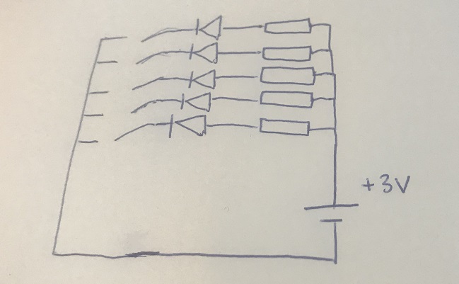
I use 50 ohms resistors based on that I have a 3 volt power source with 5x 2v(ish) LEDs connected to it.
I built the joystick tester through the following steps:
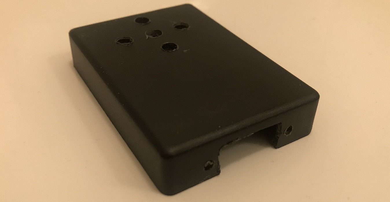
- Drill suitable holes in the box (för LEDs + db9-connector)
The result from this step had probably become more estethically pleasing if I would have had a real Dremel tool, and not a cheap, Chinese copy 😉
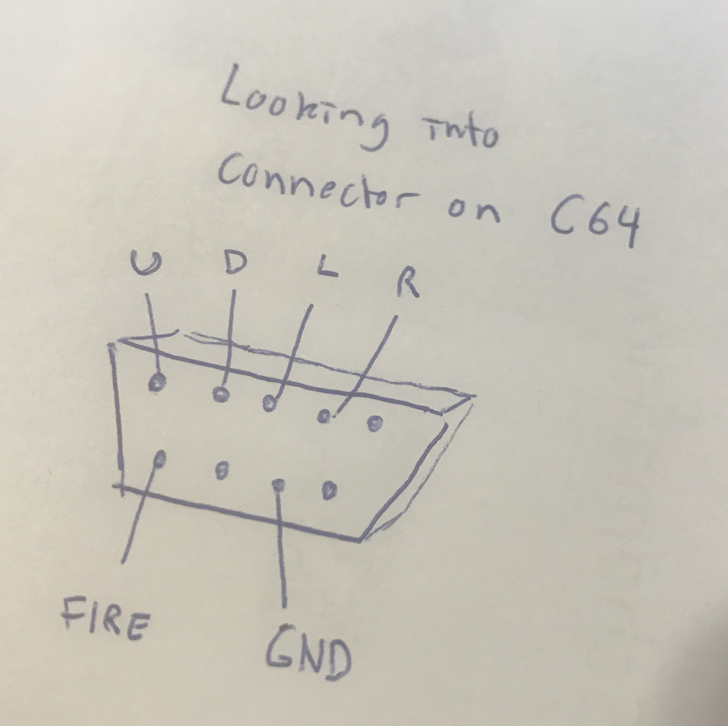
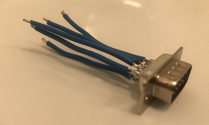
2. Solder cables to the db9-connector
Below is the layout for a joystick with 4 direction and 1 fire button. When you press the button or move the handle in any direction, the diod will be connected between + and ground. I am by no means an expert on electronics, so feel free to comment on my diagram below!
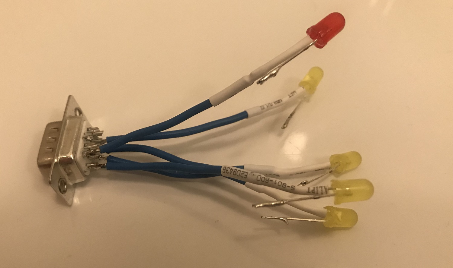
3. Connect the LEDs to the db9-connector
I am very fond of using shrink tubes for these kind of works.
4. Connect the resistors to a cable that will be connected to the +plus side of the battery holder.
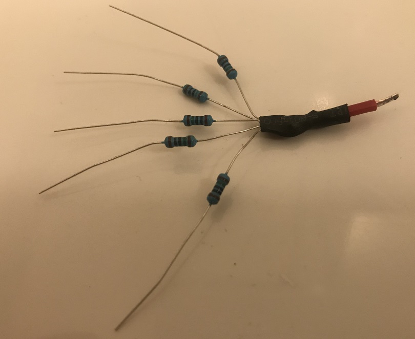
5. Solder the resistors to the LEDs. Solder the (red) cable to the +plus on the battery holder, and solder one cable from ground to the db9-connector.
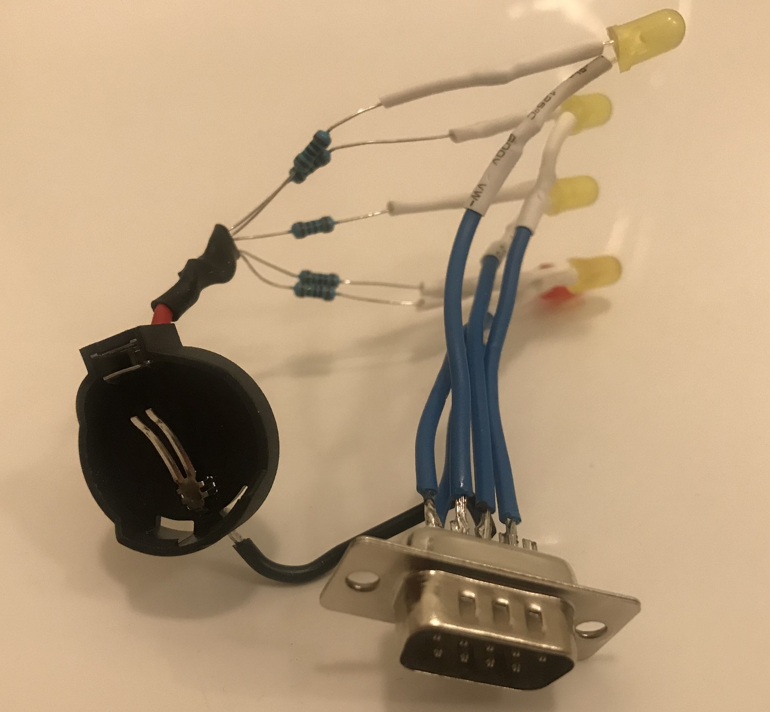
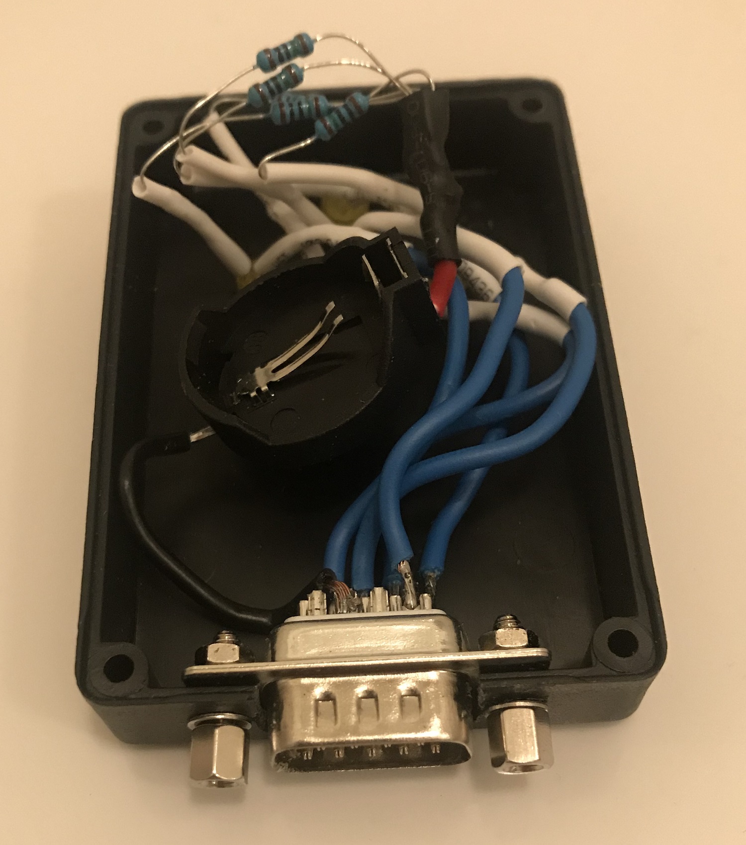
6. Stow everything into the box!
First I planned to use some holders for the LEDs, or some sort of glue. However, the box is rather compact, so they are held in place anyway.
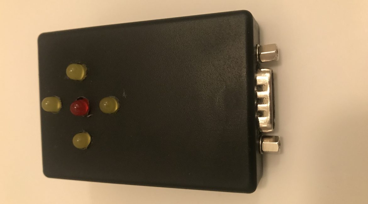
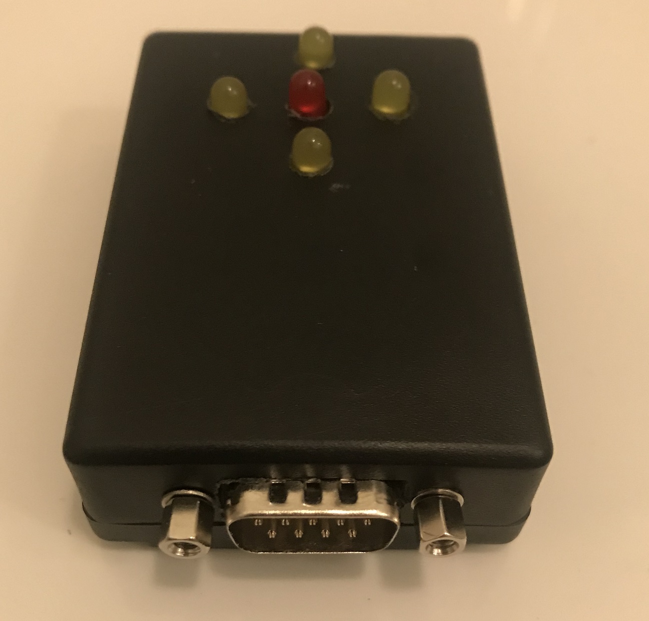
7. Done! Try it by connecting a joystick! See video at the end of this post.
A succesful project overall, even if the drilling and cutting of the box could have been done a little more smoothly. Keep an eye out for additional posts where I repair the joysticks!
whats te resistors value?
50 ohm.
Made a quick 3d printable case for this project. Don’t have the components right now so have not tried the fit yet, but should be possible to cram it all in there I hope. Thanks for the inspiration.
https://www.thingiverse.com/thing:4743234
Hi! That box looks great! I will certainly 3D-print your design on my Ender 3 Pro if I make another joystick tester!