A guitar pickup is essentially similar to a dynamic microphone coil. For decades, dynamic microphones have been wired with the voice coil attached to the primary of the microphone’s transformer, and not referenced to ground (‘floating’). The microphone’s case is typically connected to the cable shield, which is connected to the microphone amplifier’s ground (see Rane’s website for more discussion).
By and large, dynamic microphones are very quiet devices as a result of the combination of transformer isolation and balanced, floating transmission lines throughout, as well as shielded, humbucking coils.
So why not guitars? Guitars are notoriously plagued by noise. Humbucking pickups are only a partial (though important!) solution. The obvious solution is to float the guitar pickup to a balanced output, just like a microphone. A similar idea was published this 2001 patent application by John Elliot Petherick:
Petherick’s Patent Application
While a good start, the circuit is more complex than necessary. First, it uses two independent coils. That means either two single coil pickups used together or a humbucker with a coil tap. Coil taps are common in aftermarket pickups, but less so in OEM pickups, and it just isn’t practical for most people to rip out a perfectly good stock pickup.
The purpose of the coil tap in Petherick’s circuit is to provide a ground reference for a differential circuit. But the ground reference isn’t necessary, in fact it requires the addition of two other parts: a dual potentiometer for the tone control (with a second tone capacitor), and a double-pole, double-throw (DPDT) switch for each pickup to change between balanced and unbalanced output mode. Not only does that mean another part or two, it also means drilling holes in your guitar to add the controls, with the associated risk of accidentally whacking the switch while you are jamming away!
Fortunately, it isn’t necessary to use two coils (humbucker with a coil tap, etc.) and ground reference everything. It thus also isn’t necessary to use the DPDT switch to go between balanced and unbalanced output. Simply float the pickup, and when a TS plug is connected, the guitar’s TRS jack will ground reference one side with no user input required. The same TRS jack will work balanced or unbalanced, depending on the cable that is connected. Backwards compatibility is maintained!

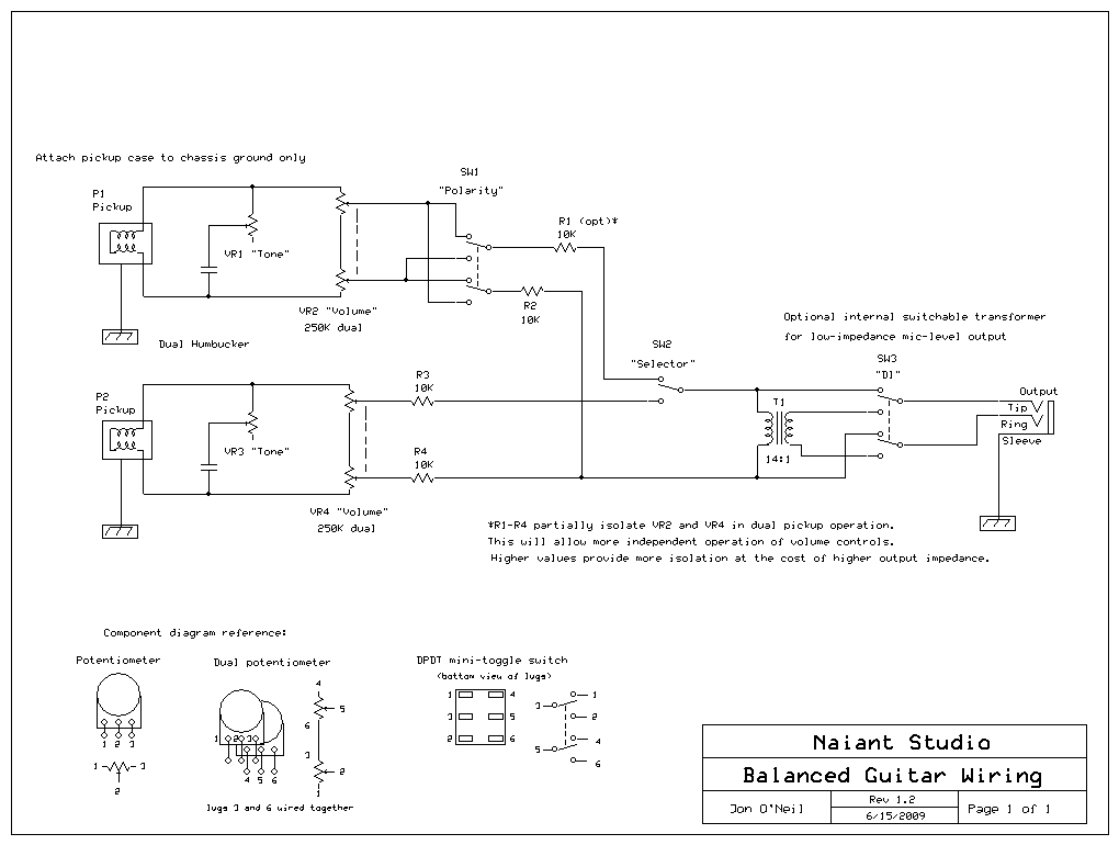
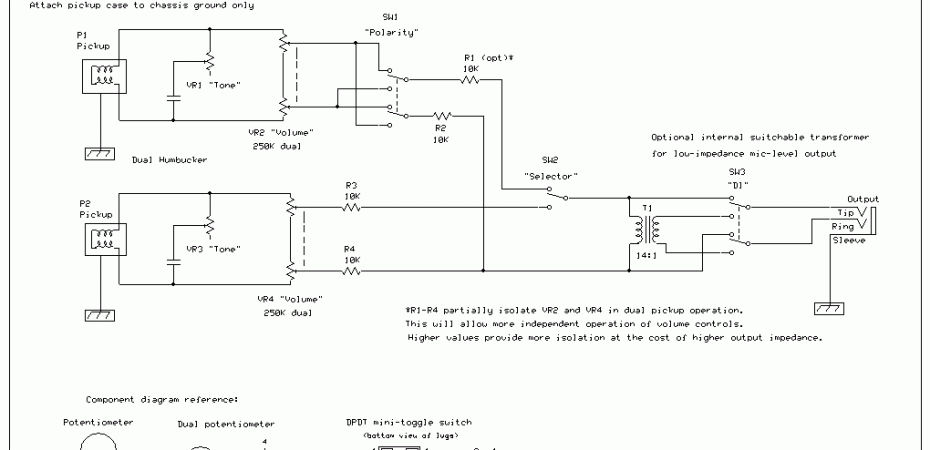
The schematic above shows typical balanced wiring for a dual humbucker guitar. The tone pots are single, and the volume pots are dual. The value of the tone pot is standard, but the value of the dual volume pot should be half the standard value—that is because both sides of the pot are a series load on the pickup, so a 250K dual pot as shown provides the same load as a 500K single pot would in an unbalanced configuration.
Note the addition of the 10K resistors to isolate the volume controls from each other. This is a partial solution to the well-known “master volume” problem when using the middle pickup position (both pickups in parallel). The solution used for unbalanced guitars (wiring the wiper to the pickup) isn’t my favorite as it reduces volume by loading the pickup, which changes the pickup’s tone and provides a less linear gain change. Instead, these summing resistors help isolate the two volume controls from each other. It’s not a perfect solution, but it helps. Larger values would work better, but the output impedance would increase, which is generally a bad thing.
However, note the addition of an onboard transformer. I show this as switchable, such that you can select normal or mic-level output. Using the mic-level output, you can make a fully balanced connection to any standard microphone amplifier.
Another option is a 4:1 transformer hardwired to the output jack—that would reduce output impedance by a factor of 16. The lowered output impedance solves the problem that guitar cable capacitance causes (and would allow the use of larger summing resistors, providing better isolation between the pickups’ volume pots). The cost is a bit of signal level (about -12dB), but it’s generally not a problem for an amp to generate extra gain.
Also note that I have shown a typical polarity inversion switch on one pickup, and I’ve included a rather badly drawn reference diagram to assist the schematically challenged!
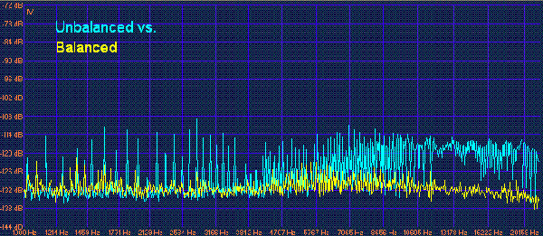
Either Petherick’s circuit or this floating design does require dual pots for volume, so those components are a few more dollars. But the benefits are tremendous! See the attached graph of a noise comparison between unbalanced and balanced connection, the same guitar wired for balanced output, and measured with both unbalanced and balanced interconnection—this is a “no hands” signal—no body parts touching the bridge or strings at all, no strings resonating, just the background hum and noise:

While it’s simple enough to rewire a guitar for balanced output, the difficulty lies in the input stage of the guitar amplifier. Since guitars have been unbalanced for over 50 years, so have amplifiers. Balancing the input stage of a tube amp would best be accomplished with a transformer. Solid-state amps can easily be designed with a differential input opamp stage, but an existing amp would be difficult to modify.
Placing a transformer in an external chassis in front of the amp’s input is an acceptable solution to eliminate transmission line noise and gain the benefit of the floating pickup design. Another alternative is to always use the transformer-balanced output of the guitar and connect the guitar to a microphone amplifier, with the output of the microphone amplifier feeding the guitar amplifier. The microphone amplifier could also makeup the level drop from the step-down transformer.
Of course, an active circuit inside the guitar could provide these as well as many other benefits (such as full isolation of all controls), but not everyone wants a battery in their instrument. A fully passive solution will always have some trade-off, but I feel the above circuit is the best possible compromise and a significant improvement on the status quo.


I love this idea and design, cutting out so much of the background hiss seems like it would be a top priority for more studio musicians though I’ve never seen anything like this in practice. How would this be adapted to an instrument with one volume and one tone pot?
A single tone and volume pot can be wired after the pickup selector switch, otherwise as shown in the schematic.