Dynaco SCA-35 Project

SwiftEnthusiast

Site Supporter
Site Supporter
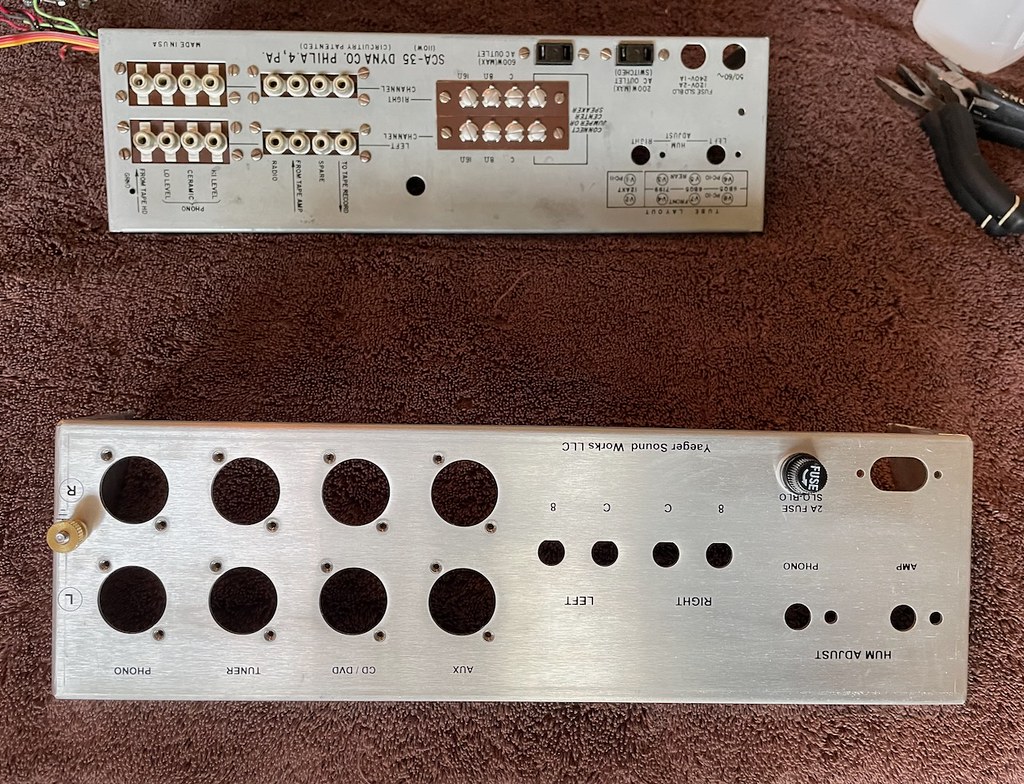
I have a Dynaco SCA-35 that I bought in working order about three years ago. I enjoyed listening to it for a couple years or so until one day it suddenly developed a moderate hum (same level in both channels, did not change with volume). Swapping in a spare set of used tubes didn't make any perceptible difference, so I put it aside until I had time to investigate further... which turned out to be this weekend.


53244805355_d59398a221_b.jpg

This is the patient.

53244313831_d365b374a3_b.jpg


53244604893_525c86035b_b.jpg


53243419492_abb235bae5_b.jpg

I checked the power supply capacitors first and it turned out there were problems there. Both sections of the smaller 50 uF / 50 uF capacitor were no longer capacitors (open circuits). The capacitance measurements looked good for the larger capacitor, but the meter reading for some sections would drop out with slight changes in force/direction of applied meter probes. Seemed like a marginal internal connection. There was also what appeared to be a little bit of corrosion at and around the base of some terminals. Looks like it is time for new power supply capacitors.

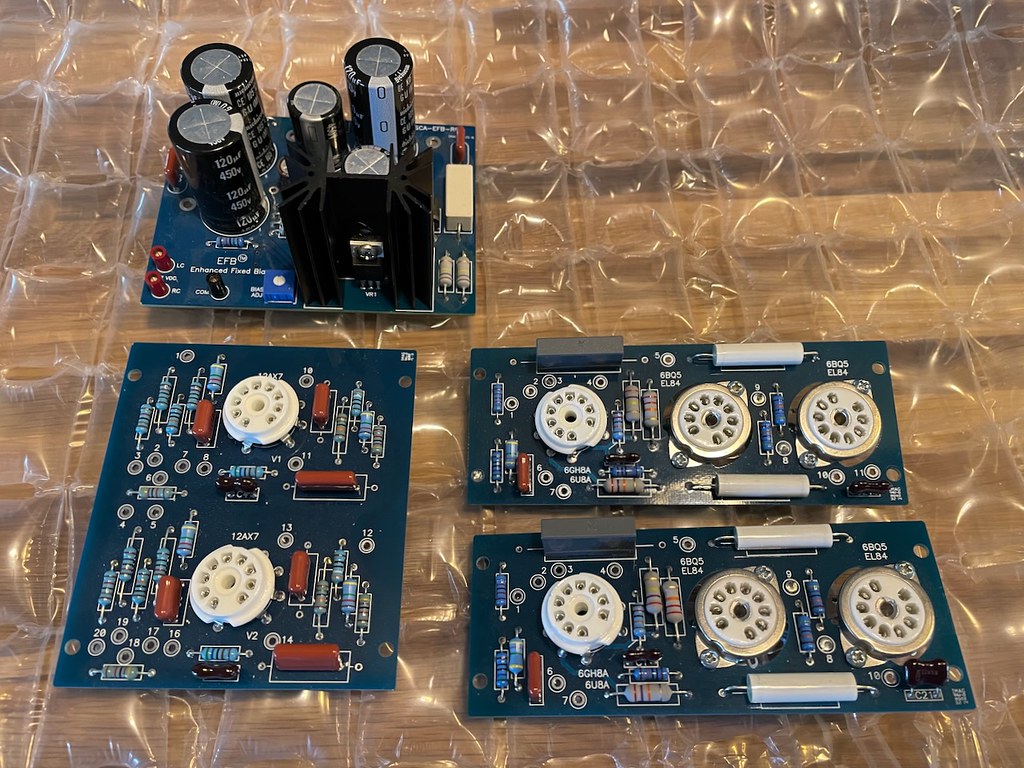
I decided to resolve this with one of the available power supply board upgrades. I was thinking about working towards a full set of Dave Gillespie EFB boards over time - power supply board now and then upgrade the other boards when mine needed attention. Then I came across an auction listing for a full set of these boards already assembled after the seller's plans changed. Seemed like it was meant to be - so I bid on them and won the auction today.

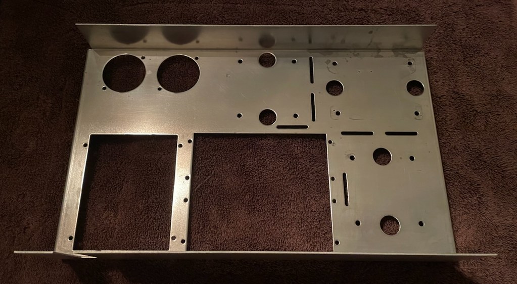
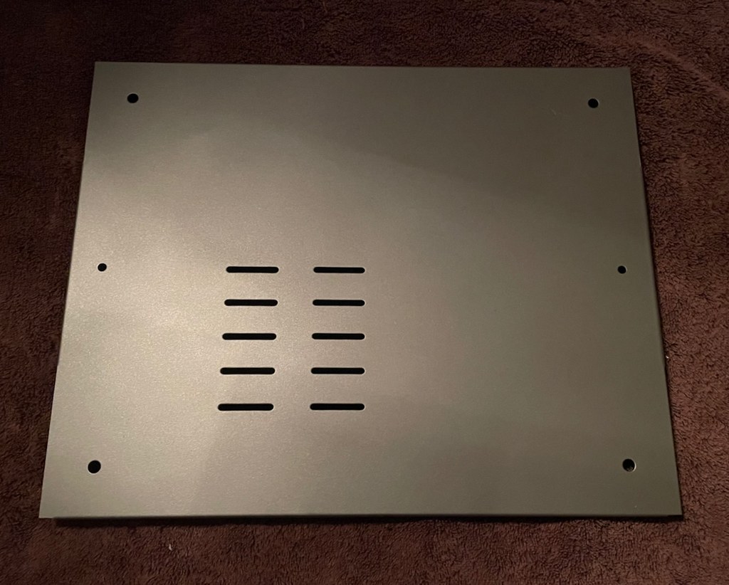
So this has developed into a project. It won’t be a full restoration or anything close. I just plan take it a little further apart, clean it up internally, upgrade to the new Dave Gillespie boards, implement some other minor updates, and then put it back tougher. I’ll share updates here as it progresses.
 
Last edited:
DaveG's boards are first rate quality. My SCA-35 sounds very nice with the new boards.
That is good to hear. I've read good things about this upgrade, but have so far only heard the SCA-35 in stock form. Looking forward to some listening after the upgrade.
 
With Dave's assistance, I used the SCA power supply board in my ST-35 build - because I wanted the extra room of the chassis over the pretty compact ST box. It's hard to say sufficient good things about the results from Dave's boards and his willingness to help. Since you have them in hand, going all in with the set would be a wonderful overhaul.
 
53256577098_0c38e41301_b.jpg

The assembled Dave Gillespie boards arrived in the mail yesterday. These are nice boards. They had been sitting around for about a year and have gathered a little dust. Aside from that, everything looks great on initial inspection (condition, assembly, solder work, etc). I’ll inspect more thoroughly and double check everything soon.

Earlier in the week, I completed an initial assessment of the additional parts that will be needed and got them on order.

The amp has been disassembled...
53256637509_f3d17d739a_b.jpg


53256287256_098211abe8_b.jpg


53256637524_352baf8809_b.jpg


53256637469_c422282b1d_b.jpg


53256774125_d601dbac3c_b.jpg


Cleaning things a bit up now, hopefully will finish that tomorrow.
 
That's in very nice condition, especially the faceplate. Wish I had bought one of these (or a ST-35) before prices went through the roof. I used to perform Dynaco warranty service back in the day, and still believe these are one of the best sounding amps ever made. Good luck with the project!

Jack
 
That's in very nice condition, especially the faceplate. Wish I had bought one of these (or a ST-35) before prices went through the roof. I used to perform Dynaco warranty service back in the day, and still believe these are one of the best sounding amps ever made. Good luck with the project!

Jack
Thank you! I was happy to find one in this condition and had been enjoying it up until the hum problem developed. It is cleaning up fairly well so far, aside from the bottom panel (which I may end up painting).
 
I made a little further progress on this project. But first, I wanted to share a wealth of information I came across in the form of a thread started by Dave Gillespie over on AudioKarma:

Hidden Treasure: Bringing Out The Very Best of Dynaco's SCA-35

If you have not already read that thread and have any interest in the SCA-35, I highly recommend at least reading the first post. There is some really great information there. I have increased the scope of this project to include some of those improvements. I will elaborate more as I get to those parts of the project.


Back to my project...

I am pretty happy with how things cleaned up. The top cover, the outer front panel, and the transformer finish were all in pretty good condition, with just minor things here and there. Cleaned them all up with a damp cloth.

53270313419_dde10e6c33_b.jpg


53270422550_c7b6349f78_b.jpg


The other metal work got a little more attention. Although it all had most of the original plating intact, they had spots and/or areas where the plating was gone and the underlying metal was rusting.

53264472728_bbb965e0e1_b.jpg

For example, here is the inner front panel. The inside was in great shape, but the bottom and outside had some developing corrosion.

53264530554_43e006fb8b_b.jpg

After cleaning up these parts, I used Rustoleum zinc rich spray paint (bright galvanizing) to spray or spot brush those areas. That paint does not stand up well to anything much beyond careful handling, so something I would only consider for areas that won’t be exposed to regular handling and contact once this is reassembled. But I like it for this type of usage - a sacrificial coating that should help hold off corrosion for a long time, and which can be easily removed later (wipes off with alcohol) if someones wants to apply something better, refinish those parts, etc.

53264472648_49099b9443_b.jpg

The plating was in worse shape on the bottom cover so I decided to paint it. Cleaned it, wet sanded it, and then painted it with a silver lacquer spray paint by Glidden. The finish on the other side looks about the same. I masked off the side ears to maintain the original electrical connectivity between all the chassis metalwork (I am planning to earth ground the chassis for safety, otherwise I think painting the ears as well might actually help reduce magnetically induced hum per the 'Eliminating Amplifier Hum -- Part 2' section of Dave Gillespie's thread I linked earlier in this post).

53264530519_3f21d490cc_b.jpg

Assembly begins. I am using a ST-35 hardware kit from Dynakit Parts for internal assembly.

That's it for now.
 
Last edited:
A package arrived today that I had been eagerly awaiting...

53275639834_78c9ca37ee_b.jpg

Among other things, it contained this beautiful new rear panel for my SCA-35! Don’t be fooled by the image perspective, the new and original panels are the same size.

This is part of the project scope increase that occurred after I came across that SCA-35 thread on AK (linked in my previous post). If you have checked out that thread and got far enough through it, you probably saw the posts by AK forum member BuzzK regarding the design and production of this rear panel (and then later in the thread, a relay based input selector board). He has done a number of other projects like this over there. I plan to go back and explore them further after I get this project completed. Seems clear to me he shares these projects to help out fellow audio enthusiasts and I really appreciate that.

Prior to finding that thread, the plan I had settled on was to maintain the original input configuration and reuse the original rear panel with most of its original components (including input connectors). The only exceptions would be a new grounded power cord and Dynakit Parts replacements for the speaker terminal strip (mine was rusting through in places) and the fuse holder (mine was cracked and fell apart when I tried to remove it). The image above shows it reassembled with the new terminal strip and all the other original parts. I went ahead and reassembled it to that point just so I could store all that together.

When originally deciding the scope of this project, I had considered simplifying the inputs. Dropping at least the tape head input would simplify the low level input path (phono only). And I could opt to increase the spacing between input connectors with the Dynakit Parts input connector board upgrade (or a simple insert of my own design). That would accommodate a wider range of modern cables while also eliminating the connection of the outer conductor to the chassis at the input jacks (to allow some flexibility in those details).

I was still on the fence after considering it for awhile, so I just decided to save that as a potential project for another day. And then I found that other thread which got me thinking about it again. And then I got far enough through the thread to see and read about that redesigned rear panel. I contacted BuzzK shortly after that to see if by chance he still had any of those panels and was willing to part with one. He had two and was willing to sell me one for a very reasonable price. I promptly claimed that one, along with the power connector, fuse holder, and fuse. I also ended up ordering one of his relay input boards. I did contemplate including that in this current phase of my project, but decided to save it for later. If my selector switch ever fails and/or I want remote control, I will revisit the input board idea then. Note that this relay board differs from some commonly available boards I have seen (eBay kits, etc) in that it shorts the unused inputs like the original Dynaco selector switch.
 
Last edited:
Completed the front panel wiring this evening, although I have not tested it yet...

53286265571_8be5de3b42_k.jpg

Since I was going to be making a number of changes, I decided to just rewire it. First step was to remove as much of the existing wiring as I dared. I decided not to push my luck with the PECs - I left them in place and carefully worked around them.

53286730705_5a86eaf796_k.jpg

Rewired. The dangling cloth wires will connect to the source selector switch. The dangling shielded wires will connect to the amplifier boards.

All the pots are original and retain their original functions. All the switch functions have changed to some degree - I decided to replace them all since they are available, low cost, simplify this task, and simplify reverting back to original if I ever decide to do so.

Revised switch functions:
  1. Stereo/Mono -> Mute
  2. Loudness -> Loudness, but with Dave Gillespie’s modified design
  3. Filter -> Tone Control Bypass
  4. Power -> Tone Control Bypass Gain (+10 dB or +17 dB, relative to no TC bypass)
I plan to relocate the power switch to the rear panel (more details on that later). So, I had a fourth switch without a purpose. I was considering having it switch between two different attenuation networks (to reduce the much higher gain that results from bypassing the tone controls). For example, I considered having it switch between the 0 dB and 12 dB networks described in Dave Gillespie's thread. Or 6 dB and 12 dB. The switch also serves as a convenient place to mount those networks. But I didn't have the right capacitor values on hand for any of that, without paralleling multiple capacitors, etc. I have some assorted values on order, but it will be some time before they arrive. I did have the correct values for about 10 dB though, so I just went with that for now. The other switch position is just the full gain without any attenuation. I don't anticipate I will have much use for that. Once I have some experience with the 10 dB setting and the correct capacitor values on hand for the other attenuation levels, I may come back and revisit this. I think it should be straight forward to revise this to switch between two different attenuation networks.
 
Last edited:
Hey Swift, you've got me looking at SCA 35's today...

I am reading the AK link and Dave's other documentation as I go, but do you mind if I ask a few questions here too?

Few years ago, I modified a ST70 to run the tubes4hifi driver board. I was very happy with the contemporary adjustments made in that circuit.

I understand that the bias adjustment is a major attraction here for the SCA 35. But I have run a clean PAS 2 preamp and unfortunately I do not have fond memories of it. Subjectively, how does this power stage sound? Is this a good candidate for a preamp bypass switch with a nice blue alps pot for a simple "integrated"?
 
There is a tone controls bypass documented by Dave G. at AK. See post 17.
John
 
There is a tone controls bypass documented by Dave G. at AK. See post 17.
Thank you for the reference to the relevant post # in that thread.

I understand that the bias adjustment is a major attraction here for the SCA 35. But I have run a clean PAS 2 preamp and unfortunately I do not have fond memories of it. Subjectively, how does this power stage sound? Is this a good candidate for a preamp bypass switch with a nice blue alps pot for a simple "integrated"?
I don’t have any experience listening to the SCA-35 without the tone controls yet, but I am looking forward to gaining some once I complete this project.

I am still learning as I go myself, but here are my thoughts. First, if I understood correctly, the simple integrated configuration you are considering would be: source selector switch -> volume attenuator -> SCA-35 power amplifier boards (preamp, tone controls, and possibly other preamp features bypassed or removed)? In any case, if it entails bypassing the tone controls, I anticipate that the gain will be much higher than needed for typical high level sources. And so the effective range of the volume knob will be significantly reduced and its sensitivity significantly increased. Adding in some attenuation should improve that situation, along the lines of the RC attenuation network described in Dave Gillespie's thread (Post #17 per Nerdorama's response above). Note that if the balance control is removed, without replacing it with equivalent resistors, that will change the RC values required to achieve a given level of attenuation.

If there is no desire to have tone controls at all though, reducing the gain of the amplifier could potentially provide better results. If I were considering such a project, I think I would start by investigating the possibility of swapping in ST-35 amplifier boards as they are already designed for an appropriate level of gain without the tone controls. I have seen references to the idea here and there online, but have not seen any documentation, projects, or even photos of such a thing. But then again, I haven’t specifically looked for that either (what little I have seen is what I came across in the course of my project). If it is possible without too much trouble, seems like that would be a great way to go for a Dynaco based simple integrated amplifier.
 
Thank you for the reference to the relevant post # in that thread.


I don’t have any experience listening to the SCA-35 without the tone controls yet, but I am looking forward to gaining some once I complete this project.

I am still learning as I go myself, but here are my thoughts. First, if I understood correctly, the simple integrated configuration you are considering would be: source selector switch -> volume attenuator -> SCA-35 power amplifier boards (preamp, tone controls, and possibly other preamp features bypassed or removed)? In any case, if it entails bypassing the tone controls, I anticipate that the gain will be much higher than needed for typical high level sources. And so the effective range of the volume knob will be significantly reduced and its sensitivity significantly increased. Adding in some attenuation should improve that situation, along the lines of the RC attenuation network described in Dave Gillespie's thread (Post #17 per Nerdorama's response above). Note that if the balance control is removed, without replacing it with equivalent resistors, that will change the RC values required to achieve a given level of attenuation.

If there is no desire to have tone controls at all though, reducing the gain of the amplifier could potentially provide better results. If I were considering such a project, I think I would start by investigating the possibility of swapping in ST-35 amplifier boards as they are already designed for an appropriate level of gain without the tone controls. I have seen references to the idea here and there online, but have not seen any documentation, projects, or even photos of such a thing. But then again, I haven’t specifically looked for that either (what little I have seen is what I came across in the course of my project). If it is possible without too much trouble, seems like that would be a great way to go for a Dynaco based simple integrated amplifier.
Interesting. I have a few messages out on eBay, maybe this will become a project for me.

More gain within the amp could be a good excuse to mess with transformer-based I/V stages in my dac. Maybe I could build an input that uses V1 as a reconstruction filter / low pass coming out of an R2R dac.

Would have to modify the selector switch, but this is kinda what Fender modifiers do - build different preamps into the silverface normal channels
 
I've had one experience with a transformer coupled DAC output. It was a cheap Behringer digital EQ that had pretty lousy analog circuits. Connecting a transformer directly to the DAC chip output pins was a tremendous upgrade. It became much more dynamic and micro detailed and was still smooth as silk.
 
I've had one experience with a transformer coupled DAC output. It was a cheap Behringer digital EQ that had pretty lousy analog circuits. Connecting a transformer directly to the DAC chip output pins was a tremendous upgrade. It became much more dynamic and micro detailed and was still smooth as silk.
Very cool. I spent some time last year building op amp IV and reconstruction stages. Would be fun to run those as is to a class A mosfet, and have the option to run a completely different downstream into a transformer and EL84s in PP
 
Been planning an sca35 rebuild for awhile now. I have run it without the tone controls a couple ways, it sounds good. Mine developed a bad oscillation, so I need to do the work sooner.

Bought the Gillespie power supply board and the st35 power amp boards which he said would fit. Planning on keeping the phono stage, but just using an eBay stepped attenuator for volume right before the power amp.
Oh interesting. I am considering doing something similar - I most definitely will be permanently disabling the tone controls, and if I understand correctly, the largest distinction between the SCA 35 PC10 boards VS the ST 35 PC13 boards is the gain of the driver tube.

Phillip, are you subbing the phono stage to the PAS circuit, or keeping the original with the old IC?

EDIT:
the PC10 board only needs 0.18 Vac to run at full power due to the pentode driver.
PC13 is looking for 1.0 Vac.
Look here to confirm

Coming from the first watt group, these numbers appear staggeringly low. I wonder what kind of DAC IV I could mate with these amps.
 
Last edited:
Back
Top