


Micro Sumo Robot
Here is the Micro-Sumo bot that I designed and built. I finished my Mini-Sumo and started looking at the next smaller size. A robot 50mm square looked like something I could make so I decided to give it a try. The design was made in SolidWorks. All parts were made by me. It weighed in at 107 grams. A bit heavy but I can trim that much in a couple places.
As the Video shows I have some work to do on the code. The bot is so fast it spins out of the ring. I hope to have this corrected soon and will upload a new video when it is complete.
Updated 8/1/2010
Here is the latest video. With some programming help from Patrick again the insane speed has been tamed down and the bot now stays within the ring.
Here is how I made it.
Chassis:
Chassis plates are made from G10 phenolic 1.5mm thick. Bot dims are 49mm x 49mm x 55mm tall. Lower plate supports the motor/gearbox. The middle plate is used to mount the Edge Sensors and the Upper Plate supports the Battery holder and Sharp IR Sensor plus risers for the PCB.

Motor/Gearboxes:
Ordered these from GizmoZone #GH8102S-B, 10mm dia. x 20mm long. 26.5:1 planetary gear ratio. The gearbox detail that holds the geartrain is Delrin plastic.


Wheels/Tires:
These came from the slotcar world. They are standard 0.79" (20.0mm) in diameter and I cut them just wide enough to save the hub. Tires are natural closed cell foam rubber 0.25" (6.4mm) wide.
Gears:
These items are also from slotcars. 64 pitch 38 tooth spur and a 12 tooth pinion. 3.16:1 gear ratio. Axles are 0.094 dia. and each axle rides in (2) ball bearings.

Battery Holder:
I could not find a suitable battery holder for 4x 1/3AA rechargeable so I made my own. It is made from a piece of nylon. Copper plugs provide the terminals and a G10 keeper is on the other side. Held in place between the Sharp IR screws and a rubber band.


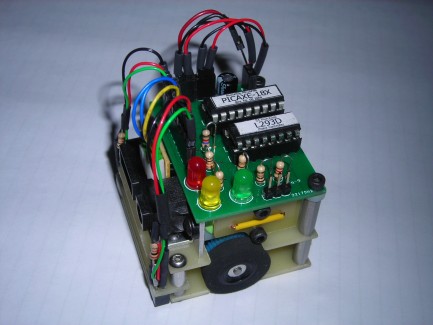
PCB:
This is my first attempt at designing my own board. It was done in Eagle with some help from Patrick McCabe. It uses the Picaxe 18x microprocessor with a L293D motor controller chip. 3-LED's provide the 5-second start sequence and female headers for all connections except for the programming cable.


It uses aggressive and angry behavior to push opponents or obstacles out of its ring
- Actuators / output devices: 2- Planetary motor/gearbox
- Control method: Full autonomous
- CPU: picaxe 18x
- Operating system: windows XP
- Power source: 4- 1/3AA NiMH @ 1.2 vdc rechargeables
- Programming language: Picaxe basic
- Sensors / input devices: 2-Fairchild #QRD1114 Edge Sensors, 1-Sharp #1GP2D120
- Target environment: Inside the 38.5cm Ring