How to Build Your Own XLR Cables: A Step by Step Guide - Studio DIY
/The XLR is one of the most commonly used cables in the pro audio industry, and as a result it's important to understand how they work. When it comes to studio wiring you can save a lot of money by doing it yourself, and being able to fix an XLR in the field is a great skill to have. Check out this handy guide for step-by-step instructions on how to build and repair your own XLR cables.
XLR Cable Basics
Modern 3-pin XLR cables are a form of balanced cable, which means that they have three conductors: positive, negative and ground. In most normal applications, pin 1 is ground, pin 2 is positive (as documented in the AES14-1992 standard, also commonly referred to as “pin 2 hot”), and pin 3 is negative. When attaching the connector to the cable, pin 2 and 3 will be connected to their respective positive/negative wires and the cable’s shielding will be connected to pin 1. There are a few exceptions to this rule, notably when it comes to certain pieces of vintage equipment, but that is beyond the scope of this article. For all intents and purposes modern 3-pin XLR cables are always wired “pin 2 hot”.
Recommendations and Notes
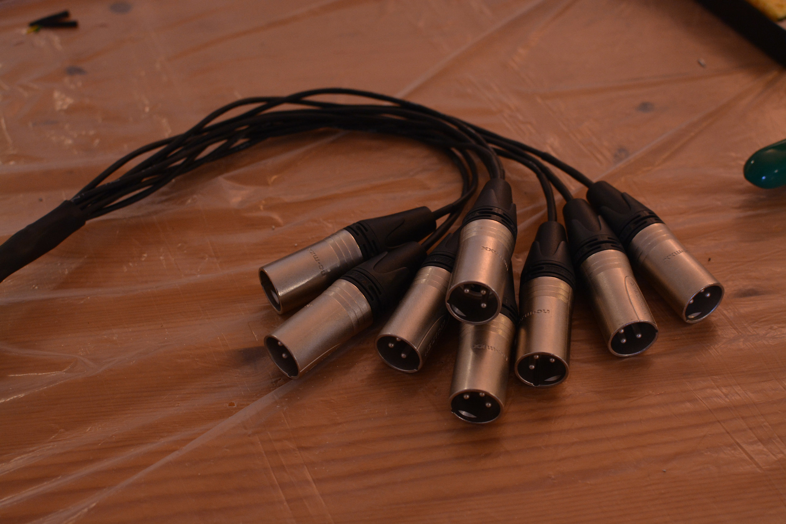
The finished XLr connectors as part of an 8-channel snake.
In my experience, building XLR cables is a great project for those learning to solder. I remember first doing this when I was about 16 years old and I’ve been doing it ever since whenever I’ve needed to build something custom or repair a broken cable. The components are all relatively large, which makes it easy for those still getting used to soldering and, in the event that you do make a mistake, replacing damaged connectors is inexpensive. However, I do recommend investing in a temperature-controlled soldering iron since it reduces the risk of accidently melting plastic components and ensures that you have enough heat to melt your solder. I also recommend using thinner gauges of solder (I use 0.031"/0.8mm) because I find it easier to work with and it melts faster. For a list of everything you need to get started, check out the links below.
Tools
Soldering Iron
Wire Strippers
Cable Cutters or Side Cutting Pliers
Needle Nose Pliers
Utility Knife
Third Hand Tool
Lighter
Materials
Cable (I recommend Mogami, Belden, or Canare)
Solder
Neutrik XLR connectors (models NC3MXX, NC3FXX (silver) or NC3MXX-BAG, NC3FXX-BAG (black))
Heat Shrink
Building the XLR Cables
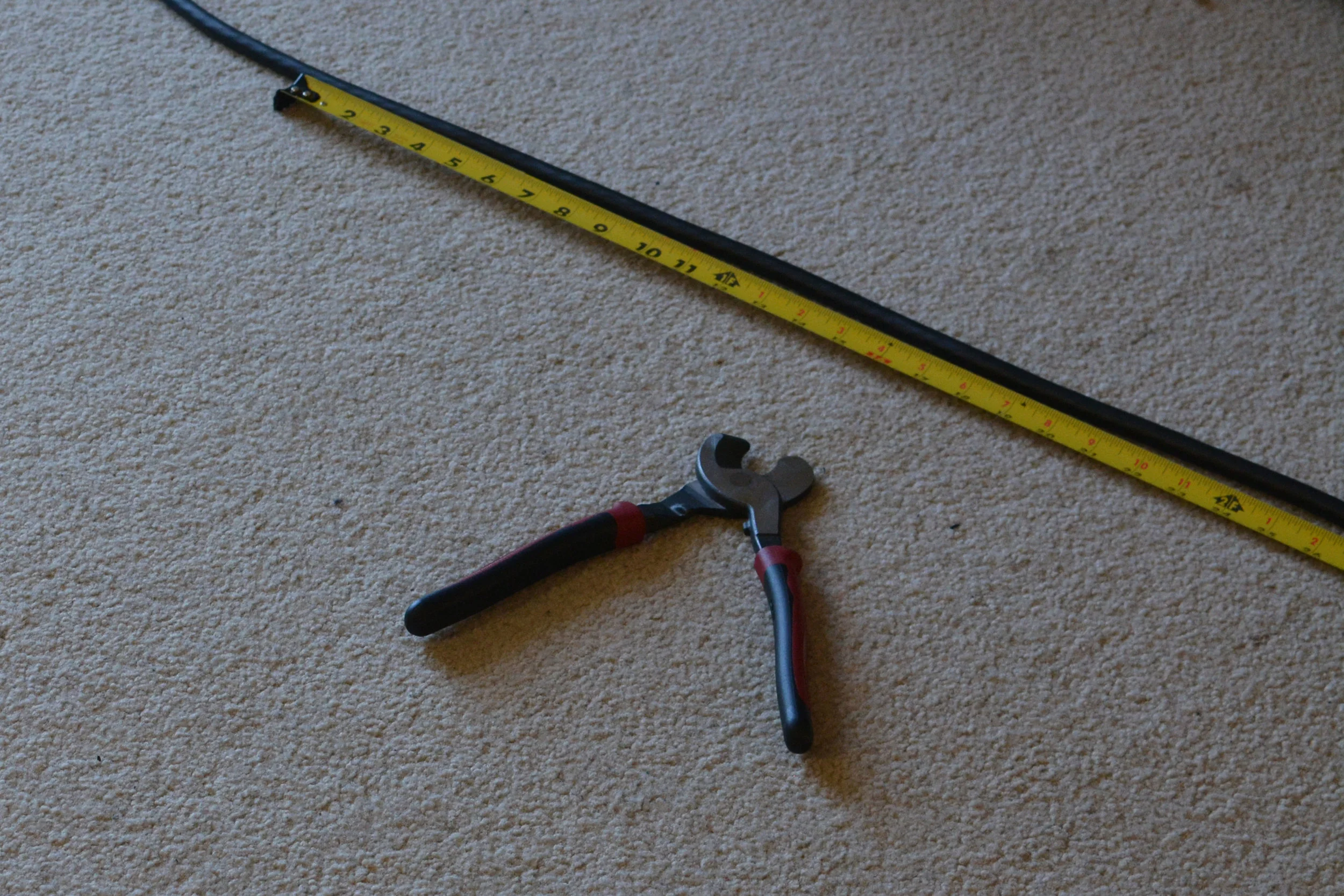
Step 1: Measure and Cut the Proper Length of Cable
First, measure the length of cable that you need and cut your cable down to the proper size. Most cable is sold by the foot, so if you’re making multiple cables you will need to cut them down to the proper length yourself. Remember to allow a couple of inches for each connector.

Step 2: Remove the Outer Sheath
Audio cable often has a thick outer sheath to protect it from the elements. Remove approximately an inch of the outer sheath at each end either using a wire stripper or a utility knife (depending on how thick the sheath is). Be careful not to damage the copper shielding and conductors inside the cable.

Step 3: Separate and Twist the Shield
Next, separate the copper shielding from the two conductors inside the cable and twist the individual strands of copper together. If your cable is built with a drain wire (a wire in contact with the shielding inside the cable to make grounding the cable on small connectors easier) I recommend intertwining it with the copper shielding. While one of either the drain wire or shielding can also be removed, this isn’t necessary as XLR cables have relatively large terminals. Some cables also have a cloth divider that needs to be removed at this stage. This can be done by separating it from the shielding and cutting it off with the utility knife.
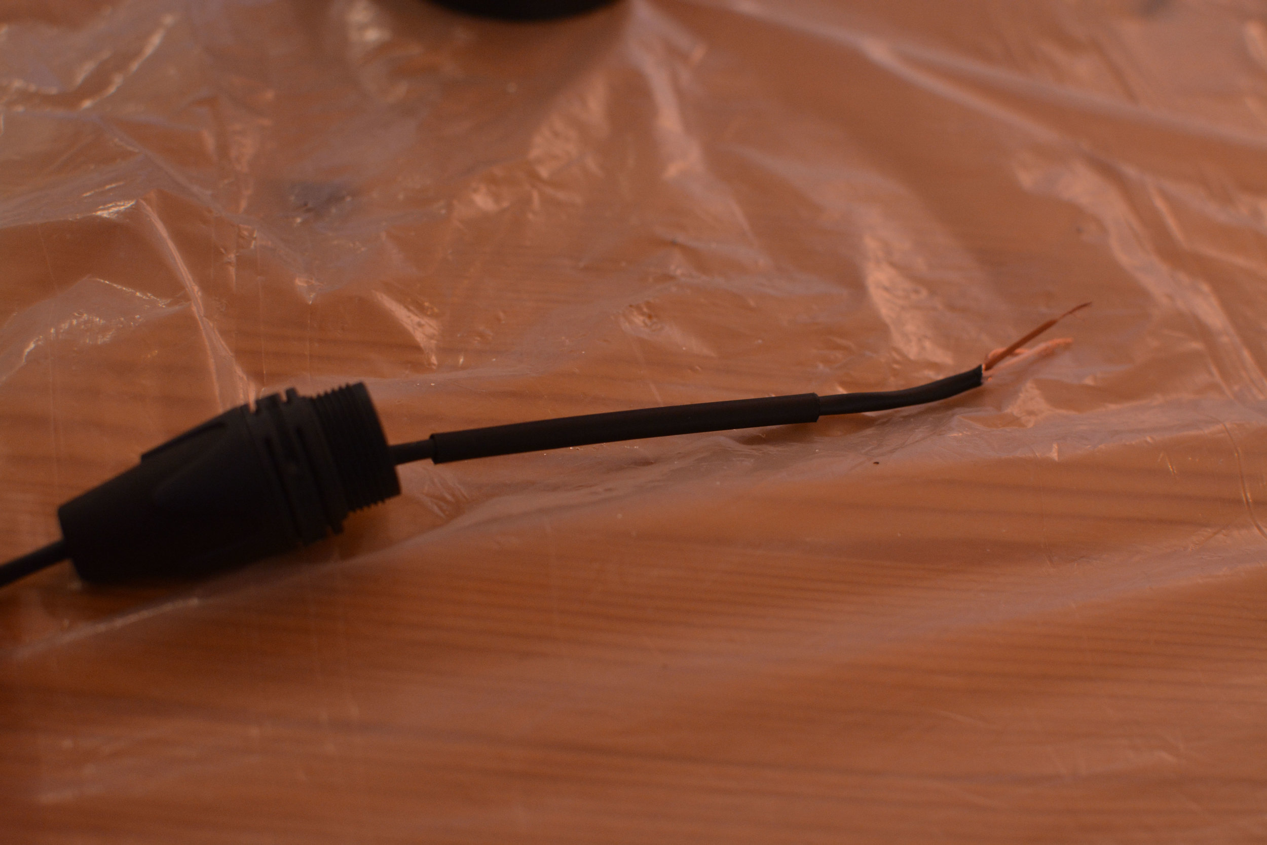
Step 4: Add Heat Shrink and Connector Boot
Measure and cut a length of heat shrink approximately 2-3” long and place it on the cable. This will help to cover any exposed connections and will provide some strain relief on thinner cables once the connector is attached. Place the boot of the Neutrik connector on the cable at this time. You can slide these down the cable to keep them out of your way as you continue working.
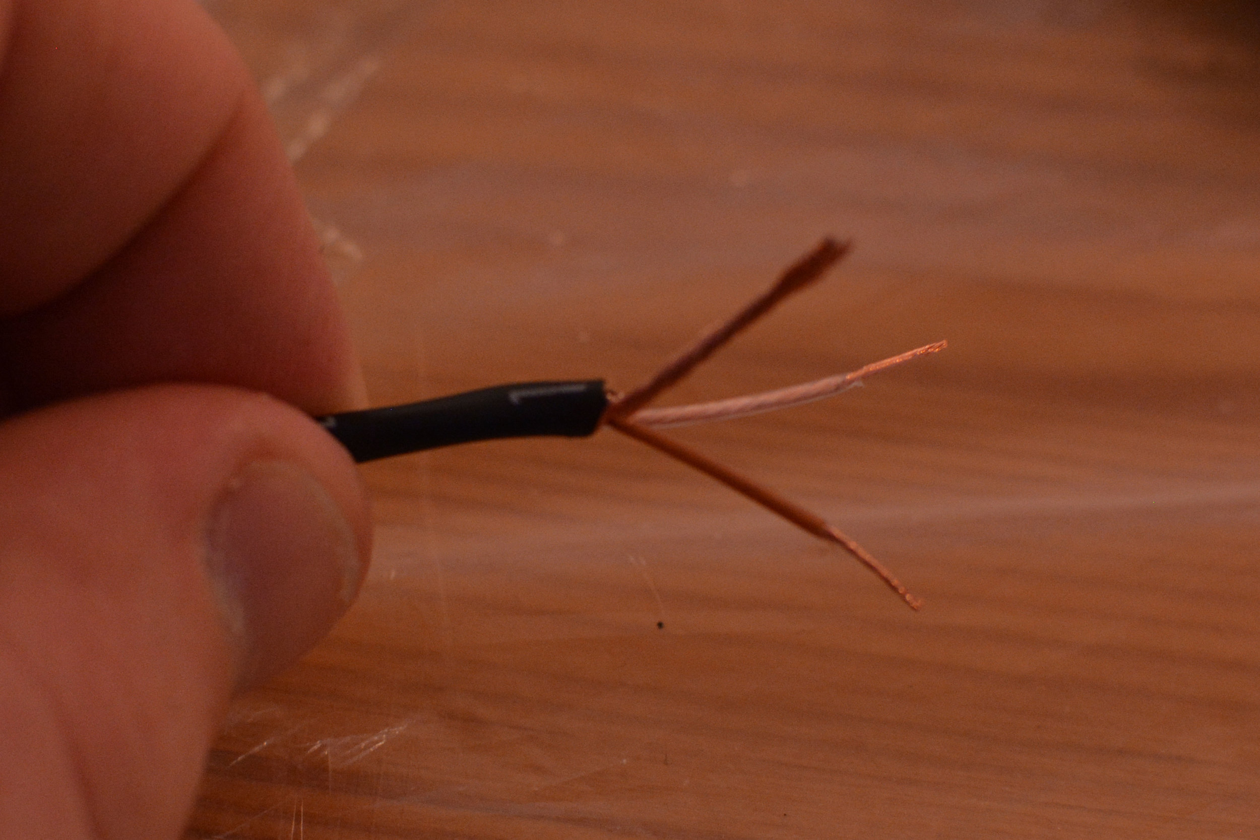
Step 5: Strip the Conductors
Use a wire stripper to strip both the positive and negative conductors of the cable. Only remove as much insulation as you need to solder the conductors to the terminals. Twist the copper strands together to prevent the wire from fraying. I’m using Mogami W2932 cable here (I took these photos as I was building a snake) so the coloured wire is positive and the clear is negative.

Step 6: Place the Wire in the Connector
Place the connector in your third hand tool and then place one of the wires in the proper cup terminal. You can gently hold the wire in the terminal with your soldering iron while reaching for the solder if necessary. I’m demonstrating here using the ground/shield, which I have covered in heat shrink. I like to place heat shrink around the shield to reduce the amount of exposed wire, but I’ve seen plenty of XLR cables built without doing this and most of them are fine. I have also placed heat shrink around the alligator clips on the third hand tool to prevent them from scratching or damaging the components I'm working with and generally recommend doing this.

Step 7: Solder the Wire to the Connector
Place the soldering iron on the joint and then feed the solder into the joint. You should use enough solder to fill the cup terminal, but not so much that it overflows. If necessary, hold the wire in place with a pair of needle-nose pliers while the solder cools. Repeat this step for the other two conductors, making sure to solder each wire to the proper terminal (see the diagram at the start of this article).

Step 8: Close the Heat Shrink
Once all of your conductors are soldered to their respective terminals, gently slide the heat shrink up the cable as far as it will go and then use the lighter to close it. Be careful not to burn the heat shrink or bend/break the conductors.

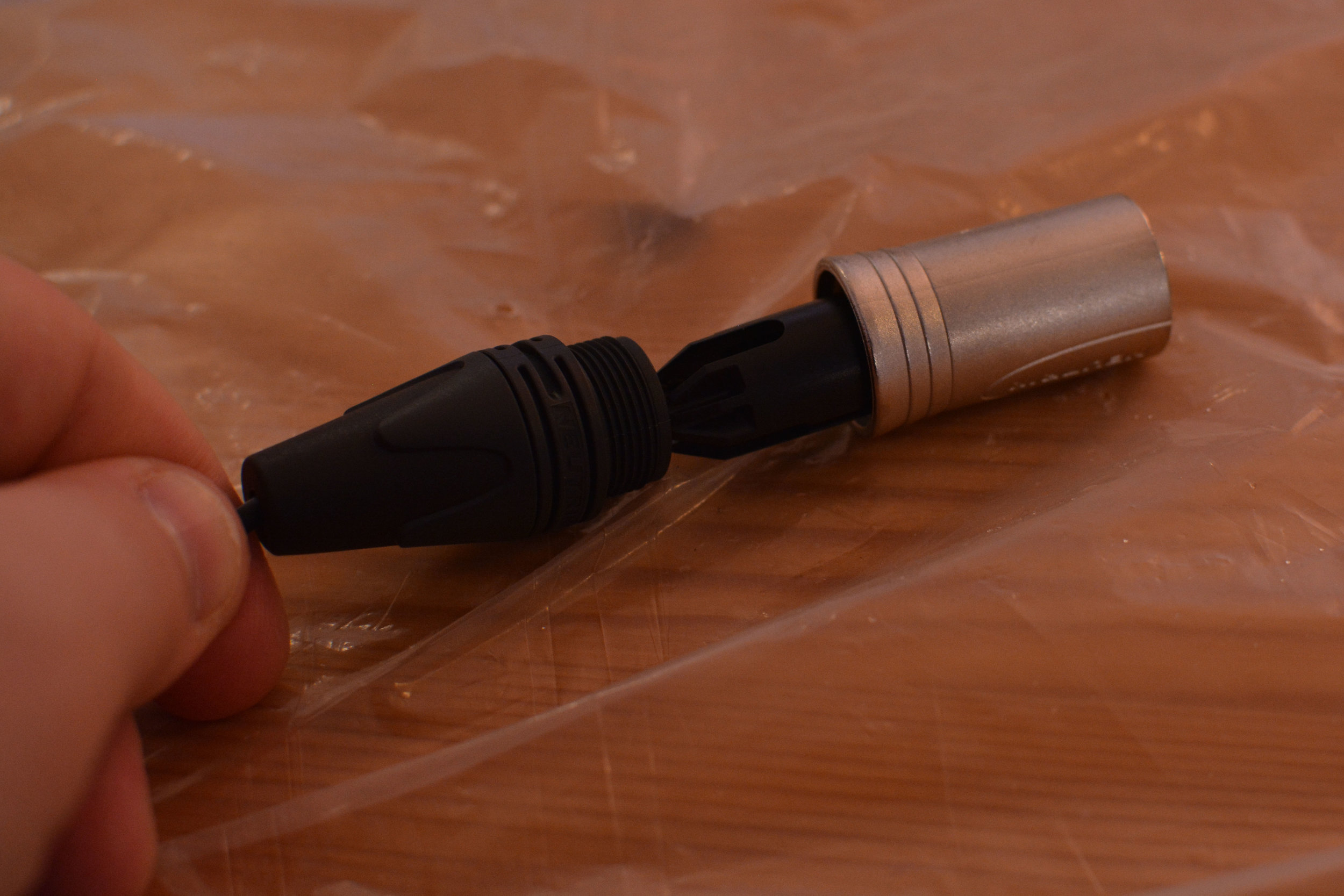
Step 9: Assemble the Connector
Place the black plastic sleeve around the cable using the slot in the top of the sleeve. Then place this into the grooves on the piece of plastic holding the XLR pins. Slide the metal casing over top of both of these components, making sure to properly align the groove in the metal casing with the tongue on the plastic sleeve.
Step 10: Tighten the Boot
Slide the boot of the connector up the cable and screw it into the threads on the metal casing of the connector. As you tighten the boot, it will force the end of the plastic sleeve inwards, which secures the cable in place and provides strain relief. You should hear a clicking sound as you tighten the boot of the connector.
If you're ready to get started, you can check out the links in the “Tools” and “Materials” sections above to order everything you need to build your own cables. Some of the materials for building cables can be tough to find (especially if you live in Canada) so for solder and replacement tips, etc. you can also check out digikey.ca, and your local music store may be able to special order cables and connectors for you.
The Home Studio Archive is reader-supported. When you buy from links on our website we may earn a small commission at no additional cost to you. We do not accept compensation for reviews and only recommend products we have used and tested ourselves.